Table of Contents
Advertisement
Quick Links
Quick Start Installation
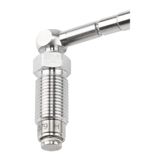
Melt pressure measuring chain with ø7,8 mm sensor and
½" 20 UNF thread
Type 4021B...
Contents
Front page: forming sensor bore
1.
General
2.
Important aspects of bore
3.
Forming bore
4.
4.1 Checking bore, thread and seal seat
4.2 Finishing bore
5.
6.
Back page: servicing, taring measurement/operating test,
Kistler factory calibration, servicing and repair
7.
8.
Taring measurement/operating test
9.
Kistler factory calibration
Foreword
Information in this document is subject to change without
notice. Kistler reserves the right to change or improve its
products and make changes in the content without obligati-
on to notify any person or organization of such changes or
improvements.
To the extent permitted by law Kistler does not accept any
liability if this Quick Start Installation guide is not followed or
products other than those listed under Accessories are used.
© 2012 ... 2020 Kistler Group. All rights reserved. Kistler
Group products are protected by various intellectual property
rights. For more details visit www.kistler.com.
1. General
• Diameter of sensor must not be machined
• Front and rim of sensor must be clean and free from
scoring
• Do not touch diaphragm on front of sensor with
sharp tool
• Only use recommended mounting tool
• Each sensor belongs to its unique charge amplifier.
Otherwise a measurement cannot be assured. Please
check: The sensor must have the same serial number
as the amplifier.
Requirements for structure material of the measuring bore
(Nozzle body)
Hardness
HRC
Tensile strength
Mpa
2. Important aspects of bore
Attention must be paid to the following aspects:
0,1 A
1
3
1. Ensure sensor centered
2. Seal seat
3. No centering bore
4. Do not mount sensor so it protrudes
3. Forming bore
7,8
0
-0,03
10,05±0,01
Form the bore with ½" thread and seal seat as shown on the
10,5
0
-0,03
following drawing.
4021B_002-597e-08.20
Then ream bore with Ø7,94 mm ream (Mat. No. 65007827).
0,1 A
max. R0.1
7,94
10,05
• Keep perpendicular and centered
4. Checking bore
Use the following tools to check and rework the measuring
bore:
4.1 Checking bore, thread and seal seat
The limit plug gage (Mat. No. 65000124) and fork wrench
11 (Mat. No. 65007836) are used together with Kistler grease
Type 1063 to check the bore and its perpendicularity.
• Always use Kistler grease Type 1063
4.2 Finishing bore
The Ø7,94 mm reamer (Mat. No. 65007827) can be used to
finish the bore.
Min.
Max.
40
55
1 200
1 820
2
4
A
1/2-20UNF-2B
+0,1
11,5
0
+0,05
0
A
+0,05
0
5. Mounting sensor
• Sensor bore and thread must be clean
• Seal must be positioned on the sensor
Apply copper paste, Molykote or high-temperature grease
sparingly to thread and sealing surface.
Screw sensor in at room temperature.
Tightening torque 40 N∙m.
• Use fork wrench 13 for HA & HS versions
• Use fork wrench 19 for H0, H1 and H2 versions
Heat empty (unpressurized) nozzle up to operating tempera-
ture (>150 °C) and retighten to torque of 40 N∙m.
• If the sensor leaks, tighten to maximum of 45 N∙m
6. Taring measurement/operating test
At operating temperature (>150°C) and with nozzle empty
(unpressurized), connect sensor to measuring chain and tare:
6.1 Taring by means of machine control system
Apply voltage to tare conductor.
6.2 Taring with PIN 3 and PIN 8
Short the two pins. Pin 8 must be live for this purpose!
M12x1 industrial connector, 8-pole male
#
Signal
1
Exct. GND
2
Signal GNG
3
Tare
4
Pressure signal 0 ... 10 V (at P1)
or 4 ... 20 mA (at P2)
5
Temp. signal 10 mV/K (at P1)
or 20 μA/K (at P2)
6
res.
7
res.
8
+Exct. (18 ... 30 V)
• If measurement noise arises when there is a large elec-
trical potential difference between nozzle and control
unit, the shield of the cable must not be connected to
the control box
Cable Type 1787A5
wire color
white
brown
green
yellow
grey
pink
blue
red
Advertisement
Table of Contents

Related Manuals for Kistler 4021B Series


Summary of Contents for Kistler 4021B Series
- Page 1 • Keep perpendicular and centered on to notify any person or organization of such changes or improvements. To the extent permitted by law Kistler does not accept any 4. Checking bore liability if this Quick Start Installation guide is not followed or products other than those listed under Accessories are used.
- Page 2 Use limit Apply voltage to tare. plug gage (Mat. No. 65000124), fork wrench 11 (Mat. No. 65007836) and Kistler grease Type 1063 to check bore and 8.2 Taring with PIN 3 and PIN 8 thread.
Need help?
Do you have a question about the 4021B Series and is the answer not in the manual?
Questions and answers