
Related Manuals for Kistler 4510B Series


Summary of Contents for Kistler 4510B Series
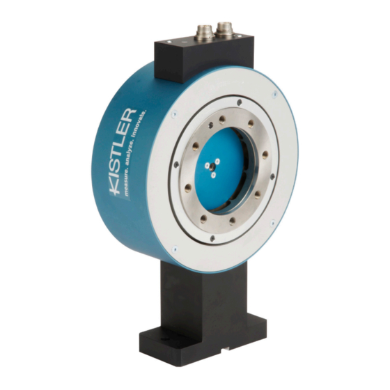
- Page 1 Instruction Manual Torque Measuring Flange Type 4510B… Compatible with Firmware-Version Stator: >V2.06 Rotor: >V1.9 ä 4510B_002-543e-01.14...
- Page 2 Instruction Manual Torque Measuring Flange Type 4510B… Compatible with Firmware-Version Stator: >V2.06 Rotor: >V1.9 ä 4510B_002-543e-01.14...
- Page 4 Torque measuring flange, as needed. The specifications in this manual can change at any time without prior notification. Kistler reserves the right to improve and to change the product for the purpose of technical progress without the obligation to inform persons and organizations as the result of such changes.
-
Page 5: Table Of Contents
Torque Measuring Flange, Type 4510B… Content Introduction ........................... 4 Important Information ........................5 Disposal Instructions for Electrical and Electronic Equipment ..........5 Application and Typical Features ....................6 Description of the Measuring System .................... 7 Mechanical Design ....................... 7 Electrical Design ........................7 4.2.1 Speed Measurement with 60 Pulses ................ - Page 6 Content RS-232C Communication ......................29 10.1 Interface Parameters ......................30 10.1.1 Conventions and Syntax ..................30 10.1.2 Error Messages ....................... 32 10.1.3 Measuring Rates, Reaction Times ................33 10.1.4 Requesting Torque Values Through RS-232C Command ........34 10.1.5 Requesting Torque Measuring Values via External Triggering ........ 35 10.2 Typical Measuring Sequence ....................
-
Page 7: Introduction
It will help you with the installation, maintenance, and use of this product. To the extent permitted by law Kistler does not accept any liability if this instruction manual is not followed or products other than those listed under Accessories are used. -
Page 8: Important Information
Do not discard old electronic instruments in municipal trash. For disposal at end of life, please return this product to an authorized local electronic waste disposal service or contact the nearest Kistler Instrument sales office for return instructions. 4510B_002-543e-01.14 Page 5... -
Page 9: Application And Typical Features
Torque Measuring Flange, Type 4510B… 3. Application and Typical Features Torque measuring flange with strain gage measuring system Digitalized wear-resistant measuring signal transmission Measurement of constant and variable torques Torque measurement on the rotating shaft Application in the laboratory, production and quality control ... -
Page 10: Description Of The Measuring System
Description of the Measuring System 4. Description of the Measuring System Mechanical Design The torque measuring flange consisting of a stator with support and a rotating rotor. On the measuring flange at the torsion section strain gages are arranged, as well as electronics with signal amplifier and A/D converter. - Page 11 Torque Measuring Flange, Type 4510B… Supply Stabilization Oscillator Rotary Modulator 11 ... 30 VDC (1 MHz) transmitter Control signal 3,5 ... 30 VDC AC/DC Control Strain gage Measurement range switch Micro 3,5 ... 30 VDC computer Gain 1:1 or 1:10 Torque Measuring Flange RS-232C A/D +...
-
Page 12: Speed Measurement With 60 Pulses
Description of the Measuring System 4.2.1 Speed Measurement with 60 Pulses The measuring of the speed of rotation is integrated in this torque measuring flange. This is realized by a pulse wheel with 60 pulses. A pulse wheel with 60 pulses. Raised sections on the wheel are detected with the aid of a magnetic sensor. -
Page 13: Electrical Connection Of Torque Measuring Flange
Torque Measuring Flange, Type 4510B… 5. Electrical Connection of Torque Measuring Flange Supply To supply torque measuring flange Type 4510B…, a supply voltage in the range of: 11 ... 30 VDC Direct Voltage is necessary.The direct voltage is supplied to the integrated 12 pin connector on pin F (+U ) and A (GND) . -
Page 14: Principle Of Galvanic Isolation In The Torque Measuring Flange
Electrical Connection of Torque Measuring Flange Torque measuring flange CoMo Torque Type 4700B… /VA 3600 Type 4704A… Screen (housing) stabilized power supply 11 … 30 VDC/min. 1A Fig. 5: Possible power supplier devices for Torque measuring flange Principle of Galvanic Isolation in the Torque Measuring Flange Torque Measuring Flange Internal voltages Supply... -
Page 15: Plug Allocation Of The 12 Pin Built-In Standard Connector A
Torque Measuring Flange, Type 4510B… Plug Allocation of the 12 pin Built-in Standard Connector A Plug Allocation of the 7 pin Built-in Standard Connector B Page 12 4510B_002-543e-01.14... -
Page 16: Measuring Range Selection
Electrical Connection of Torque Measuring Flange 5.4.1 Measuring Range Selection Must be: Option A1 (measuring range 1:10) or Option A2 (measuring range 1:5, technical data like 1:10) All specifications are for the measuring range 1:10 and 1:5. If the torque measuring sensor is additionally calibrated in the range of 1:10 at the factory, the requested range may be switched via PIN 1 and PIN 7. -
Page 17: Connection Diagram Standard Sensor
Torque Measuring Flange, Type 4510B… 5.4.3 Connection Diagram Standard Sensor Torque Measuring Supply and Sensor evaluation unit Type 4510B… Supply 11…30 VDC Ground U Torque output ±10 V AGND (0 V) Speed/angle output 5 V TTL (track A) 5 V TTL (track B) Counter DGND (0V) Control button... -
Page 18: Pin Allocation Of The Built-In Connector A And B (Standard)
Electrical Connection of Torque Measuring Flange 5.4.4 Pin Allocation of the Built-In Connector A and B (standard) Fig. 8: Connection diagram of torque measuring flange Type 4510B… with one or both options range selection/RS-232C interface to supply and evaluation units 4510B_002-543e-01.14 Page 15... -
Page 19: Connection Cable
Torque Measuring Flange, Type 4510B… 6. Connection Cable Type KSM072030-5 Technical Data Mat. No: 18008935 Connector 12 pin neg. – 12 pin pos. Length 5 (other length on request) Diameter mm 6 IP40 Deg. of protection to IEC/EN 60529 Type KSM124970-5 Technical Data Mat. -
Page 20: Laying Of The Measuring Cable
Connection Cable Technical Data Type KSM219710-5 Mat. No. 18008996 Connector 7 pin neg. – flying leads Length 5 (other length on request) Diameter mm 6 IP40 Deg. of protection to IEC/EN 60529 Laying of the Measuring Cable Do not lay parallel to power lines or control lines ... -
Page 21: Advice For Safe Electrical Installation
Torque Measuring Flange, Type 4510B… Advice for Safe Electrical Installation Connector Electronic box 0 Ω Stator ring of torque measuring 0 Ω flange Loading machine 0 Ω 0 Ω min. 16 Test stand bed Stator housing Shield Shield Fig. 10: Example for a safe electrical installation Please ensure correct functioning of the shield for the connection cable! -
Page 22: Mechanical Installation Of The Torque Measuring Flange
Mechanical Installation of the Torque Measuring Flange 7. Mechanical Installation of the Torque Measuring Flange There are different methods of installing the Torque measuring flange, depending on the application. Since very high lateral forces and bending moments may occur even at small axial displacement, the Torque measuring flange must always be mounted with couplings. -
Page 23: Installation Proposals
Torque Measuring Flange, Type 4510B… Installation Proposals 7.1.1 Shaft Tolerance The shaft on which the measuring flange is to be mounted must be manufactured with the tolerance h6 and must have a surface roughness Rt ≤16 µm. 7.1.2 Aligning Stator to Rotor Front edge of stator Front edge of rotor The front edge of the stator and that of the rotor must... -
Page 24: Installation And Removal Instructions For Shrinking Disks
Mechanical Installation of the Torque Measuring Flange 7.1.3 Installation and Removal Instructions for Shrinking Disks (Type HSD, Factory Stüwe) Montage Outer ring The shrinking disk are supplied ready to install. They should Clamping screws therefore not be dismantled prior to initial clamping. Inner ring 1. - Page 25 Torque Measuring Flange, Type 4510B… 12. The sensor is firmly seated. Increase the torque, then tighten the screws consecutively in a circle in several steps up to the maximum tightening torque M All clamping screws must be tightened until the front ends of the outer and inner ring align.
-
Page 26: Suggestion For Installation
Mechanical Installation of the Torque Measuring Flange Suggestion for Installation Clamping element (shrinking disk) Drive/brake Cardan shaft Measuring flange Specimen Fig. 11: Suggestion for installation with cardan shaft 7.2.1 Connection of Rotor, Fastening Bolts 4510B_002-543e-01.14 Page 23... -
Page 27: Electrical And Mechanical Commissioning
Errors in the Torque measuring flange electronics If the Torque measuring flange electronics do not function properly, the LED blinks red. Should this condition persist even after a new start of the Torque measuring flange, send it back to the factory (Kistler). Page 24 4510B_002-543e-01.14... -
Page 28: Adjusting And Calibrating The Torque Measuring Flange
Torque measuring flange mechanically overloaded Torque electronics defective, inform Kistler! Adjusting and Calibrating the Torque measuring flange Zero point and gain can only be set at the supply unit model VA 3600 Type 4704A… or the value processing unit. -
Page 29: Mechanical Calibration
Torque Measuring Flange, Type 4510B… Mechanical Calibration This requires a calibration device with lever arm and weights for torque generation. Calibration routine: Let the Torque measuring flange warm up for 10 minutes Load the Torque measuring flange with nominal torque and then unload it again ... -
Page 30: Calculation Example, Lever Arm Length
Electrical and Mechanical Commissioning 8.3.2 Calculation Example, Lever Arm Length ⋅ , whereby Torque Required lever arm length Required mass 9,80665 m/s² equals normal case acceleration (g depending on location) Example: m = 1 kg, M = 10 N·m ⋅ ⇒... -
Page 31: Making Torque Measurements
Torque Measuring Flange, Type 4510B… 9. Making Torque Measurements Switch on the Torque measuring flange When the device is switched on then the following steps are recommended to reach optimal measuring accuracy: START Sensor After the device is switched on the LED is blinking t ≈... -
Page 32: Rs-232C Communication
RS-232C Communication 10. RS-232C Communication Torque-equivalent values can be transmitted through the RS-232C interface. The following illustrates the sensor model regarding the RS-232C command structure of the Torque measuring flange Type 4510B… . Sensor model Signal acquisition and processing unit Torque and rotor MEASure temperature... -
Page 33: Interface Parameters
Torque Measuring Flange, Type 4510B… 10.1 Interface Parameters The RS-232C interface of the Torque measuring flange applies the following settings: Transmission rate (baudrate) 57 600 bits/second 8 Data bits 1 Stop bit No parity 10.1.1 Conventions and Syntax The Torque measuring flange responds through the RS- 232C interface only if it receives a command from the master (e.g. - Page 34 RS-232C Communication The termination is always effected with the characters <CR><LF> . A command for an inquiry ends with "?" (e.g. MEAS:TORQ?<CR><LF>). When a configuration transmission was successful, "0" is returned success message (e.g.. CONF:TEMP<CR><LF> Sensor: 0<CR><LF>). If a command was not accepted for different reasons, the Torque measuring flange returns a negative error value.
-
Page 35: Error Messages
Impossible to switch to the Calibrate the sensor in the –110 other measuring range other measuring range (send to Kistler) The error value –110 can only be sent with firmware version V2.00 or newer of the stator! Page 32 4510B_002-543e-01.14... -
Page 36: Measuring Rates, Reaction Times
RS-232C Communication 10.1.3 Measuring Rates, Reaction Times Depending on the configuration in the CONFiguration- and FORMat-function blocks different transmission rates are affected through the RS-232C interface (value queries per second). Please refer to the commands: (value query – configuration for the CONF MEAS-command) (define output format) -
Page 37: Requesting Torque Values Through Rs-232C Command
Torque Measuring Flange, Type 4510B… 10.1.4 Requesting Torque Values Through RS-232C Command Torque values can be requested with MEAS:TORQ? MEAS? (if previously configured with CONF:TORQ) After each inquiry only one torque-equivalent value is transmitted. For a later interpretation of the measuring curve the assignment of the positive nominal torque value and the digital output value is critical. -
Page 38: Requesting Torque Measuring Values Via External Triggering
RS-232C Communication Consequently: In 1:1 measuring range at 500 N·m a digital output swing of 26658 results, which is added to the digital offset value in unloaded condition. 10.1.5 Requesting Torque Measuring Values via External Triggering The external triggering with a digital signal can only be executed, if after start-up the Torque measuring flange has been initialized one time with the TRIGger command. -
Page 39: Typical Measuring Sequence
Torque Measuring Flange, Type 4510B… 10.2 Typical Measuring Sequence START After switching on the torque sensor allow the Sensor electronics of the torque sensor approx. 10 min to warm up. If desired all user data can be uploaded from Collect configuration the memory of the torque sensor for sensor Data from memory identification. -
Page 40: Configuration Commands
RS-232C Communication 10.3 Configuration Commands INPut ut-command group mainly influences the rotor electronics. The control signal can be activated or deactivated in this group. The gain changeover (selection between 1:1 and 1:10 range) is performed here as well. CONFiguration and FORMat In these command groups it is specified which value types and output formats should be defined. -
Page 41: Control Signal (Calibration Signal) On Or Off
Torque Measuring Flange, Type 4510B… 10.3.2 Control Signal (Calibration Signal) On or Off INP:CONT:<function> Parameter <function> = ON Control signal switched on Control signal switched off (normal operation) Query INP:CONT:STAT? Description With this command the control signal (colloquial: calibration signal) can be switched on or off, whereby the signal path between rotor- and stator electronics is INP:CONT:ON checked. -
Page 42: Value Query - Configuration For The Meas Command
RS-232C Communication 10.3.3 Value Query – Configuration for the MEAS Command CONF:<function> Parameter TORQ (torque value) <function> = TEMP (rotor temperature) Inquiry CONF? Description With this command the type of value query is specified. CONF:TORQ With and then with MEAS? a torque CONF:TEMP equivalent value can be evaluated. -
Page 43: Defining The Output Format
Torque Measuring Flange, Type 4510B… 10.3.4 Defining the Output Format FORM:DATA:<function> Parameter <function> =ASC (decimal output format) (hexadecimal output format) (binary output format) Inquiry FORM:DATA? Description The output format through the RS-232C interface regarding the torque measuring value can be influenced by FORM:DATA:ASC this command. -
Page 44: Determining The Trigger Mode
RS-232C Communication 10.3.5 Determining the Trigger Mode TRIG:MODE:<function> Parameter <function> = CONT (external trigger activated/deactivated control signal) MEAS (external trigger activates value transmission through RS-232C) Inquiry TRIG:MODE? Description This command specifies which action Torque measuring flange should perform at extern triggering TRIG:MODE:CONT (digital TTL-signal). -
Page 45: Determining Sensor Data
Torque Measuring Flange, Type 4510B… 10.3.6 Determining Sensor Data *IDN? Torque measuring flange identification IDN? MEM:<function>? Parameter <function> = General Torque measuring flange data Torque measuring flange type TYPE serial number MDAT date of manufacture CDAT calibration date calibration worker CWOR CUST customer name... - Page 46 Kistler Lorch GmbH _4510BStator_yyyy-mm-dd_Vx.xx_4510BRotor_yyyy-mm-dd_Vx.xx ------------------------- --------------------------- -------------------------- device identification header The header Kistler Lorch GmbH refers to a Kistler device firmware version of the stator electronic circuit The string chain 4510BStator_yyyy-mm-dd_Vx.xx refers to the date and the version number of the micro computer firmware of the stator electronic circuit ...
- Page 47 Torque Measuring Flange, Type 4510B… Example 2: Determining of general data The general data of a multi-calibrated torque measuring flange Type 4510B… with a ±10 V voltage output at ±100 N·m nominal torque should be transmitted via the RS-232C interface: PC command response of the torque ...
-
Page 48: Measuring Commands
RS-232C Communication 10.4 Measuring Commands 10.4.1 Transmitting Torque and Temperature Measuring Quantity MEAS<function> Parameter <function> = ? (Value transmission according to CONF-setting) :TORQ? (Torque value) :TEMP? (Rotor temp. value) Description With this command the torque measuring flange can transmit a torque equivalent value or the rotor temperature MEAS? through the RS-232C interface. - Page 49 Torque Measuring Flange, Type 4510B… FORM:DATA:HEX (decimal output format) CONF:TORQ (Configuration torque) D0AE (torque-equivalent value) D205 D275 CONF:TEMP (Configuration rotor temperature) MEAS? (Rotor temperature in °C) MEAS:TEMP? (Rotor temperature in °C) Page 46 4510B_002-543e-01.14...
-
Page 50: Maintenance
Maintenance 11. Maintenance Torque measuring flanges of the Type 4510B… series are nearly maintenance-free Precision applications: recalibrate the Torque measuring flange once a year (Calibration in the factory or with adequate calibration device) Control correct position of cable plugs monthly. ... -
Page 51: Technical Data
Torque Measuring Flange, Type 4510B… 13. Technical Data 13.1 Mechanical Basic Data 13.2 General Electrical Specifications Page 48 4510B_002-543e-01.14... -
Page 52: Electrical Measuring Data - Standard Measuring Range 1:1
Technical Data 13.3 Electrical Measuring Data – Standard Measuring Range 1:1 13.4 Electrical Measuring Data – Extended Measuring Range 1:5, 1:10 4510B_002-543e-01.14 Page 49... -
Page 53: Dimensions
Torque Measuring Flange, Type 4510B… 14. Dimensions Page 50 4510B_002-543e-01.14... - Page 54 Dimensions 4510B_002-543e-01.14 Page 51...
-
Page 55: Ordering Key And Accessories
Torque Measuring Flange, Type 4510B… 15. Ordering Key and Accessories Page 52 4510B_002-543e-01.14... -
Page 56: Declaration Of Conformity
Declaration of Conformity 16. Declaration of Conformity 4510B_002-543e-01.14 Page 53... -
Page 57: Index
Torque Measuring Flange, Type 4510B… 17. Index Mechanical Calibration ........27 Messwelle instandsetzen ........ 50 Adjusting and Calibrating....... 26 Application and Typical Features ...... 6 Ordering Key and Accessories ......55 Calibration Device .......... 27 Connection Diagram ........15 Plug Allocation ..........13 Control Signal ..........
Need help?
Do you have a question about the 4510B Series and is the answer not in the manual?
Questions and answers