
Related Manuals for SEI HO610200TX


Summary of Contents for SEI HO610200TX
- Page 1 HO610200TX Wall Mount Desk For assistance with assembly contact: Assembly Instruction Southern Enterprises Inc. Customer Service 1-800-633-5096 service@seidal.com www.seidal.com Page 1...
-
Page 2: Parts List
Wall Mount Desk Parts List Please check packaging for all parts and hardware before discarding. Unpack and lay parts on clean, padded surface like carpet or blanket. Check that you have all parts indicated. Call customer service if hardware is missing. - Page 3 Quantity Quantity of 28 of 8 Cam Lock Cam Lock Quantity Quantity of 10 of 6 Plastic anchor Screw 1/8”*1”L Quantity Quantity of 4 of 2 Bolt Handle Quantity Quantity of 36 of 4 Screw 1/8” *1/2L Ball Bearing Slide Quantity Quantity of 2...
- Page 4 Wall Mount Desk Assembly Instructions Firstly please disassemble Metal Slides(10) into Male Metal Slide(10) and Female Metal slide(10) as shown . Figure 1 Firstly please disassemble Metal Slides(11) into Male Metal Slide(11) and Female Metal Slide(11) as shown Figure 2 Attach Female Ball Bearing Slides (10/11) to Left Vertical Panel (D)and Right Vertical Panel(E)
- Page 5 Attach Female Ball Bearing Slides (10) to Left Side Panel (B) and Right Side Panel(C)with Wood Screw (9). Tighten screws with a phillips screwdriver (not included) Figure 4 Insert Cam Lock (3) into predrilled holes on Middle Bottom Panel (F). Screw Cam Bolt (2) into pre-drilled holes on Vertical Panel (D/E).
- Page 6 Insert Cam Lock (3) into predrilled holes on Side Bottom Panel (H). Screw Cam Bolt (2) into pre-drilled holes on pre-assembled unit from figure Attach Side Bottom Panel (H ) to pre-assembled unit from figure 5 by inserting Wood Dowel (1) & Cam Bolt (2) into corresponding pre-drilled holes until panels meet.
- Page 7 Attach Rail(I) to pre-assembled unit from figure 7 with Wood Dowel(1). Figure 8 Insert Cam Lock (3) into predrilled holes on pre-assembled unit from figure Screw Cam Bolt (2) into pre-drilled holes on Side Panel (B/C). Attach Side Panel (B/C ) to pre-assembled unit from figure 8 by inserting Wood Dowel (1) &...
- Page 8 Insert Cam Lock (3) into predrilled holes on pre-assembled unit from figure Screw Cam Bolt (2) into pre-drilled holes on Top Panel (A). Attach Top Panel (A ) to pre-assembled unit from figure 9 by inserting Wood Dowel (1) & Cam Bolt (2) into corresponding pre-drilled holes until panels meet.
- Page 9 Insert Cam Lock (4) into predrilled holes on Drawer Side Panel (K/L) Attach Drawer Side Panel (K/L ) to Drawer Front Panel(J) by inserting Cam Bolt (2) into corresponding pre-drilled holes until panels meet. Secure by rotating Cam Lock (4) clockwise with a Philips screwdriver.
- Page 10 Attached Handle(8) to drawer front with Bolt (7) Tighten bolt with Phillips screwdriver(not included) Attached drawer box’s into figure 10 unit, please make sure drawer box side’s male ball bearing slide into side panel’s female ball bearing slide, please try and make sure ball bearing slide in and out smoothly.
- Page 11 Attached keyboard into figure 14 unit, please make sure drawer box side’s male ball bearing slide into side panel’s female ball bearing slide, please try and make sure ball bearing slide in and out smoothly. Figure 16 Please mark a line on wall with pencil as shown Use a level on wall to insure line is level...
- Page 12 Using a power drill and 3/16/” drill bit, drill a hole through the wall at each marked hole location where screw (12) will not hit a stud in the wall. Then insert plastic anchors (6) into each hole and lightly tap anchors (6) with a hammer until they are securely flush with the face of the wall.
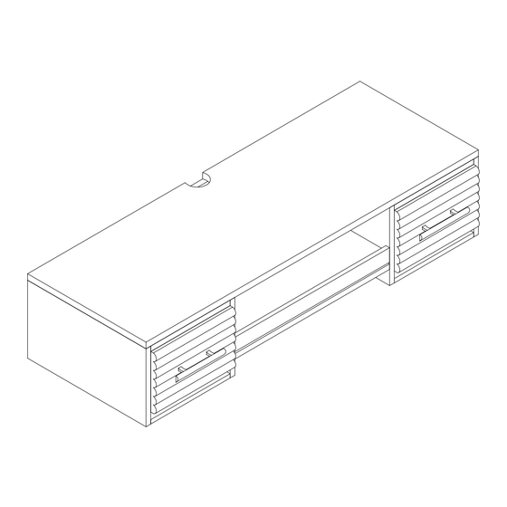
- Page 13 Use a level on table to insure table is level Figure 21 Now you wall mount desk is ready for use Max loading weight of top :20lbs Max loading weight of keyboard :10lbs Max loading weight of each drawer :10lbs Figure 22 Page 13...
-
Page 14: Parts Replacement Form
Parts Replacement Form Customer Information Name Address City/State/Zip Code Phone Number Please indicate where you purchased this item: Store/Website/Catalog Please indicate color/size/style number: Style No Parts Letter Parts Description Quantity Needed Please immediately examine this product carefully. Any request for missing parts or damage replacement must be received within 90 days of your receipt of the product.
Need help?
Do you have a question about the HO610200TX and is the answer not in the manual?
Questions and answers