Table of Contents
Advertisement
Quick Links
Advertisement
Table of Contents

Related Manuals for Neousys Technology SEMIL-1300GC Series


Summary of Contents for Neousys Technology SEMIL-1300GC Series
- Page 1 Neousys Technology Inc. SEMIL-1300GC Series User Manual Rev. 1.1...
-
Page 2: Table Of Contents
Service and Maintenance ...................... 8 ESD Precautions ........................8 Restricted Access Location ....................8 About This Manual ......................... 9 Introduction SEMIL-1300GC Series Overview ................10 SEMIL-1321GC Specifications ................. 11 SEMIL-1341GC Specifications ................. 13 Dimension ......................... 15 1.4.1 Superior View ....................15 1.4.2... - Page 3 Table of Contents 3.6.3 Wiring Ignition Signal ..................58 3.6.4 Configure your Windows system for Ignition Control ........59 Accessing the Rotary Switch .................. 60 Operation Modes of Ignition Power Control ............61 Reinstalling the Backplate ..................63 System Configuration BIOS Settings ......................
-
Page 4: Legal Information
For questions in regards to hardware/ software compatibility, customers should contact Neousys Technology Inc. sales representative or technical support. To the extent permitted by applicable laws, Neousys Technology Inc. shall NOT be responsible for any interoperability or compatibility issues that may arise when (1) products, software, or options not certified and supported;... -
Page 5: Contact Information
Neousys Technology Inc. (Taipei, Taiwan) 15F, No.868-3, Zhongzheng Rd., Zhonghe Dist., New Taipei City, 23586, Taiwan Tel: +886-2-2223-6182 Fax: +886-2-2223-6183 Email, Website Americas Neousys Technology America Inc. 3384 Commercial Avenue, Northbrook, IL 60062, USA (Illinois, USA) Tel: +1-847-656-3298 Email, Website China Neousys Technology (China) Ltd. -
Page 6: Copyright Notice
This manual is intended to be used as an informative guide only and is subject to change without prior notice. It does not represent commitment from Neousys Technology Inc. Neousys Technology Inc. shall not be liable for any direct, indirect, special, incidental, or consequential damages arising from the use of the product or documentation, nor for any infringement on third party rights. -
Page 7: Safety Precautions
Safety Precautions Safety Precautions ⚫ Read these instructions carefully before you install, operate, or transport the system. ⚫ Install the system or DIN rail associated with, at a sturdy location ⚫ Install the power socket outlet near the system where it is easily accessible ⚫... -
Page 8: Service And Maintenance
About This Manual Service and Maintenance ⚫ ONLY qualified personnel should service the system ⚫ Shutdown the system, disconnect the power cord and all other connections before servicing the system ⚫ When replacing/ installing additional components (expansion card, memory module, etc.), insert them as gently as possible while assuring connectors are properly engaged ESD Precautions ⚫... -
Page 9: About This Manual
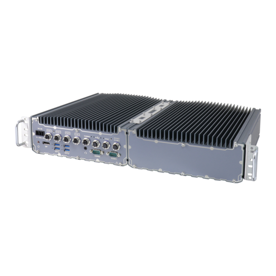
About This Manual This manual introduces Neousys Technology SEMIL-1300GC series, an extreme-rugged fanless GPU computer that supports NVIDIA® Tesla T4/ Quadro P2200/ RTX A2000 while featuring workstation-grade Intel® chipset and offers excellent passive thermal performance with M12 connectors for robust and cost-effectiveness. -
Page 10: Introduction
SEMIL-1300GC Series Introduction SEMIL-1300GC series is an extreme-rugged computer that supports an NVIDIA® Tesla T4/ Quadro P2200 inference accelerator. Featuring an Intel® work-station grade chipset to power a Xeon or 9 -Gen Core™ processor and coupled with M12 connectors, the system is design to meet the ever changing harsh environmental conditions that can no longer be met by traditional industrial computers. -
Page 11: Semil-1321Gc Specifications
SEMIL-1300GC Series SEMIL-1321GC Specifications System Platform Supporting Intel® Xeon® E and 9 -Gen CPU (LGA1151 socket - Xeon E 2176G (6C/12T) / 2278GE (8C/16T) / 2278GEL (8C/16T) Processor - Intel® Core™ i7-9700TE/ i7-9700E/ i7-8700T/ i7-8700 - Intel® Core™ i5-9500TE/ i5-9500E/ i5-8500T/ i5-8500 - Intel®... - Page 12 Shock EN-50155, CE/FCC Class A, according to EN 55032 & EN 55024 ** For optional 10GbE support, please contact Neousys Technology *** For Xeon E 2176G/ 2278GE, i7-9700E, and i7-8700 running at 65W mode, the highest operating temperature shall be limited to 50°C and thermal throttling may occur when sustained full-loading applied.
-
Page 13: Semil-1341Gc Specifications
SEMIL-1300GC Series SEMIL-1341GC Specifications System Platform Supporting Intel® Xeon® E and 9 -Gen CPU (LGA1151 socket - Xeon E 2176G (6C/12T) / 2278GE (8C/16T) / 2278GEL (8C/16T) Processor - Intel® Core™ i7-9700TE/ i7-9700E/ i7-8700T/ i7-8700 - Intel® Core™ i5-9500TE/ i5-9500E/ i5-8500T/ i5-8500 - Intel®... - Page 14 Shock EN-50155, CE/FCC Class A, according to EN 55032 & EN 55024 ** For optional 10GbE support, please contact Neousys Technology *** For Xeon E 2176G/ 2278GE, i7-9700E, and i7-8700 running at 65W mode, the highest operating temperature shall be limited to 50°C and thermal throttling may occur when sustained full-loading applied.
-
Page 15: Dimension
SEMIL-1300GC Series Dimension NOTE All measurements are in millimeters (mm). 1.4.1 Superior View... -
Page 16: Front Panel View
SEMIL-1300GC Series 1.4.2 Front Panel View 1.4.3 Side View 1.4.4 Bottom View... -
Page 17: Dimensions With Wall Mount Bracket
SEMIL-1300GC Series Dimensions with Wall Mount Bracket NOTE All measurements are in millimeters (mm). 1.5.1 Front View 1.5.2 Bottom View... -
Page 18: System Overview
Upon receiving and unpacking your system, please check immediately if the package contains all the items listed in the following table. If any item(s) are missing or damaged, please contact your local dealer or Neousys Technology. SEMIL-1300GC Packing List System... -
Page 19: Semil-1300Gc Front Panel
SEMIL-1300GC Series SEMIL-1300GC Front Panel Item Description Power button Use this button to turn on or shutdown the system. 3-pin terminal block (DC/ Compatible with DC power input from 8~48V, the terminal block is ignition input) also used for ignition signal input. -
Page 20: Power Button
SEMIL-1300GC Series 2.2.1 Power Button The power button is a non-latched switch for ATX mode on/off operation. To turn on the system, press the power button and the PWR LED should light-up green. To turn off the system, issuing a shutdown command in OS is preferred, or you can simply press the power button. -
Page 21: Displayport
SEMIL-1300GC Series 2.2.3 DisplayPort The system has a DisplayPort (DP) output which is a digital display interface that mainly connect video source and carry audio to a display device. When connecting a DisplayPort, it can deliver up to 4K UHD (4096 x 2304) in resolution. The system is designed to support passive DisplayPort adapter/ cable. -
Page 22: Poe+ Gigabit Ethernet Port
SEMIL-1300GC Series 2.2.4 PoE+ Gigabit Ethernet Port The system offers four PoE+ GbE ports via M12 X-coded connectors on the front panel. The port marked in green is implemented using Intel ® I219-LM controller that supports ® Wake-on-LAN and is also compatible with... -
Page 23: Usb3.1 Gen 1 Port
SEMIL-1300GC Series 2.2.5 USB3.1 Gen 1 Port The system’s USB 3.0 Gen 1 ports (5Gbps) come with screw-lock mechanisms and are implemented via native xHCI (eXtensible Host Controller Interface) controller. They are backward compatible with USB 2.0, USB 1.1 and USB 1.0 devices. Legacy USB is also... -
Page 24: Com Port 4
SEMIL-1300GC Series 2.2.7 COM Port 4 The COM 4 port is implemented using industrial-grade ITE8786 Super IO chip (-40 to 85°C) and provides up to 115200 bps baud rate. COM Port Pin Definition COM4 Pin# RS-232 Mode... -
Page 25: Usb2.0 Port
SEMIL-1300GC Series 2.2.8 USB2.0 Port The M12 A-coded connector provides two USB2.0 connections and are implemented via native xHCI (eXtensible Host Controller Interface) controller and are backward compatible with USB 1.1 and USB 1.0 devices. Legacy USB support is also provided so you can use USB keyboard/mouse in DOS environment. -
Page 26: Vga Port
SEMIL-1300GC Series 2.2.9 VGA Port VGA connector is the most common video display connection. The VGA output supports up to 1920x1200@60Hz resolution. To support VGA display output and achieve best VGA output resolution in Windows, you need to install corresponding graphics drivers. - Page 27 SEMIL-1300GC Series NOTE Please make sure your VGA cable includes SDA and SCL (DDC clock and data) signals for correct communication with monitor to get resolution/timing information. A cable without SDA/ SCL can cause blank screen on your VGA monitor due to incorrect resolution/timing output.
-
Page 28: Com Port 3
SEMIL-1300GC Series 2.2.10 COM Port 3 COM port 3 is implemented using industrial-grade ITE8786 Super IO chip (-40 to 85°C) and provide up to 115200 bps baud rate to communicate with external devices. COM3 is a software-configurable RS-232/422/485 port. The operation mode can be set in BIOS setup utility. -
Page 29: 2.2.11 Com1/ Com2 Port
SEMIL-1300GC Series 2.2.11 COM1/ COM2 Port The system provides two COM ports via an M12 A-coded connector for communicating with external devices. These COM ports are 3-wire RS-232 specifications and provide up to 115200 bps baud rate. Connector Pin Definition... -
Page 30: 2.2.12 Optional 10Gb Ethernet
SEMIL-1300GC Series 2.2.12 Optional 10Gb Ethernet The system offers an optional 10Gb Ethernet via M12 X-coded connector (in green) implemented using Intel® X550AT controller on the front panel. The port is backwards compatible with 5Gb, 2.5Gb, and Gb Ethernet connections. -
Page 31: Internal I/Os
SEMIL-1300GC Series Internal I/Os In addition to connectors on the enclosure panel, the system also provides internal expansion slots such as for hard drives, mini-PCIe, M.2 modules and access to ignition control rotary switch. 2.3.1 M.2 3042/ 3052 B Key Module Expansion Slot & Corresponding SIM Slots The system has an M.2 3042/ 3052 slot (indicated in... - Page 32 SEMIL-1300GC Series M.2 (B Key) Slot Pin Definition Pin # Signal Pin # Signal +3V3 +3V3 FULL_CARD_POWER_OFF_N USB_D+ W_DISABLE_N USB_D- Mechanical Key USB3.0-RX- USB3.0-RX+ UIM1-RESET UIM1-CLK USB3.0-TX- UIM1-DATA USB3.0-TX+ UIM1-PWR PERn0 / SATA-B+ UIM2-DET PERp0 / SATA-B- UIM2-DATA UIM2-CLK PETn0 / SATA-A-...
-
Page 33: 2242 E Key Module Expansion Slot
SEMIL-1300GC Series 2.3.2 M.2 2242 E Key Module Expansion Slot The system has an M.2 2230 E key socket for WiFi module installation. For SMA antenna installation, there are openings located at the rear of the chassis. - Page 34 SEMIL-1300GC Series M.2 2230 E Key Pin Definition Pin # Signal Pin # Signal +3V3 USB_D+ +3V3 USB_D- Mechanical Key PETP0 PETN0 PER P0 PER N0 REFCLK_P0 REFCLK_N0 CLKREQ# PERST# W_DISABLE# +3V3 +3V3...
-
Page 35: Mini-Pcie Expansion Slot (Mux With Msata)
SEMIL-1300GC Series 2.3.3 mini-PCIe Expansion Slot (mux with mSATA) The system has two mini-PCIe sockets mux with mSATA and there are plenty of off-the-shelf mini-PCIe modules with versatile capabilities. By installing a mini-PCIe module, your system can have expanded features such as 5G/4G, WIFI, GPS, CAN bus, analog frame grabber, etc. - Page 36 SEMIL-1300GC Series mini-PCIe slot definition Pin # Signal Pin # Signal WAKE# +3.3Vaux COEX1 COEX2 +1.5V CLKREQ# UIM_PWR UIM_DATA REFCLK- UIM_CLK REFCLK+ UIM_RESET UIM_VPP Mechanical Key Reserved* (UIM_C8) Reserved* (UIM_C4) W_DISABLE# PERST# PERn0 +3.3Vaux PERp0 +1.5V SMB_CLK PETn0 SMB_DATA PETp0...
-
Page 37: Ignition Control Rotary Switch
SEMIL-1300GC Series 2.3.4 Ignition Control Rotary Switch The ignition power control switch features multiple modes for pre and post ignition settings. Please refer to the section Ignition Power Control for details. -
Page 38: Installation
SEMIL-1300GC Series Installation For demonstration purposes, some illustrations will only show the accessible section (highlighted in blue) of the system for a clearer installation view. -
Page 39: Module & Sim Card Installation
SEMIL-1300GC Series M.2 Module & SIM card Installation The system comes with an E key M.2 2242/ 2252 and an B key M.2 3042/ 3052 expansion slot. To install or replace M.2 modules in the system, please refer to the following instructions: Disconnect all cable connections and shut down the system. - Page 40 SEMIL-1300GC Series Gently lift the panel and you will see the internal components. If hard drives are installed, disconnect the SATA/ power connector. Pull using the connector body, DO NOT pull on the cable!
- Page 41 SEMIL-1300GC Series Identify the slot locations of the M.2 slots. red rectangle is an M.2 2242 slot, blue rectangle is an M.2 3042/ 3052 slot, the two green rectangles are SIM card slots accessible by the module installed into the M.2 3042/ 3052 slot, the...
- Page 42 SEMIL-1300GC Series Remove an antenna hole on the enclosure and secure the antenna connector body. Antenna holes on enclosure Secure the connector body, coupling nut onto a antenna opening on the enclosure panel 10. Insert the corresponding SIM card before you install the mini-PCIe module.
- Page 43 SEMIL-1300GC Series 11. Gently tug all the cables into the enclosure and shut the bottom panel back on. 12. Secure the indicated screws in ascending order to complete the HDD installation procedure.
-
Page 44: Mini-Pcie Module Installation
SEMIL-1300GC Series mini-PCIe Module Installation To install or replace mini-PCIe modules in the system, please refer to the following instructions: Disconnect all cable connections and shut down the system. Turn the system upside-down and place it on a flat sturdy surface. - Page 45 SEMIL-1300GC Series Gently lift the panel and you will see the internal components. If hard drives are installed, disconnect the SATA/ power connector. Pull using the connector body, DO NOT pull on the cable!
- Page 46 SEMIL-1300GC Series Identify the slot locations of the mini-PCIe/ M.2 slots and their respective SIM slots. If you are installing 5G/ 4G mini-PCIe modules, please install the respective SIM cards first. Slide and lift SIM card holder Insert SIM card with pins facing up...
- Page 47 SEMIL-1300GC Series To install mini-PCIe/ M.2 module, simply insert the module into the slot on a 45 degree angle, press down and secure with a screw. Insert into slot on a 45 degree angle Secure the module with a screw Refer to the module’s manual and connect the antenna.
- Page 48 SEMIL-1300GC Series 11. Gently tug all the cables into the enclosure and shut the bottom panel back on. 12. Secure the screws indicated in blue, in ascending order to complete the HDD installation procedure.
-
Page 49: Hard Drive Installation
SEMIL-1300GC Series Hard Drive Installation To install or replace hard drives in the system, please refer to the following instructions: Disconnect all cable connections and shut down the system. Turn the system upside-down and place it on a flat sturdy surface. - Page 50 SEMIL-1300GC Series Gently lift the panel and you will see the internal components. If you are replacing existing HDD, disconnect the SATA/ power connector. Pull using the connector body, DO NOT pull on the cable! Disconnect the SATA/ power Remove the two screws on each side of the...
- Page 51 SEMIL-1300GC Series Place the hard drive in between the brackets and secure with screws on both sides. Repeat this step if you are installing a second HDD. Connect the SATA/ power cable onto the HDDs.
- Page 52 SEMIL-1300GC Series Gently tug all the cables into the enclosure and shut the bottom panel back on. Secure the screws indicated in blue, in ascending order to complete the HDD installation procedure.
-
Page 53: Wall-Mount Bracket Installation
SEMIL-1300GC Series Wall-mount Bracket Installation The system comes with wall-mount installation brackets. The four brackets are interchangeable and can be installed on any of the four locations designated for bracket installation. Please follow the procedures below to install the brackets. -
Page 54: Rack Mount Bracket Installation
SEMIL-1300GC Series Rack mount Bracket Installation The system comes with rack mount brackets for installation into server cabinets. Please follow the procedures below to install the rack mount brackets. You can find the two rack-mount brackets and screws in the accessory box. - Page 55 SEMIL-1300GC Series The grip (in green) can be found in the accessory box and is an optional installation item. Simply match the grip to the openings on the rack mount bracket and secure with M3 screws (in green) provided in the accessory box.
-
Page 56: Ignition Power Control
SEMIL-1300GC Series Ignition Power Control The ignition power control module for in-vehicle applications is a MCU-based implementation that monitors the ignition signal and reacts to turn on/off the system according to predefined on/off delay. Its built-in algorithm supports other features such as ultra-low power standby, battery-low protection, system hard-off, etc. -
Page 57: Additional Features Of Ignition Power Control
SEMIL-1300GC Series 3.6.2 Additional Features of Ignition Power Control In addition to the typical timing correlation, the ignition power control module offers additional features to provide additional reliability for in-vehicle applications. 1. Low battery detection The ignition power control module continuously monitors the voltage of DC input when the system is operational. -
Page 58: Wiring Ignition Signal
SEMIL-1300GC Series 3.6.3 Wiring Ignition Signal To have ignition power control for in-vehicle usage, you need to supply IGN signal to the system. The IGN input is located on the 3-pin pluggable terminal block (shared with DC power input). Below is the typical wiring configuration for in-vehicle applications. -
Page 59: Configure Your Windows System For Ignition Control
SEMIL-1300GC Series 3.6.4 Configure your Windows system for Ignition Control When applying ignition power control to your system, please make sure you’ve configured your Windows system to initiate a shutdown process when pressing the power button. By default, Windows 7/ 8/ 10 goes to sleep (S3) mode when power button is pressed. -
Page 60: Accessing The Rotary Switch
SEMIL-1300GC Series Accessing the Rotary Switch To access the rotary switch, please refer to the section Disassembling the System. Please power off the system and disconnect all cables connected to the system. Place the system upside-down on a steady surface. Remove the ten (10) screws indicated, and safe keep for later use. -
Page 61: Operation Modes Of Ignition Power Control
SEMIL-1300GC Series Operation Modes of Ignition Power Control You can use the rotary switch to configure the operation mode. The system offers 16 (0~15) operation modes with different power-on/power-off delay configurations. When rotary switch is set to mode 15 (0xF), the ignition power control is set to executed according to parameters configured in BIOS setup menu, which allows richer combination of power-on/ power-off delay and more detailed control parameters. - Page 62 SEMIL-1300GC Series ⚫ Mode 3 ~ Mode 12 Mode 3 ~ Mode 12 have various power-on delay and power-off delay. Each mode supports a hard-off timeout of 10 minutes. Mode Power-on Delay Power-off Delay Hard-off Timeout 10 seconds 10 seconds...
-
Page 63: Reinstalling The Backplate
SEMIL-1300GC Series Reinstalling the Backplate Once you have configured the ignition rotary switch, you are ready to re-secure the backplate. Before doing so, please make sure the O-ring is properly seated in the groove around the chassis edges. Please attached the backplate, and secure the plate using the original ten screws in the following incremental order, and at the torque force specified. -
Page 64: System Configuration
SEMIL-1300GC Series System Configuration BIOS Settings The system is shipped with factory-default BIOS settings meticulously programmed for optimum performance and compatibility. In this section, we’ll illustrate some of BIOS settings you may need to modify. Please always make sure you understand the effect of change before you proceed with any modification. -
Page 65: Com Port Configuration
SEMIL-1300GC Series 4.1.1 COM Port Configuration The system’s COM1/ COM2 ports support RS-232 (full-duplex) mode. Another option in BIOS called “Slew Rate” defines how sharp the rising/falling edge is for the output signal of COM1. To set COM port operating mode: Press F2when the system boots up to enter the BIOS setup utility. -
Page 66: Com Port High Speed Mode
SEMIL-1300GC Series 4.1.2 COM Port High Speed Mode The high speed mode of each COM port effectively allows for the port's baud rate generator to operate at 8x the speed with an effective baud rate of 921,600 bps (115,200 x 8). Please refer to the following instructions on how to enable the high speed mode for your COM port (COM1 used as an example). -
Page 67: Delay For Peg Initialization
SEMIL-1300GC Series 4.1.3 Delay for PEG Initialization This setting offers delay in milliseconds for PEG port initialization and PCI enumeration. By increasing the delay value, it may eliminate compatibility issue(s) with some PCIe add-on cards. To set PEG delay in milliseconds: 1. -
Page 68: Sata Configuration
SEMIL-1300GC Series 4.1.4 SATA Configuration The SATA controller of your system supports two (2) operating modes: AHCI and Intel RST Premium With Intel Optane System Acceleration mode. The AHCI mode, which exposes SATA's advanced capabilities such as hot swapping and native command queuing, is supported in several later version of operating systems. - Page 69 SEMIL-1300GC Series To set SATA controller mode: When system boots up, press F2 to enter BIOS setup utility. Go to [Advanced] > [SATA Configuration]. Highlight the SATA, mSATA or M.2 port you wish to set and press ENTER to bring up setting options.
-
Page 70: Tpm Availability
SEMIL-1300GC Series 4.1.5 TPM Availability Trusted Platform Module (TPM) is a hardware-based cryptoprocessor to secure hardware by integrating cryptographic keys into devices. The system is designed with on-board TPM 2.0 module. As TPM 2.0 requires 64-bit Windows 10 with UEFI boot mode, it is enabled in BIOS by default. -
Page 71: Auto Wake On S5
SEMIL-1300GC Series 4.1.6 Auto Wake on S5 When the system is set to operate in S5 state, the user can specify a time to turn on the system, daily or monthly. Value Option Description Auto Wake on S5 Disabled The system does not turn on when operating in state S5. -
Page 72: Power On After Power Failure Option
SEMIL-1300GC Series 4.1.7 Power On After Power Failure Option This option defines the behavior of system series when DC power is supplied. Value Description S0 – Power On System is powered on when DC power is supplied. S5 – Power Off System is kept in off state when DC power is supplied. -
Page 73: Power & Performance (Cpu Sku Power Configuration)
SEMIL-1300GC Series 4.1.8 Power & Performance (CPU SKU Power Configuration) The system supports various 8th Gen Coffee Lake LGA1151 CPUs. A unique feature, “SKU Power Config” is implemented in BIOS to allow users to specify user-defined SKU power limit. Although the system is designed to have best thermal performance with CPUs of 35W TDP, you can install a 65W CPU and limit its SKU power (to 35W) to obtain more computing power. -
Page 74: Wake On Lan Option
SEMIL-1300GC Series 4.1.9 Wake on LAN Option Wake-on-LAN (WOL) is a mechanism which allows you to turn on your System series via Ethernet connection. To utilize Wake-on-LAN function, you have to enable this option first in BIOS settings. Please refer “Powering On Using... -
Page 75: 4.1.10 Boot Menu
SEMIL-1300GC Series 4.1.10 Boot Menu The Boot menu in BIOS allows you to specify the system’s boot characteristics by setting bootable device components (boot media) and method. Or, you may press F12 upon system start up and select a device you wish boot from. - Page 76 SEMIL-1300GC Series capability eXecution Environment (PXE) is not supported Enabled By enabling the PXE boot, one can choose to boot via I219 Only/ I210 Only or All NICs. Add Boot Options First Newly detected boot media are placed at the top of the boot order.
-
Page 77: Boot Type (Legacy/ Uefi)
SEMIL-1300GC Series 4.1.11 Boot Type (Legacy/ UEFI) The system supports both Legacy and Unified Extensible Firmware Interface (UEFI) boot modes. UEFI is a specification proposed by Intel to define a software interface between operating system and platform firmware. Most modern operating systems, such as Windows 7/ 8/ 10 and Linux support both Legacy and UEFI boot modes. -
Page 78: 4.1.12 Boot Option For Newly Added Device
SEMIL-1300GC Series 4.1.12 Boot Option for Newly Added Device The “Add Boot Options” allow you to determine whether a newly added device (eg. USB flash disk) is to boot as the first device to boot or the last in the boot sequence. -
Page 79: 4.1.13 Watchdog Timer For Booting
SEMIL-1300GC Series 4.1.13 Watchdog Timer for Booting The watchdog timer secures the boot process by means of a timer. Once the timer expires, a reset command is issued to initiate another booting process. There are two options in BIOS menu, “Automatically after POST” and “Manually after Entering OS”. -
Page 80: 4.1.14 Selecting Legacy/ Uefi Boot Device
SEMIL-1300GC Series 4.1.14 Selecting Legacy/ UEFI Boot Device When you wish to set a designated boot device, you may set it as the first device to boot in Legacy or UEFI Boot Device setting. Or if you wish to manually select a boot device,... -
Page 81: Amt Configuration
SEMIL-1300GC Series AMT Configuration Intel® AMT (Active Management Technology) is a hardware-based technology for remotely managing target PCs via Ethernet connection. The system supports AMT function via its Ethernet port implemented with Intel I219-LM. Prior to using AMT to remotely control the system, you need to configure AMT password and network settings. -
Page 82: Raid Volume Configuration
SEMIL-1300GC Series RAID Volume Configuration To set up a RAID 0 or 1 volume in Legacy or UEFI mode, you need to have at least two hard drives or SSDs installed. The system supports RAID configurations in RAID 0 (striping) or RAID 1 (mirror) mode. Users can select the configuration that best suit their needs with RAID 0 (striping) mode offering better hard drive read/ write performances while RAID 1 (mirror) offers better data security. - Page 83 SEMIL-1300GC Series Go to [Boot] > highlight [Legacy Boot Type] and press ENTER to set boot type. Press F10 to "Exit Saving Changes" and reboot the system. When the system reboots, press [Ctrl + I] to enter the RAID configuration utility.
- Page 84 SEMIL-1300GC Series The following screen allows you to enter the Name of the RAID volume you wish to create. Enter a name and press ENTER to access the RAID Level setting. For RAID Level, use the up and down arrow key to select between RAID0 (Stripe) or RAID1 (Mirror) settings.
- Page 85 SEMIL-1300GC Series 9. For Stripe Size, use the up and down arrow key to select between 4KB, 8KB, 16KB, 32KB, 64KB, 128KB for your RAID volume stripe size and press ENTER to access the Capacity setting. *RAID1(Mirror) does not offer Stripe Size options.
- Page 86 SEMIL-1300GC Series 11. Reviewed your settings and if you wish to change any setting(s), you will need to press [ESC] and start again from Step 5.If all settings are correct and you wish to continue, with “Create Volume” highlighted, press ENTER to begin creating the RAID volume.
- Page 87 SEMIL-1300GC Series 13. Once the RAID volume has been created, the configuration utility will bring you back to the main screen showing the RAID volume and their member disks. 14. The above process was to create a RAID-0 volume. If you wish to create a RAID-1...
-
Page 88: Uefi Mode Raid Configuration
SEMIL-1300GC Series 4.3.2 UEFI Mode RAID Configuration To enable RAID functionality in UEFI mode: 1. When system boots up, press F2 to enter BIOS setup utility. 2. Go to [Advanced] > [SATA And RST Configuration] > [SATA Mode Selection] >... - Page 89 SEMIL-1300GC Series 3. Go to [Boot], highlight [UEFI Boot Type] and press ENTER to set boot type. 4. Press F10 to “Exit Saving Changes” and reboot the system. 5. When the system reboots, press [F3] to enter the Configuration Utility.
- Page 90 SEMIL-1300GC Series 7. The following screen shows Non-RAID physical disks and the option “Create RAID Volume”. Highlight “Create RAID Volume” and press ENTER to begin creating your RAID volume.
- Page 91 SEMIL-1300GC Series 8. The Name option allows you to name your RAID volume. Press ENTER when ready to go to the next option.
- Page 92 SEMIL-1300GC Series 9. The RAID Level option allows you to select RAID-0 (stripping) or RAID-1 (mirror) for your RAID volume. Press ENTER when ready.
- Page 93 SEMIL-1300GC Series 10. The Select Disks option allows you to select disk drives for your RAID volume. Highlight a drive and press ENTER, use up/ down arrow keys to highlight “x” and press ENTER to confirm the selection. A minimum of two disk drives must be selected...
- Page 94 SEMIL-1300GC Series 11. The Stripe Size option allows you to configure the stripe size of your RAID volume. Available stripe sizes are 4KB, 8KB, 16KB, 32KB, 64KB, 128KB, use the up and down arrow keys to highlight and press ENTER to confirm the stripe size selection.
- Page 95 SEMIL-1300GC Series 12. The Capacity (MB) option allows you to configure the storage capacity of your RAID volume. By default, the full storage capacity will be applied. Once you have entered a capacity, press ENTER to confirm.
- Page 96 SEMIL-1300GC Series 13. The Create Volume option is the final step in the volume creation process. Highlight “Create Volume” and press ENTER to begin creating your RAID volume base on the settings you just configured.
- Page 97 SEMIL-1300GC Series 14. A summary and status of the RAID volume will be shown when the RAID volume is successfully created. 15. Press F10 to save and Esc to exit the Intel® Rapid Storage Technology configuration page. NOTE The above process was to create a RAID-0 volume. If you wish to create a RAID-1...
-
Page 98: Os Support And Driver Installation
SEMIL-1300GC Series OS Support and Driver Installation Operating System Compatibility The system support most operating system developed for Intel® x86 architecture. The following list contains the operating systems which have been tested by Neousys Technology. ⚫ Microsoft Window 10 (x64) ⚫... -
Page 99: Install Drivers Automatically
SEMIL-1300GC Series Install Drivers Automatically The system comes with a “Drivers & Utilities” DVD that offers “one-click” driver installation process. It automatically detects your Windows operating system and installs all necessary drivers for you system with a single click. 5.2.1 Install Drivers Automatically To install drivers automatically, please refer to the following procedures. -
Page 100: Install Drivers Manually
SEMIL-1300GC Series Install Drivers Manually You can also manually install each driver for the system. Please note when installing drivers manually, you need to install the drivers in the following sequence mentioned below. 5.3.1 For Windows 10 (x64) The recommended driver installation sequence is C hipset driver (x:\Driver_Pool\Chipset_CFL\Win_10_64\SetupChipset.exe) -
Page 101: Driver Installation For Watchdog Timer Control
SEMIL-1300GC Series Driver Installation for Watchdog Timer Control Neousys provides a driver package which contains function APIs for watchdog timer, digital I/ O, per-port PoE power on/off control and other platform-related functions. You should install the driver package (WDT_DIO_Setup.exe) in prior to use these functions. -
Page 102: Intel ® Optane Tm Memory Bios Setup And Driver Installation
SEMIL-1300GC Series ® Intel Optane Memory BIOS Setup and Driver Installation ® The system is compatible with Intel Rapid Storage Technology that supports the ® installation of Intel Optane memory to significantly boost traditional hard disk drive memory is Intel® RST’s latest system read and write performances. - Page 103 SEMIL-1300GC Series Go to “SATA Mode Selection”, press the Enter key to bring up options, select “Intel RST Premium With Intel Optane System Acceleration” and press ENTER to select the option.
- Page 104 SEMIL-1300GC Series Go to “M.2 2280 NVMe Storage Device” and press the Enter key to bring up the selection, select “RST Controlled” and press the Enter key to select the option. Press F10 to save and exit, and allow the system to boot into Windows.
- Page 105 SEMIL-1300GC Series Follow the 6 step setup procedure as instructed.
- Page 106 SEMIL-1300GC Series Check the “I accept the terms in the License Agreement” box and click on “Next >” to continue the installation process.
- Page 107 SEMIL-1300GC Series When done, click on “Finish” and restart the system.
- Page 108 SEMIL-1300GC Series 10. Upon system restart, the following initialization screen will appear. Click on Next to continue. 11. In the Setup section, you will see your Intel® Optane™ memory drive and compatible drive(s) that can be accelerated. Click on the downward arrow to bring...
- Page 109 SEMIL-1300GC Series 12. The data backup warning will appear, please backup any data you may have stored on your Intel® Optane™ memory module before proceeding. Check the box “Erase all data on Intel® Optane™ memory module” and click on Continue.
- Page 110 SEMIL-1300GC Series 14. Upon system restart, a successful enablement message will appear to indicate the Intel® Optane™ memory module has been enable successfully. 15. Once enabled, the RST software Setup section should show your configuration information.
-
Page 111: Appendix A: Using Wdt & Dio
In this section, we’ll illustrate how to use the function library provided by Neousys to program the WDT functions. Currently, WDT driver library supports Windows 10 x64 and WOW64 platform. For other OS support, please contact Neousys Technology for further information. -
Page 112: Wdt And Dio Library Installation
SEMIL-1300GC Series WDT and DIO Library Installation To setup WDT & DIO Library, please follow instructions below. 1. Execute WDT_DIO_Setup.2.3.0.exe and the following dialog appears. 2. Click “Next >” and specify the directory of installing related files. The default directory... - Page 113 SEMIL-1300GC Series 3. Once the installation has finished, a dialog will appear to prompt you to reboot the system. The WDT & DIO library will take effect after the system has rebooted. 4. When programming your WDT or DIO program, the related files are located in...
-
Page 114: Wdt Function Reference
SEMIL-1300GC Series WDT Function Reference InitWDT Syntax BOOL InitWDT(void); Description: Initialize the WDT function. You should always invoke InitWDT() before set or start watchdog timer. Parameter None Return Value TRUE: Successfully initialized FALSE: Failed to initialize Usage BOOL bRet = InitWDT() -
Page 115: Startwdt
SEMIL-1300GC Series StartWDT Syntax BOOL StartWDT(void); Description Starts WDT countdown. Once started, the WDT LED indicator will begin blinking. If ResetWDT() or StopWDT is not invoked before WDT countdowns to 0, the WDT expires and the system resets. Parameter None... -
Page 116: Appendix B: Poe On/ Off Control
SEMIL-1300GC Series Appendix B: PoE On/ Off Control The system offers 802.3at PoE+ ports with a unique feature to allow users manually turn on or off the power supply of each PoE port. This can be function can be useful in power device (PD) fault-recovery or power reset. -
Page 117: Enablepoeport
SEMIL-1300GC Series EnablePoEPort Syntax BOOL EnablePoEPort (BYTE port); Description Turn on PoE power of designated PoE port. Parameter port BYTE value specifies the index of PoE port. Please refer to the following illustration, port should be a value of 1 ~ 4. -
Page 118: Disablepoeport
SEMIL-1300GC Series DisablePoEPort Syntax BOOL DisablePoEPort (BYTE port); Description Turn off PoE power of designated PoE port Parameter port BYTE value specifies the index of PoE port. Please refer to the following illustration, port should be a value of 1 ~ 4...
Need help?
Do you have a question about the SEMIL-1300GC Series and is the answer not in the manual?
Questions and answers