
Related Manuals for Neousys Technology SEMIL-2000 Series


Summary of Contents for Neousys Technology SEMIL-2000 Series
- Page 1 | 866-412-6278 | info@coastipc.com Neousys Technology Inc. SEMIL-2000 Series User Manual v1.0 Rev032724...
-
Page 2: Table Of Contents
Restricted Access Location ....................8 About This Manual ......................... 9 Introduction SEMIL-2000GC Specifications ................. 11 SEMIL-2000 Specifications ..................13 System Overview SEMIL-2000 Series Packing List................15 SEMIL-2000GC Series Front Panel................16 2.2.1 Gb Ethernet....................... 17 2.2.2 DC-IN Connector ....................18 2.2.3... - Page 3 Table of Contents Configure your Windows system ................73 System Configuration BIOS Settings ......................74 5.1.1 COM1/ 2/ 3 Port Configuration ................75 5.1.2 COM 4 Port Configuration ................. 76 5.1.3 Delay for PEG Initialization ................78 5.1.4 TPM Availability ....................79 5.1.5 Power &...
-
Page 4: Legal Information
For questions in regards to hardware/ software compatibility, customers should contact Neousys Technology Inc. sales representative or technical support. To the extent permitted by applicable laws, Neousys Technology Inc. shall NOT be responsible for any interoperability or compatibility issues that may arise when (1) products, software, or options not certified and supported;... -
Page 5: Contact Information
Neousys Technology Inc. (Taipei, Taiwan) 15F, No.868-3, Zhongzheng Rd., Zhonghe Dist., New Taipei City, 23586, Taiwan Tel: +886-2-2223-6182 Fax: +886-2-2223-6183 Email, Website Americas Neousys Technology America Inc. 3384 Commercial Avenue, Northbrook, IL 60062, USA (Illinois, USA) Tel: +1-847-656-3298 Email, Website China Neousys Technology (China) Ltd. -
Page 6: Copyright Notice
This manual is intended to be used as an informative guide only and is subject to change without prior notice. It does not represent commitment from Neousys Technology Inc. Neousys Technology Inc. shall not be liable for any direct, indirect, special, incidental, or consequential damages arising from the use of the product or documentation, nor for any infringement on third party rights. -
Page 7: Safety Precautions
Safety Precautions Safety Precautions ⚫ Read these instructions carefully before you install, operate, or transport the system. ⚫ Install the system or DIN rail associated with, at a sturdy location ⚫ Install the power socket outlet near the system where it is easily accessible ⚫... -
Page 8: Service And Maintenance
Service and Maintenance/ ESD Precautions Service and Maintenance ⚫ ONLY qualified personnel should service the system ⚫ Shutdown the system, disconnect the power cord and all other connections before servicing the system ⚫ When replacing/ installing additional components (expansion card, memory module, etc.), insert them as gently as possible while assuring connectors are properly engaged ESD Precautions... -
Page 9: About This Manual
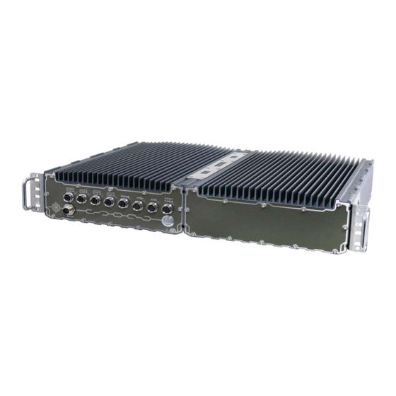
About This Manual About This Manual This user manual introduces Neousys Technology SEMIL-2000 series, an IP69K waterproof extreme-rugged fanless GPU computer that supports NVIDIA® Tesla L4 while featuring workstation-grade Intel® chipset and offers excellent passive thermal performance with M12 connectors for robust and cost-effectiveness. -
Page 10: Introduction
SEMIL-2000 Series Introduction SEMIL-2000GC is an extreme-rugged IP69K dustproof and waterproof edge AI platform in a 2U 19" rack-mount form factor. SEMIL- 2000GC incorporates Neousys' best-in-class thermal design to ensure fanless maximum GPU performance in wide range -40°C to 70°C temperatures. The system is also integrated with an NVIDIA® L4 GPU that offers up to 2.5 times the performance over Tesla T4. -
Page 11: Semil-2000Gc Specifications
SEMIL-2000 Series SEMIL-2000GC Specifications System Platform Supporting Intel® 13th-Gen Core™ Supporting Intel® 12th-Gen Core™ CPU CPU (LGA1700 socket, 65W/ 35W (LGA1700 socket, 65W/ 35W TDP) TDP) - Intel® Core™ i9-12900E/ i9-12900TE - Intel® Core™ i9-13900E/ - Intel® Core™ i7-12700E/ i7-12700TE i9-13900TE - Intel®... - Page 12 SEMIL-2000 Series Ignition Control Built-in ignition power control (IGN/ GND signal via M12 L-coded connector) For reference only, actual consumption may vary depending on configuration. With i9-13900E with NVIDIA L4, tested GPU-burn, burn-in PL2 Max. Power 35W mode: 192W (Max.) @ 24V Consumption 35W mode: 194W (Max.) @ 48V...
-
Page 13: Semil-2000 Specifications
SEMIL-2000 Series SEMIL-2000 Specifications System Platform Supporting Intel® 13th-Gen Core™ Supporting Intel® 12th-Gen Core™ CPU CPU (LGA1700 socket, 65W/ 35W (LGA1700 socket, 65W/ 35W TDP) TDP) - Intel® Core™ i9-12900E/ i9-12900TE - Intel® Core™ i9-13900E/ - Intel® Core™ i7-12700E/ i7-12700TE i9-13900TE - Intel®... - Page 14 SEMIL-2000 Series Ignition Control Built-in ignition power control (IGN/ GND signal via M12 L-coded connector) For reference only, actual consumption may vary depending on configuration. With i9-13900E, tested burn-in PL2 Max. Power 35W mode: 114W (Max.) @ 24V Consumption 35W mode: 119W (Max.) @ 48V 65W mode: 151W (Max.) @ 24V...
-
Page 15: System Overview
Upon receiving and unpacking your system, please check immediately if the package contains all the items listed in the following table. If any item(s) are missing or damaged, please contact your local dealer or Neousys Technology. SEMIL-2000 Series Packing List... -
Page 16: Semil-2000Gc Series Front Panel
SEMIL-2000 Series SEMIL-2000GC Series Front Panel Item Description M12 X-coded 1Gb Ethernet via Intel i219-LM DC-in 8V to 48V DC input, with reverse polarity protection (M12 L-coded) The M12 X-coded 2.5Gb Ethernet ports are backward compatible with 2.5GbE & 1GbE and offer Power over Ethernet (PoE) to provide both data PoE+ connection and electric power to devices (eg. -
Page 17: Gb Ethernet
SEMIL-2000 Series 2.2.1 Gb Ethernet The system offers one Gb Ethernet port implemented Intel i219. It supports Wake on LAN and is also compatible with Intel® AMT (Active Management Technology) to support advanced features such as remote SOL desktop and remote on/ off control. -
Page 18: Dc-In Connector
SEMIL-2000 Series 2.2.2 DC-IN Connector The system accepts a wide range of DC power input from 8V to 48V with reverse polarity protection via a M12 L-coded connector. The M12 L-coded connectors offer COTS availability and ultra-rugged connection reliability when wiring DC power. -
Page 19: Gb Ethernet And Poe+ Port
SEMIL-2000 Series 2.2.3 2.5 Gb Ethernet and PoE+ Port The system offers 2.5Gb ports with PoE+ via M12 X-coded connectors on the front panel. Power over Ethernet (PoE) supplies electrical power and data on a CAT-5/CAT-6 Ethernet cable. Acting as a PoE PSE (Power Sourcing Equipment), compliant with IEEE 802.3at, each PoE port delivers up to 25.5W to a Powered Device (PD). -
Page 20: Canbus Port 1/ 2
SEMIL-2000 Series 2.2.4 CANbus Port 1/ 2 CAN bus is a robust industrial bus with a pair of differential signals and is commonly used in various industrial and in-vehicles applications. The CAN bus port supports CAN2.0A and CAN2.0B up to 1Mbps. -
Page 21: Com3/ Com4 Port
SEMIL-2000 Series 2.2.5 COM3/ COM4 Port The system provides an isolated COM3 port (RS-232) and a COM4 port (RS-422/ 485) to communicate with external devices. Connector Pin Definition M12 Panel side M12 Cable end COM cable Signal Signal M12 panel pin... -
Page 22: Com1/ Com2 Port
SEMIL-2000 Series 2.2.6 COM1/ COM2 Port The system provides two isolated COM ports via an M12 A-coded connector for communicating with external devices. COM 1 and 2 ports are 3-wire RS-232 specifications and provide up to 115200 bps baud rate. -
Page 23: Usb2.0 Port
SEMIL-2000 Series 2.2.7 USB2.0 Port The USB2.0 ports are implemented via native xHCI (eXtensible Host Controller Interface) controller and are backward compatible with USB 1.1 and USB 1.0 devices. Legacy USB support is also provided so you can use USB keyboard/mouse in DOS environment. -
Page 24: 10Gb Ethernet
SEMIL-2000 Series 2.2.8 10Gb Ethernet The system offers two 10Gb Ethernet ports supporting Wake-on-LAN via M12 X-coded connector implemented using Intel® X550AT controller on the front panel. The port is backwards compatible with 5Gb, 2.5Gb, and Gb Ethernet connections. Connector Pin Definition... -
Page 25: Type-C Usb 3.2 Gen 1 Ports/ Displayport
SEMIL-2000 Series 2.2.9 Type-C USB 3.2 Gen 1 Ports/ DisplayPort The system’s USB 3.2 Gen1x1 type-C port offers up to 5Gbps of data transfer bandwidth, and is implemented via the native xHCI (eXtensible Host Controller Interface) controller. The port is backward compatible with USB3.2 Gen.1 USB 2.0, USB 1.1 and USB 1.0 devices via a USB hub (not included) to connect to external devices. -
Page 26: 2.2.10 Power Button
SEMIL-2000 Series 2.2.10 Power Button The power button is a non-latched switch for ATX mode on/off operation. To turn on the system, press the power button and the PWR LED should light-up. To turn off the system, issuing a shutdown command in OS is preferred, or you can simply press the power button. -
Page 27: Internal I/Os
Installing after-sales internal modules on your own may affect its waterproof capabilities and is not recommended. If you must install internal modules after purchase, please consult your sales representative as you may need to return the system to Neousys Technology or an authorized SEMIL distributor for processing to retain waterproof capability. -
Page 28: Mini-Pcie Expansion Slot
SEMIL-2000 Series 2.3.1 mini-PCIe Expansion Slot NOTE For demonstration purposes, only the compartment with accessible expansion modules will be shown. The system has three mini-PCIe sockets. There are plenty of off-the-shelf mini-PCIe modules with versatile capabilities. By installing a mini-PCIe module, your system can have expanded features such as 5G/4G, WIFI, GPS, CAN bus, analog frame grabber, etc. - Page 29 SEMIL-2000 Series mini-PCIe slot definition Pin # Signal Pin # Signal WAKE# +3.3Vaux COEX1 COEX2 +1.5V CLKREQ# UIM_PWR UIM_DATA REFCLK- UIM_CLK REFCLK+ UIM_RESET UIM_VPP Mechanical Key Reserved* (UIM_C8) Reserved* (UIM_C4) W_DISABLE# PERST# PERn0 +3.3Vaux PERp0 +1.5V SMB_CLK PETn0 SMB_DATA PETp0...
-
Page 30: 2230 E Key Slot
SEMIL-2000 Series 2.3.2 M.2 2230 E Key Slot The system has an M.2 2230 E key socket that offers PCIe Gen3 x1 and USB2.0 signal for WiFi module installation. - Page 31 SEMIL-2000 Series M.2 2230 E Key Pin Definition Pin # Signal Pin # Signal +3V3 +3V3 USB_D+ USB_D- Mechanical Key PETP0 PETN0 PER P0 PER N0 REFCLK_P0 REFCLK_N0 CLKREQ# PERST# W_DISABLE# +3V3 +3V3...
-
Page 32: 2242/ 3052 B Key Slot
SEMIL-2000 Series 2.3.3 M.2 2242/ 3052 B Key Slot Underneath the heat-spreader, the system has an M.2 2242/ 3052 slot (indicated in blue) with 5G/ 4G SIM slots (indicated in red). A copper standoff is provided for you to secure... - Page 33 SEMIL-2000 Series M.2 (B Key) Slot Pin Definition Pin # Signal Pin # Signal +3V3 +3V3 FULL_CARD_POWER_OFF_N USB_D+ W_DISABLE_N USB_D- Mechanical Key USB3.0-RX- USB3.0-RX+ UIM1-RESET UIM1-CLK USB3.0-TX- UIM1-DATA USB3.0-TX+ UIM1-PWR PERn0 / SATA-B+ UIM2-DET PERp0 / SATA-B- UIM2-DATA UIM2-CLK PETn0 / SATA-A-...
-
Page 34: 2280 M Key Slot (Pcie Gen4 X4) For Nvme Ssd
SEMIL-2000 Series 2.3.4 M.2 2280 M Key Slot (PCIe Gen4 x4) for NVMe SSD Underneath the heat-spreader, the system has a Gen4 x4 PCIe M.2 2280 slot for you to install an NVMe SSD. The M.2 NVMe SSD offers significantly better system... - Page 35 SEMIL-2000 Series M.2 (M Key) Slot Pin Definition Pin # Signal Pin # Signal +3V3 +3V3 PERN3 PERP3 DAS/DSS_N PETN3 +3V3 PETP3 +3V3 +3V3 PERN2 +3V3 PERP2 PETN2 PETP2 PERN1 PERP1 PETN1 PETP1 PERn0 PERp0 PETn0 PETp0 PERST_N REFCLKN REFCLKP...
-
Page 36: System Installation
SEMIL-2000 Series System Installation Before disassembling the system enclosure and installing components and modules, please make sure you have done the following: ⚫ It is recommended that only qualified service personnel should install and service this product to avoid injury or damage to the system. -
Page 37: Accessing The System
Installing after-sales internal modules on your own may affect its waterproof capabilities and is not recommended. If you must install internal modules after purchase, please consult your sales representative as you may need to return the system to Neousys Technology or an authorized SEMIL distributor for processing to retain waterproof capability. -
Page 38: Mini-Pcie Module Installation
Installing after-sales internal modules on your own may affect its waterproof capabilities and is not recommended. If you must install internal modules after purchase, please consult your sales representative as you may need to return the system to Neousys Technology or an authorized SEMIL distributor for processing to retain waterproof capability. - Page 39 SEMIL-2000 Series Gently lift the panel and you will see the internal components. If hard drives are installed, disconnect the SATA/ power connector. Pull using the connector body, DO NOT pull on the cable!
- Page 40 SEMIL-2000 Series Identify the locations of the mini-PCIe slots and their respective SIM slots. If you are installing 5G/ 4G mini-PCIe modules, please install the respective SIM cards first. Release the SIM holder Flip-open the holder and place SIM Secure the SIM card...
- Page 41 Refer to the module’s manual and connect the antenna. 10. To install an SMA antenna, you may have to return the unit to an authorized Neousys Technology SEMIL distributor to properly install and retain waterproof capability. 11. Make sure the O-ring is properly seated in the groove, gently tug all cables back into...
- Page 42 SEMIL-2000 Series 12. Secure the indicated screws at a torque range of 6.3 – 7.7kgf-cm in ascending order to complete the installation procedure.
-
Page 43: 2280 M Key For Nvme Ssd Installation
Installing after-sales internal modules on your own may affect its waterproof capabilities and is not recommended. If you must install internal modules after purchase, please consult your sales representative as you may need to return the system to Neousys Technology or an authorized SEMIL distributor for processing to retain waterproof capability. - Page 44 SEMIL-2000 Series Gently lift the panel and you will see the internal components. If hard drives are installed, disconnect the SATA/ power connector. Pull using the connector body, DO NOT pull on the cable!
- Page 45 SEMIL-2000 Series Identify the location of the M.2 slot (indicated in blue) underneath the heat-spreader. To install module, remove the heat-spreader by removing the screws indicated.
- Page 46 SEMIL-2000 Series Insert the module on a 45 degree angle, press down and secure with a screw. Remove the protection film on the thermal pad if you are installing the module for the first time. 10. Reinstall the heat-spreader.
- Page 47 SEMIL-2000 Series 11. Make sure the O-ring is properly seated in the groove, gently tug all cables back into the enclosure and place the bottom panel back on. 12. Secure the indicated screws at a torque range of 6.3 – 7.7kgf-cm in ascending order...
-
Page 48: 2242/ 3052 B Key Module Installation
Installing after-sales internal modules on your own may affect its waterproof capabilities and is not recommended. If you must install internal modules after purchase, please consult your sales representative as you may need to return the system to Neousys Technology or an authorized SEMIL distributor for processing to retain waterproof capability. - Page 49 SEMIL-2000 Series Gently lift the panel and you will see the internal components. If hard drives are installed, disconnect the SATA/ power connector. Pull using the connector body, DO NOT pull on the cable!
- Page 50 SEMIL-2000 Series Identify the location of the M.2 2242/ 3052 slot (indicated in blue) and SIM slots (indicated in red) underneath the heat-spreader. To install module, remove the heat-spreader by removing the screws indicated.
- Page 51 SEMIL-2000 Series If you are installing 5G/ 4G mini-PCIe modules, please install the respective SIM cards first. Release the SIM holder Flip-open the holder and place SIM Secure the SIM card Insert the module on a 45 degree angle, press down and secure with a screw.
- Page 52 SEMIL-2000 Series 10. Remove the protector film on the heat-spreader if you are installing the module for the first time. 11. Reinstall the heat-spreader.
- Page 53 SEMIL-2000 Series 12. Make sure the O-ring is properly seated in the groove, gently tug all cables back into the enclosure and place the bottom panel back on. 13. Secure the indicated screws at a torque range of 6.3 – 7.7kgf-cm in ascending order...
-
Page 54: 2230 E Key Module Installation
Installing after-sales internal modules on your own may affect its waterproof capabilities and is not recommended. If you must install internal modules after purchase, please consult your sales representative as you may need to return the system to Neousys Technology or an authorized SEMIL distributor for processing to retain waterproof capability. - Page 55 SEMIL-2000 Series Gently lift the panel and you will see the internal components. If hard drives are installed, disconnect the SATA/ power connector. Pull using the connector body, DO NOT pull on the cable!
- Page 56 SEMIL-2000 Series Identify the location of the M.2 2230 slot (indicated in blue).
- Page 57 Secure with a screw Refer to the module’s user manual and connect the antenna. To install an SMA antenna, you may have to return the unit to an authorized Neousys Technology SEMIL distributor to properly install and retain waterproof capability.
- Page 58 SEMIL-2000 Series 10. Make sure the O-ring is properly seated in the groove, gently tug all cables back into the enclosure and place the bottom panel back on. 11. Secure the indicated screws at a torque range of 6.3 – 7.7kgf-cm in ascending order...
-
Page 59: Hard Drive Installation
Installing after-sales internal modules on your own may affect its waterproof capabilities and is not recommended. If you must install internal modules after purchase, please consult your sales representative as you may need to return the system to Neousys Technology or an authorized SEMIL distributor for processing to retain waterproof capability. - Page 60 SEMIL-2000 Series Gently lift the panel and you will see the internal components. If hard drives are installed, disconnect the SATA/ power connector. Pull using the connector body, DO NOT pull on the cable!
- Page 61 SEMIL-2000 Series Separate the bracket from the panel by removing the screws indicated in blue. Install the hard drive by securing the screws indicated.
- Page 62 SEMIL-2000 Series Connect the SATA/ power cable onto the hard drive. Repeat steps 7 and 8 if you need to install another hard drive. 10. Make sure the O-ring is properly seated in the groove, gently tug all cables back...
- Page 63 SEMIL-2000 Series 11. Secure the indicated screws at a torque range of 6.3 – 7.7kgf-cm in ascending order to complete the installation procedure.
-
Page 64: Wall-Mount Bracket Installation
SEMIL-2000 Series Wall-mount Bracket Installation The system comes with wall-mount installation brackets. The four brackets are interchangeable and can be installed on any of the four locations designated for bracket installation. Please follow the procedures below to install the brackets. -
Page 65: Semil-2000 Wall-Mount Bracket Installation
SEMIL-2000 Series 3.7.2 SEMIL-2000 Wall-mount Bracket Installation Remove the four brackets and sixteen screws from the accessory box. To install the bracket (in red), simply secure it using the screws (in blue) provided. 45 degree front view Left side view Repeat the same bracket installation on the other side of the enclosure. -
Page 66: Rack-Mount Bracket Installation
SEMIL-2000 Series Rack-mount Bracket Installation The system comes with rack-mount brackets. The two brackets can be installed so the system can be mounted into a standard 19” server cabinet. Please follow the procedures below to install the brackets. 3.8.1 SEMIL-2000GC Rack-mount Bracket Installation There are two brackets (in red), two grips (in green) and eight screws (in blue) for this kit. - Page 67 SEMIL-2000 Series The grip (in green) can be found in the accessory box and is an optional installation item. Simply match the grip to the openings on the rack mount bracket and secure with M3 screws (in green) provided in the accessory box.
-
Page 68: Semil-2000 Rack-Mount Bracket Installation (Optional)
SEMIL-2000 Series 3.8.2 SEMIL-2000 Rack-mount Bracket Installation (Optional) There are two brackets (in red), two grips (in green) and eight screws (in blue) for this kit. The larger-sized bracket (in red) is to be installed on the left side (next to the power button) of the enclosure with the screws blue) supplied. - Page 69 SEMIL-2000 Series The grip (in green) can be found in the accessory box and is an optional installation item. Simply match the grip to the openings on the rack mount bracket and secure with M3 screws (in green) provided in the accessory box.
-
Page 70: Ignition Power Control
SEMIL-2000 Series Ignition Power Control The ignition power control module for in-vehicle applications is a MCU-based implementation that monitors the ignition signal and reacts to turn on/off the system according to predefined on/off delay. Its built-in algorithm supports other features such as ultra-low power standby, battery-low protection, system hard-off, etc. -
Page 71: Additional Features Of Ignition Power Control
SEMIL-2000 Series Additional Features of Ignition Power Control In addition to the typical timing correlation, the ignition power control module offers additional features to provide additional reliability for in-vehicle applications. 1. Low battery detection The ignition power control module continuously monitors the voltage of DC input when the system is operational. -
Page 72: Wiring Ignition Signal
SEMIL-2000 Series Wiring Ignition Signal To have ignition power control for in-vehicle usage, you need to supply IGN signal to the system. The IGN input is located on DC-in M12 L-coded connector. Below is the typical wiring configuration for in-vehicle applications. -
Page 73: Configure Your Windows System
SEMIL-2000 Series Configure your Windows system When applying ignition power control to your system, please make sure you’ve configured your Windows system to initiate a shutdown process when pressing the power button. By default, Windows 7/ 8/ 10 goes to sleep (S3) mode when power button is pressed. -
Page 74: System Configuration
SEMIL-2000 Series System Configuration BIOS Settings The system is shipped with factory-default BIOS settings meticulously programmed for optimum performance and compatibility. In this section, we’ll illustrate some of BIOS settings you may need to modify. Please always make sure you understand the effect of change before you proceed with any modification. -
Page 75: Com1/ 2/ 3 Port Configuration
SEMIL-2000 Series 5.1.1 COM1/ 2/ 3 Port Configuration The system’s COM1, COM2, and COM3 are isolated 3-wire RS-232 (full-duplex) mode ports. To enable COM port operation: Press F2 when the system boots up to enter the BIOS setup utility. Go to [Advanced] → [Peripheral Configuration]. -
Page 76: Com 4 Port Configuration
SEMIL-2000 Series 5.1.2 COM 4 Port Configuration The system’s COM4 is a dual mode RS-422/ 485 port. To enable/ set COM4 port operation: Press F2 when the system boots up to enter the BIOS setup utility. Go to [Advanced] → [Peripheral Configuration]. - Page 77 SEMIL-2000 Series For RS-422/485 communication, the “RS-422/485 Termination” option determines whether to enable/disable internal termination of RS-422/485 transceiver according to your wiring configuration (e.g. with or without external termination). To enable RS-422/ 485 termination: Press F2 when the system boots up to enter the BIOS setup utility.
-
Page 78: Delay For Peg Initialization
SEMIL-2000 Series 5.1.3 Delay for PEG Initialization This setting offers delay in milliseconds for PEG port initialization and PCI enumeration. By increasing the delay value, it may eliminate compatibility issue(s) with some PCIe add-on cards. To set PEG delay in milliseconds: 1. -
Page 79: Tpm Availability
SEMIL-2000 Series 5.1.4 TPM Availability Trusted Platform Module (TPM) is a hardware-based cryptoprocessor to secure hardware by integrating cryptographic keys into devices. The system is designed with on-board TPM 2.0 module. As TPM 2.0 requires 64-bit Windows 10 with UEFI boot mode, it is enabled in BIOS by default. -
Page 80: Power & Performance (Cpu Sku Power Configuration)
SEMIL-2000 Series 5.1.5 Power & Performance (CPU SKU Power Configuration) -Gen CPUs. A unique feature, “SKU Power The system supports Intel® 14 / 13 / 12 Config” is implemented in BIOS to allow users to specify user-defined SKU power limit. -
Page 81: Poe Power Enable
SEMIL-2000 Series 5.1.6 PoE Power Enable There are four IEEE 802.3at Power Over Ethernet +(PoE+) ports and each port’s power can be enabled or disabled individually. To enable or disable the PoE port: When the system boots up, press F2 to enter BIOS setup utility. -
Page 82: Wake On Lan Option
SEMIL-2000 Series 5.1.7 Wake on LAN Option Wake-on-LAN (WOL) is a mechanism which allows you to turn on your System series via Ethernet connection. To utilize Wake-on-LAN function, you have to enable this option first in BIOS settings. Please refer “Powering On Using... -
Page 83: Auto Wake On S5
SEMIL-2000 Series 5.1.8 Auto Wake on S5 When the system is set to operate in S5 state, the user can specify a time to turn on the system, daily or monthly. Value Option Description Auto Wake on S5 Disabled The system does not turn on when operating in state S5. -
Page 84: Ignition Power Control
SEMIL-2000 Series 5.1.9 Ignition Power Control The system ignition power control is set via its BIOS. The ignition power control module for in-vehicle applications is a MCU-based implementation that monitors the ignition signal and reacts to turn on/off the system according to predefined on/off delay. Its built-in algorithm supports other features such as ultra-low power standby, battery-low protection, system hard-off, etc. - Page 85 SEMIL-2000 Series The ignition power on delay has the following predefined settings. The ignition power off delay has the following predefined settings.
- Page 86 SEMIL-2000 Series You can also set the battery supplied voltage to suit your vehicle type. A Low Battery Threshold can also be set.
-
Page 87: 5.1.10 Add Boot Options
SEMIL-2000 Series 5.1.10 Add Boot Options The “Add Boot Options” allow you to determine whether a newly added device (eg. USB flash disk) is to boot as the first device to boot or the last in the boot sequence. To set the newly-installed boot device as the first or last boot device: Press F2 when the system boots up to enter the BIOS setup utility. -
Page 88: 5.1.11 Watchdog Timer For Booting
SEMIL-2000 Series 5.1.11 Watchdog Timer for Booting The watchdog timer secures the boot process by means of a timer. Once the timer expires, a reset command is issued to initiate another booting process. There are two options in BIOS menu, “Automatically after POST” and “Manually after Entering OS”. -
Page 89: Amt Configuration
SEMIL-2000 Series AMT Configuration Intel® AMT (Active Management Technology) is a hardware-based technology for remotely managing target PCs via Ethernet connection. The system supports AMT function via its Ethernet port implemented with Intel I219-LM. Prior to using AMT to remotely control the system, you need to configure AMT password and network settings. - Page 90 SEMIL-2000 Series The system will then request that you enter a new password. The new password must consists of at least one 7-bit ASCII non alpha-numeric character, above 32 (eg,!, @, $) and 8 to 32 characters long. Note that under score “_” is considered an alpha-numeric character.
-
Page 91: Raid Volume Configuration
SEMIL-2000 Series RAID Volume Configuration To set up a RAID 0 or 1 volume in Legacy or UEFI mode, you need to have at least two hard drives or SSDs installed. The system supports RAID configurations in RAID 0 (striping) or RAID 1 (mirror) mode. Users can select the configuration that best suit their needs with RAID 0 (striping) mode offering better hard drive read/ write performances while RAID 1 (mirror) offers better data security. - Page 92 SEMIL-2000 Series 3. Select [Enable VMD controller] and press ENTER, highlight [Enabled] and press ENTER. 4. Press F10 to “Exit Saving Changes” and reboot the system. 5. When the system reboots, press [F3] to enter the Device Manager configuration utility.
-
Page 93: Raid Volume Setup
SEMIL-2000 Series 5.3.2 RAID Volume Setup 1. Once you’ve press F3 upon system boot up and you are in the Device Manager configuration utility, select [Intel® Rapid Storage Technology] and press ENTER. 2. The following screen shows Non-RAID physical disks and the option “Create RAID Volume”. - Page 94 SEMIL-2000 Series 3. The Name option allows you to name your RAID volume. Press ENTER when ready to go to the next option.
- Page 95 SEMIL-2000 Series 4. The RAID Level option allows you to select RAID-0 (stripping) or RAID-1 (mirror) for your RAID volume. Press ENTER when ready.
- Page 96 SEMIL-2000 Series 5. The Select Disks option allows you to select disk drives for your RAID volume. Highlight a drive and press ENTER, use up/ down arrow keys to highlight “x” and press ENTER to confirm the selection. A minimum of two disk drives must be selected for RAID-0 or...
- Page 97 SEMIL-2000 Series 6. The Stripe Size option allows you to configure the stripe size of your RAID volume. Available stripe sizes are 4KB, 8KB, 16KB, 32KB, 64KB, 128KB, use the up and down arrow keys to highlight and press ENTER to confirm the stripe size selection.
- Page 98 SEMIL-2000 Series 7. The Capacity (MB) option allows you to configure the storage capacity of your RAID volume. By default, the full storage capacity will be applied. Once you have entered a capacity, press ENTER to confirm. 8. The Create Volume option is the final step in the volume creation process. Highlight “Create Volume”...
- Page 99 SEMIL-2000 Series 9. A summary and status of the RAID volume will be shown when the RAID volume is successfully created. 10. Press F10 to save and Esc to exit the Intel® Rapid Storage Technology configuration page. NOTE The above process was to create a RAID-0 volume. If you wish to create a RAID-1 volume, please perform RAID Volume Setup process and select RAID-1 (Mirror) during step 4.
-
Page 100: Loading Raid Driver For Windows Installation
SEMIL-2000 Series 5.3.3 Loading RAID Driver for Windows Installation To install Windows on the RAID volume you created, please refer to the following procedure: Please prepare a bootable Windows installation USB drive with the zip file “f6vmdflpy-x64”. Download and unzip the driver files, copy the driver files onto the Windows installation USB drive. - Page 101 SEMIL-2000 Series In the pop-up Window, select “Browse”, go to the directory where you saved the unzipped drivers “f6vmdflpy-x64”, and click OK.
- Page 102 SEMIL-2000 Series Select the driver “Intel RST VMD Controller 467F” and click on Next. The previous created RAID volume shall appear as unallocated space. From here, follow the standard Windows installation procedures.
-
Page 103: Os Support And Driver Installation
SEMIL-2000 Series OS Support and Driver Installation Operating System Compatibility The system supports most operating system developed for Intel® x86 architecture. The following list contains the operating systems which have been tested by Neousys Technology. ⚫ Microsoft Windows 10 LTSC 2021 (x64) ⚫... -
Page 104: Driver Automatically
SEMIL-2000 Series Driver Automatically The system drivers are available online, please click on this link to download the drivers. Driver Installation for Watchdog Timer Control Neousys provides a driver package which contain function APIs for Watchdog Timer control function. You should install the driver package (WDT_DIO_Setup.exe) in prior to use these functions. -
Page 105: Appendix A: Using Wdt & Dio
In this section, we’ll illustrate how to use the function library provided by Neousys to program the WDT functions. Currently, WDT driver library supports Windows 10 x64 and WOW64 platform. For other OS support, please contact Neousys Technology for further information. -
Page 106: Wdt And Dio Library Installation
SEMIL-2000 Series WDT and DIO Library Installation To setup WDT & DIO Library, please follow instructions below. 1. Execute WDT_DIO_Setup.2.3.0.exe and the following dialog appears. 2. Click “Next >” and specify the directory of installing related files. The default directory is C:\Neousys\WDT_DIO. - Page 107 SEMIL-2000 Series 4. When programming your WDT or DIO program, the related files are located in Header File: \Include Library File: \Lib Function \Manual Reference: Sample Code: \Sample\WDT_Demo (Demo for Watchdog Timer) \Sample\DIO_Demo (Demo for DIO Control) \Sample\COS_Demo (Demo for change-of-state DI)*...
-
Page 108: Wdt Function Reference
SEMIL-2000 Series WDT Function Reference InitWDT Syntax BOOL InitWDT(void); Description: Initialize the WDT function. You should always invoke InitWDT() before set or start watchdog timer. Parameter None Return Value TRUE: Successfully initialized FALSE: Failed to initialize Usage BOOL bRet = InitWDT() -
Page 109: Startwdt
SEMIL-2000 Series StartWDT Syntax BOOL StartWDT(void); Description Starts WDT countdown. Once started, the WDT LED indicator will begin blinking. If ResetWDT() or StopWDT is not invoked before WDT countdowns to 0, the WDT expires and the system resets. Parameter None... -
Page 110: Appendix B: Poe On/ Off Control
SEMIL-2000 Series Appendix B: PoE On/ Off Control The system offers 802.3at PoE+ ports with a unique feature to allow users manually turn on or off the power supply of each PoE port. This can be function can be useful in power device (PD) fault-recovery or power reset. -
Page 111: Enablepoeport
SEMIL-2000 Series EnablePoEPort Syntax BOOL EnablePoEPort (BYTE port); Description Turn on PoE power of designated PoE port. Parameter port BYTE value specifies the index of PoE port. Please refer to the following illustration, port should be a value of 1 ~ 7.
Need help?
Do you have a question about the SEMIL-2000 Series and is the answer not in the manual?
Questions and answers