Table of Contents
Advertisement
Advertisement
Table of Contents

Related Manuals for Neousys Technology Nuvo-9000 Series


Summary of Contents for Neousys Technology Nuvo-9000 Series
- Page 1 Neousys Technology Inc. Nuvo-9000 Series User Manual Revision 1.0...
-
Page 2: Table Of Contents
Table of Contents Table of Contents Table of Contents ........................2 Legal Information ........................5 Contact Information ....................... 6 Declaration of Conformity ..................... 6 Copyright Notice ........................7 Safety Precautions ......................... 8 Service and Maintenance ....................10 Avertissement concernant les piles ................... 10 Hot Surface Warning ...................... - Page 3 Table of Contents 2.2.12 Power Button ....................51 2.2.13 Hot-swappable 2.5” HDD/ SSD Slot (Nuvo-9000LP Series Only) ..... 51 2.2.14 Cassette Module ....................52 Rear Panel I/O ......................53 2.3.1 4-Pole 3.5mm Headphone/ Microphone Jack ........... 54 2.3.2 COM Ports ......................55 2.3.3 3-Pin Terminal Block for DC and Ignition Input ..........
- Page 4 Safety Precautions OS Support and Driver Installation Operating System Compatibility ................154 System Driver Installation ..................155 Driver Installation for Watchdog Timer Control ........... 155 Appendix A Using WDT & DIO WDT and DIO Library Installation ..................157 WDT Functions ........................159 InitWDT ..........................
-
Page 5: Legal Information
For questions in regards to hardware/ software compatibility, customers should contact Neousys Technology Inc. sales representative or technical support. To the extent permitted by applicable laws, Neousys Technology Inc. shall NOT be responsible for any interoperability or compatibility issues that may arise when (1) products, software, or options not certified and supported;... -
Page 6: Contact Information
Neousys Technology Inc. (Taipei, Taiwan) 15F, No.868-3, Zhongzheng Rd., Zhonghe Dist., New Taipei City, 23586, Taiwan Tel: +886-2-2223-6182 Fax: +886-2-2223-6183 Email, Website Americas Neousys Technology America Inc. 3384 Commercial Avenue, Northbrook, IL 60062, USA (Illinois, USA) Tel: +1-847-656-3298Email, Website China Neousys Technology (China) Ltd. -
Page 7: Copyright Notice
This manual is intended to be used as an informative guide only and is subject to change without prior notice. It does not represent commitment from Neousys Technology Inc. Neousys Technology Inc. shall not be liable for any direct, indirect, special, incidental, or consequential damages arising from the use of the product or documentation, nor for any infringement on third party rights. -
Page 8: Safety Precautions
Safety Precautions Safety Precautions Read these instructions carefully before you install, operate, or transport the system. Install the system or DIN rail associated with, at a sturdy location Install the power socket outlet near the system where it is easily accessible ... - Page 9 Ce produit doit être alimenté par un adaptateur de courant homologué ou une source d'alimentation CC, de 12-35 Vcc et 16 A, conçue pour fonctionner à 60 ºC Tma et à 5 000 m d'altitude. Communiquer avec Neousys Technology si de l’assistance supplémentaire est requise ...
-
Page 10: Service And Maintenance
Service and Maintenance/ Avertissement concernant les piles Service and Maintenance ONLY qualified personnel should service the system Shutdown the system, disconnect the power cord and all other connections before servicing the system When replacing/ installing additional components (expansion card, memory module, etc.), insert them as gently as possible while assuring proper connector engagement Avertissement concernant les... -
Page 11: Hot Surface Warning
Hot Surface Warning/ Surface chaude Hot Surface Warning WARNING! Components/ parts inside the HOT SURFACE. DO NOT equipment may be hot to touch! TOUCH. "ATTENTION: Surface chaude. Ne Please wait one-half hour after pas toucher." switching off before handling parts. Surface chaude AVERTISSEMENT : SURFACE CHAUDE. -
Page 12: Battery Warning
Battery Warning/ Entretien et réparation Battery Warning Batteries are at risk of exploding if incorrectly installed Do not attempt to recharge, force open, or heat the battery Replace the battery only with the same or equivalent type recommended by the manufacturer Entretien et réparation ... -
Page 13: Esd Precautions
ESD Precautions/ Entretien et réparation ESD Precautions Handle add-on module, motherboard by their retention screws or the module’s frame/ heat sink. Avoid touching the PCB circuit board or add-on module connector pins Use a grounded wrist strap and an anti-static work pad to discharge static electricity when installing or maintaining the system ... -
Page 14: Restricted Access Location
Restricted Access Location/ Lieu d’accès restreint Restricted Access Location The controller is intended for installation only in certain environments where both of the following conditions apply: Access can only be gained by QUALIFIED SERVICE PERSONNEL who have been instructed on the reasons for restrictions applied to the location and any precautions that shall be taken ... -
Page 15: About This Manual
About This Manual About This Manual This manual introduces Neousys Nuvo-9000 series featuring Intel® 12th Gen Alder Lake Core™ hybrid performance/ efficient core processors. The guide also demonstrates the system’s installation procedures. Applicable systems: System Description Intel® 12 Gen Alder Lake Core™ fanless embedded controller with 2x GbE,... -
Page 16: Introduction
I/O functions are also comprehensively enhanced. In addition to six 2.5Gb and Gigabit Ethernet ports with PoE+ PSE option, Nuvo-9000 series features a USB 3.2 Gen2x2 type-C port offering 20 Gbps bandwidth for data exchange with external devices, plus another six USB 3.2 type-A ports for USB3 camera connectivity. -
Page 17: Product Specifications
Nuvo-9000 Series Product Specifications 1.1.1 Nuvo-9000E Specifications Applicable systems: Nuvo-9002E/ 9006E/ 9006E-PoE System Core Supports Intel® 12th-Gen Alder Lake Core™ CPU (LGA1700 socket, 35W/ 65W TDP) - Intel® Core™ i9-12900E/ i9-12900TE - Intel® Core™ i7-12700E/ i7-12700TE Processor - Intel® Core™ i5-12500E/ i5-12500TE - Intel®... - Page 18 Nuvo-9000 Series M.2 NVMe 1x M.2 2280 M key NVMe socket (PCIe Gen4 x4) for NVMe SSD Internal Expansion Bus PCI Express 1x PCIe x16 slot@Gen3, 8-lanes PCIe signals in Cassette module Slot Mini PCI-E 1x full-size mini PCI Express socket 1x M.2 2242/ 3052 B key socket with SIM slot for M.2 5G/ 4G module...
- Page 19 Nuvo-9000 Series limit the operating temperature to 60°C. ** For sub-zero operating temperature, a wide temperature HDD or Solid State Disk (SSD) is required. *** For CPU operating at 65W mode, the highest operating temperature shall be limited to 50°C and thermal throttling may occur when sustained full-loading applied.
-
Page 20: Nuvo-9000P Specifications
Nuvo-9000 Series 1.1.2 Nuvo-9000P Specifications Applicable systems: Nuvo-9002P/ 9006P/ 9006P-PoE System Core Supports Intel® 12th-Gen Alder Lake Core™ CPU (LGA1700 socket, 35W/ 65W TDP) - Intel® Core™ i9-12900E/ i9-12900TE - Intel® Core™ i7-12700E/ i7-12700TE Processor - Intel® Core™ i5-12500E/ i5-12500TE - Intel®... - Page 21 Nuvo-9000 Series PCI Slot 1x 32bit/ 33MHz PCI slot in Cassette module Mini PCI-E 1x full-size mini PCI Express socket 1x M.2 2242/ 3052 B key socket with SIM slot for M.2 5G/ 4G module Expandable I/O 1x MezIO expansion port for Neousys MezIO...
- Page 22 Nuvo-9000 Series *** For CPU operating at 65W mode, the highest operating temperature shall be limited to 50°C and thermal throttling may occur when sustained full-loading applied. Users can configure CPU power in BIOS to allow higher operating temperature.
-
Page 23: Nuvo-9000De Specifications
Nuvo-9000 Series 1.1.3 Nuvo-9000DE Specifications Applicable systems: Nuvo-9002DE/ 9006DE/ 9006DE-PoE System Core Supports Intel® 12th-Gen Alder Lake Core™ CPU (LGA1700 socket, 35W/ 65W TDP) - Intel® Core™ i9-12900E/ i9-12900TE - Intel® Core™ i7-12700E/ i7-12700TE Processor - Intel® Core™ i5-12500E/ i5-12500TE - Intel®... - Page 24 Nuvo-9000 Series PCI Slot 2x PCIe x16 slots@Gen3, 8-lanes PCIe signals in Cassette module Mini PCI-E 1x full-size mini PCI Express socket 1x M.2 2242/ 3052 B key socket with SIM slot for M.2 5G/ 4G module Expandable I/O 1x MezIO...
- Page 25 Nuvo-9000 Series *** For CPU operating at 65W mode, the highest operating temperature shall be limited to 50°C and thermal throttling may occur when sustained full-loading applied. Users can configure CPU power in BIOS to allow higher operating temperature.
-
Page 26: Nuvo-9000Lp Specifications
Nuvo-9000 Series 1.1.4 Nuvo-9000LP Specifications Applicable systems: Nuvo-9002DE/ 9006DE/ 9006DE-PoE System Core Supports Intel® 12th-Gen Alder Lake Core™ CPU (LGA1700 socket, 35W/ 65W TDP) - Intel® Core™ i9-12900E/ i9-12900TE - Intel® Core™ i7-12700E/ i7-12700TE Processor - Intel® Core™ i5-12500E/ i5-12500TE - Intel®... - Page 27 Nuvo-9000 Series Mini PCI-E 1x full-size mini PCI Express socket 1x M.2 2242/ 3052 B key socket with SIM slot for M.2 5G/ 4G module Expandable I/O 1x MezIO expansion port for Neousys MezIO modules Power Supply DC Input 1x 3-pin pluggable terminal block for 8~48VDC DC input Remote Ctrl.
- Page 28 Nuvo-9000 Series *** For CPU operating at 65W mode, the highest operating temperature shall be limited to 50°C and thermal throttling may occur when sustained full-loading applied. Users can configure CPU power in BIOS to allow higher operating temperature.
-
Page 29: Nuvo-9000E/ P Dimension
Nuvo-9000 Series Nuvo-9000E/ P Dimension NOTE All measurements are in millimeters (mm). Applicable to Nuvo-9002E/ 9006E/ 9006E-PoE, Nuvo-9002P/ 9006P/ 9006P-PoE The numbers “2.5” represents the height of the rubber stands at 2.5mm. 1.2.1 Nuvo-9000E/ P Front Panel View 1.2.2 Nuvo-9000E/ P Rear Panel View... -
Page 30: Nuvo-9000E/ P Top View
Nuvo-9000 Series 1.2.3 Nuvo-9000E/ P Top View... -
Page 31: Nuvo-9000E/ P Bottom View
Nuvo-9000 Series 1.2.4 Nuvo-9000E/ P Bottom View... -
Page 32: Nuvo-9000De Dimension
Nuvo-9000 Series Nuvo-9000DE Dimension NOTE All measurements are in millimeters (mm). Applicable to Nuvo-9002DE/ 9006DE/ 9006DE-PoE The numbers “2.5” represents the height of the rubber stands at 2.5mm. 1.3.1 Nuvo-9000DE Front Panel View 1.3.2 Nuvo-9000DE Rear Panel view... -
Page 33: Nuvo-9000De Top View
Nuvo-9000 Series 1.3.3 Nuvo-9000DE Top View... -
Page 34: Nuvo-9000De Bottom View
Nuvo-9000 Series 1.3.4 Nuvo-9000DE Bottom View... -
Page 35: Nuvo-9000Lp Dimension
Nuvo-9000 Series Nuvo-9000LP Dimension NOTE All measurements are in millimeters (mm). Applicable to Nuvo-9002LP/ 9006LP/ 9006LP-PoE The numbers “2.5” represents the height of the rubber stands at 2.5mm. 1.4.1 Nuvo-9000LP Front Panel View 1.4.2 Nuvo-9000LP Rear Panel view... -
Page 36: Nuvo-9000Lp Top View
Nuvo-9000 Series 1.4.3 Nuvo-9000LP Top View... -
Page 37: Nuvo-9000Lp Bottom View
Nuvo-9000 Series 1.4.4 Nuvo-9000LP Bottom View... -
Page 38: System Overview
Nuvo-9000 Series System Overview Upon receiving and unpacking your Nuvo-9000 series system, please check immediately if the package contains all the items listed in the following table. If any item(s) are missing or damaged, please contact your local dealer or Neousys Technology. -
Page 39: Nuvo-9000Lp Series Packing List
Nuvo-9000 Series 2.1.3 Nuvo-9000LP Series Packing List System Nuvo-9000LP Pack Nuvo-9000LP series system (If you ordered CPU/ RAM/ HDD, please verify these items) Accessory box, which contains CPU bracket Wall-mount bracket Foot pad 3-pin push-in power terminal block ... -
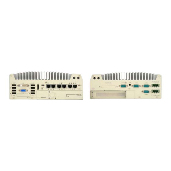
Page 40: Front Panel I/O
NOTE For demonstration purposes, Nuvo-9000E/ P will be used in most illustrations. A dedicated illustration will be shown if the component is significantly different. The Nuvo-9000 series systems’ front panel features the following external I/O connections. Nuvo-9000DE/ E/ P series... - Page 41 Nuvo-9000 Series reset button DVI-D output supports resolution up to 1920 x 1200@60Hz and is DVI port compatible with other digital connections via an adapter. VGA port VGA output supports resolution up to 1920 x 1200@60Hz USB3.1 Gen1x1 USB3.1 Gen 1 offers up to 5Gbps of data-throughput performance port Support display resolutions up to 4096 x 2304 @ 60Hz.
-
Page 42: Usb3.2 Gen2X1 Port
Nuvo-9000 Series 2.2.1 USB3.2 Gen2x1 Port The system’s USB 3.2 Gen2x1 ports (10Gbps) are implemented via native xHCI (eXtensible Host Controller Interface) controller and are backward compatible with USB3.2 Gen.1 USB 2.0, USB 1.1 and USB 1.0 devices. UFEI USB is also supported so you can use USB keyboard/ mouse in UEFI shell environment. -
Page 43: Cmos Reset Button
Nuvo-9000 Series 2.2.3 CMOS Reset Button The CMOS Reset button is used to manually reset the motherboard BIOS in case of system halt or malfunction. To avoid unexpected operation, it is purposely placed behind the panel. To reset, disconnect the DC power input, and use the tip of a pen to press and hold for at least 5 seconds to reset the BIOS. -
Page 44: Dvi Port
Nuvo-9000 Series 2.2.4 DVI Port DVI-D transmits graphics data in digital format and therefore can deliver better image quality at high resolution. The DVI connector on the front panel can either output DVI signals or other digital signals (via an adapter/ cable) depending on the display device connected. It supports resolutions up to 1920x1200@60Hz. -
Page 45: Vga Port
Nuvo-9000 Series 2.2.5 VGA Port VGA connector is the most common video display connection. The VGA output supports up to 1920x1200@60Hz resolution. The system supports triple independent display outputs by connecting display devices to VGA, DVI and DisplayPort connection. To support multiple display outputs and achieve best VGA output resolution in Windows, you need to install corresponding graphics drivers. -
Page 46: Usb3.2 Gen 1X1 Port
Nuvo-9000 Series 2.2.6 USB3.2 Gen 1x1 Port The system’s USB 3.2 Gen1x1 ports (5Gbps) are implemented via native xHCI (eXtensible Host Controller Interface) controller and are backward compatible with USB 2.0, USB 1.1 and USB 1.0 devices. UEFI USB is also supported so you can use USB keyboard/mouse in UEFI shell environment. -
Page 47: Displayport
Nuvo-9000 Series 2.2.7 DisplayPort The system has a DisplayPort (DP) output which is a digital display interface that mainly connect video source and carry audio to a display device. When connecting a DP, it can deliver up to 4K UHD (4096 x 2304 @ 60Hz) in resolution. The system is designed to support passive DP adapter/ cable. -
Page 48: Usb3.2 Gen2X2 Type-C Port
Nuvo-9000 Series 2.2.8 USB3.2 Gen2x2 Type-C Port The system’s USB 3.2 Gen2x2 type-C port offers up to 20Gbps of data transfer bandwidth, and is implemented via the native xHCI (eXtensible Host Controller Interface) controller. The port is backward compatible with USB3.2 Gen.1 USB 2.0, USB 1.1 and USB 1.0 devices via a USB hub (not included) to connect to external devices. -
Page 49: Ethernet Port/ Optional Poe
Nuvo-9000 Series 2.2.9 2.5 Ethernet Port/ Optional PoE+ All Nuvo-9000 series systems offer one 2.5GbE port (in black) and one GbE port (in blue) while Nuvo-9006E/ P/ DE systems have four additional 2.5GbE (with optional Power over Ethernet) ports marked in green on the front panel. -
Page 50: 2.2.10 Reset Button
Nuvo-9000 Series 2.2.10 Reset Button The reset button is used to manually reset the system in case of system halt or malfunction. To avoid unexpected reset, the button is purposely placed behind the panel. To reset, please use a pin-like object (eg. tip of a pen) to access the reset button 2.2.11 LED Indicators... -
Page 51: 2.2.12 Power Button
Nuvo-9000 Series 2.2.12 Power Button The power button is a non-latched switch for ATX mode on/off operation. To turn on the system, press the power button and the PWR LED should light-up green. To turn off the system, issuing a shutdown command in OS is preferred, or you can simply press the power button. To force shutdown when the system freezes, press and hold the power button for 5 seconds. -
Page 52: 2.2.14 Cassette Module
Nuvo-9000 Series 2.2.14 Cassette Module (R.O.C. Patent No. M456527) Neousys’ patented expansion Cassette provides a separated compartment to accommodate an add-on card. It effectively manages thermal conditions of both the system and the add-on card. The modular concept brought by Cassette module also reduces the complexity of installing and replacing an add-on card in the fanless controller. -
Page 53: Rear Panel I/O
Nuvo-9000 Series Rear Panel I/O The Nuvo-9000 rear panel features MezIO port, four (4) COM ports, 3-pin terminal and 3-pin on/ off control. The Cassette module can be located at the bottom of the enclosure. The connectors of the installed PCI or PCIe card within the Cassette module can be accessed from this side of the panel. -
Page 54: 4-Pole 3.5Mm Headphone/ Microphone Jack
The system audio function uses high definition audio. There is a female 4-pole audio jack for headphone (speaker) output and microphone input. The HD audio codec is natively supported in Windows 10 and Windows 11, and no additional drivers are required to enable the audio function on Nuvo-9000 series. -
Page 55: Com Ports
Nuvo-9000 Series 2.3.2 COM Ports The system provides four COM ports for communicating with external devices. These COM ports are implemented using industrial-grade ITE8786 Super IO chip (-40 to 85°C) and provide up to 115200 bps baud rate. COM1 and COM2 (in red) are software-configurable RS-232/ 422/ 485 ports. COM3 and COM4 (in blue) are standard 9-wire RS-232 ports. -
Page 56: 3-Pin Terminal Block For Dc And Ignition Input
Nuvo-9000 Series 2.3.3 3-Pin Terminal Block for DC and Ignition Input The system accepts a wide range of DC power input from 8 to 48V via a 3-pin pluggable terminal block, which is fit for field usage where DC power is usually provided. The screw clamping mechanism on the terminal block offers connection reliability when wiring DC power. -
Page 57: Internal I/O Functions
Nuvo-9000 Series Internal I/O Functions In addition to I/O connectors on the front panel, the system also provides internal on-board connectors, such as remote on/off control, LED status output, internal USB 2.0 ports, etc. In this section, we’ll illustrate these internal I/O functions. -
Page 58: Mini-Pcie Socket & Pin Definition
Nuvo-9000 Series 2.4.2 mini-PCIe Socket & Pin Definition The system provides a mini-PCIe socket (indicated in blue) that is in compliance with mini-PCIe specification rev. 1.2. This mini-PCIe socket is designed with SIM card (slot indicated in red) support. With a SIM card installed, your system can access the internet via your network provider’s 4G/ 3G network. - Page 59 Nuvo-9000 Series mini-PCIe socket definition Signal (mPCIe) Pin # Signal (mPCIe) WAKE# +3.3Vaux +1.5V CLKREQ# UIM_PWR UIM_DATA REFCLK- UIM_CLK REFCLK+ UIM_RESET UIM_VPP Mechanical Key Reserved* (UIM_C8) Reserved* (UIM_C4) W_DISABLE# PERST# PERn0 3.3V PERp0 +1.5V SMB_CLK PETn0 SMB_DATA PETp0 USB_D- USB_D+ 3.3V...
-
Page 60: 2242/ 3052 (B Key), Mini-Sim Card Slot & Pin Definition
Nuvo-9000 Series 2.4.3 M.2 2242/ 3052 (B Key), Mini-SIM Card Slot & Pin Definition The system has an M.2 2242/ 3052 slot (indicated in blue rectangle) with a 5G/ 4G SIM slot (indicated in rectangle). A copper standoff is provided for you to secure onto the... - Page 61 Nuvo-9000 Series M.2 (B Key) Slot Pin Definition Pin # Signal Pin # Signal +3V3 +3V3 FULL_CARD_POWER_OFF_N USB_D+ W_DISABLE_N USB_D- Mechanical Key USB3.0-RX- USB3.0-RX+ UIM1-RESET UIM1-CLK USB3.0-TX- UIM1-DATA USB3.0-TX+ UIM1-PWR PERn0 / SATA-B+ UIM2-DET PERp0 / SATA-B- UIM2-DATA UIM2-CLK PETn0 / SATA-A-...
-
Page 62: Sata Ports
(indicated in blue) features a 7-pin SATA connector. However, due to mechanical restrictions, only two SATA ports can be accommodated inside the Nuvo-9000 series. The two power connectors (indicated in red) can accommodate a 2.5” HDD/ SSD each in the internal HDD bracket. -
Page 63: Dip Switch
Nuvo-9000 Series 2.4.5 DIP Switch The DIP switch (indicated in blue) should be already configured out of the factory. Users need only set the 4th DIP switch to ON for BIOS update and switch it back to the OFF position when BIOS upgrade has completed. -
Page 64: On/ Off Ctrl & Status Output
Nuvo-9000 Series 2.4.6 On/ Off Ctrl & Status Output Pin# Definition Description WDT_LED- [Output] Watchdog timer indicator, flashing when Watchdog WDT_LED+ timer is active Standby Power- [Output] Standby power indicator, on if DC power is applied and system is in S5 (standby) mode. -
Page 65: Internal Usb 2.0 Port
Nuvo-9000 Series 2.4.7 Internal USB 2.0 Port The system’s motherboard has an internal USB2.0 port on the PCBA. You can utilize this USB port to connect a USB protection dongle inside the chassis of the system. -
Page 66: 2280 (M Key) Slot For Nvme Ssd
Nuvo-9000 Series 2.4.8 M.2 2280 (M Key) Slot for NVMe SSD The system has a Gen4 x4 PCIe M.2 2280 slot for you to install an NVMe SSD. The M.2 NVMe SSD offers significantly better system performances when compared to a 2.5” SSD. - Page 67 Nuvo-9000 Series M.2 (M Key) Slot Pin Definition Pin # Signal Pin # Signal +3V3 +3V3 PERN3 PERP3 DAS/DSS_N PETN3 +3V3 PETP3 +3V3 +3V3 PERN2 +3V3 PERP2 PETN2 PETP2 PERN1 PERP1 PETN1 PETP1 PERn0 PERp0 PETn0 PETp0 PERST_N REFCLKN REFCLKP...
-
Page 68: Mezio Tm Interface & Pin Definition
Nuvo-9000 Series 2.4.9 MezIO Interface & Pin Definition MezIO is an innovative interface designed for integrating application-oriented I/O functions into an embedded system. It offers computer signals, power rails and control signals via a high-speed connector. MezIO is also mechanically reliable benefited from its 3-point mounted mezzanine structure. - Page 69 Nuvo-9000 Series MezIO Interface Pin Definition MezIO interface leverages FCI BergStak® board-to-board connector to provide interconnectivity of high-speed signals. The receptacle part on the PCBA is FCI 61082-063402LF while the plug part on the MezIO module is FCI 61083-064402LF. Please refer to the following table for signal definition of its 60-pin connector.
-
Page 70: System Installation
Nuvo-9000 Series System Installation Before disassembling the system enclosure and installing components and modules, please make sure you have done the following: It is recommended that only qualified service personnel should install and service this product to avoid injury or damage to the system. -
Page 71: Disassembling The System
Nuvo-9000 Series Disassembling the System To access system internal components, the system needs to be disassembled. To disassemble the system enclosure, you need to remove the Cassette module and screws on both I/O panels. Turn the system upside-down and remove the four screws (indicated in blue) at the bottom of the Cassette module. - Page 72 Nuvo-9000 Series NOTE For Nuvo-9000E/ P/ DE series systems only.
- Page 73 Nuvo-9000 Series Nuvo-9000E/ P/ DE systems Nuvo-900LP systems Remove the front I/O panel.
- Page 74 Nuvo-9000 Series Nuvo-9000E/ P/ DE systems On the rear I/O panel, remove the hexa-screws indicated below. Nuvo-9000E/ P/ DE systems Nuvo-9000LP systems Remove the rear I/O panel.
- Page 75 Nuvo-9000 Series Gently lift the system’s bottom panel.
- Page 76 Nuvo-9000 Series Once the bottom panel has been removed, you should have access to the system’s internal I/O interfaces.
-
Page 77: Installing Internal Components
Nuvo-9000 Series Installing Internal Components NOTE For demonstration purposes, Nuvo-9000E/ P will be used in most illustrations. A dedicated illustration will be shown if the component is significantly different. 3.2.1 CPU Installation for Barebone System To install the CPU, you will need to separate the heatsink and the motherboard. - Page 78 Nuvo-9000 Series Gently separate the motherboard from the heatsink, you’ll see the CPU socket protective cover, place finger tips underneath the sign “REMOVE” for leverage and gently lift the cover. CPU protective cover WARNING With the protective cover removed, please be careful when handling the motherboard. DO...
- Page 79 Nuvo-9000 Series Remove the CPU from its container/ tray. Match the four notches on the side (indicated by blue arrows) to the protrusions in the socket, gently lower the CPU into the socket. Pay attention to the seating orientation, notice there is a short side (indicated by...
- Page 80 Nuvo-9000 Series Turn the motherboard around while holding the CPU retention bracket in-place, and secure the bracket by tightening two M3 P-head screws on the other side of the motherboard. Hold CPU bracket firmly and turn Secure two M3 P-head screws the motherboard around Remove all thermal pads’...
- Page 81 Nuvo-9000 Series With the four motherboard standoffs aligned, gently lower the motherboard onto the heatsink and secure the four screws. Please remember to remove the protective film (indicated in red) on the CPU’s thermal pad as well. Four standoffs on the heatsink...
- Page 82 Nuvo-9000 Series Once the motherboard has been installed, you’re ready to secure the four screws that help the heatsink apply pressure to the CPU/ chipset die. You’ll want to apply even pressure to the corners by gradually tightening each screw. Please refer to the recommended order when tightening the screws.
-
Page 83: Remove And Replace The Existing Cpu
Nuvo-9000 Series 3.2.2 Remove and Replace the Existing CPU To replace the existing CPU, you will need to separate the heatsink and the motherboard. To do so, remove the eight screws indicated below. - Page 84 Nuvo-9000 Series Remove the screws indicated once you separate the heatsink from the motherboard to remove the CPU holder.
- Page 85 Nuvo-9000 Series At this point, the CPU and retention bracket may be stuck onto the heatsink (due to the thermal pad). Please use a plastic pry tool and gentle separate the CPU/ holder from the heatsink. WARNING With the heatsink, CPU, and retention bracket removed, please be careful when handling the motherboard.
- Page 86 Nuvo-9000 Series Place a new CPU thermal pad (indicated in blue) onto the motherboard for the new CPU.
- Page 87 Nuvo-9000 Series Remove and clean off any thermal pad residues around the socket/ motherboard. Gently place the new CPU into the socket by matching the four notches (indicated by blues arrows) on the side to the protrusions in the socket. Pay attention to the seating...
- Page 88 Nuvo-9000 Series Turn the motherboard around and secure the bracket by tightening two M3 P-head screws.
- Page 89 Nuvo-9000 Series 11. Once the motherboard has been installed, you’re ready to secure the four screws that help the heatsink apply pressure to the CPU/ chipset die. You’ll want to apply even pressure to the corners by gradually tightening each screw. Please refer to the recommended order when tightening the screws.
-
Page 90: Ddr5 So-Dimm Installation
Nuvo-9000 Series 3.2.3 DDR5 SO-DIMM Installation There are two SO-DIMM memory slots (indicated in blue) on the motherboard that supports a total maximum of 64GB DDR5-4800. Please follow the procedures below to replace or install the memory modules. 1. Please refer to the section “Disassembling the... - Page 91 Nuvo-9000 Series 4. Push the memory module down until it is clipped-in. 5. Repeat steps 3 and 4 to install the other module. 6. Before you reinstall the system enclosure, please remove the respective thermal pad protective film located on the enclosure’s bottom panel.
-
Page 92: Mpcie Module, Mini-Sim (2Ff) Card And Antenna Installation
Nuvo-9000 Series 3.2.4 mPCIe Module, Mini-SIM (2FF) Card and Antenna Installation The system has an mPCIe slot (indicated in blue) coupled with Mini-SIM socket (indicated in red)for installing 3G/ 4G module. For installation, please refer to the following instructions. Please refer to the section “Disassembling the... - Page 93 Nuvo-9000 Series Secure the Mini-SIM card by sliding the holder. Insert the mPCIe module on a 45 degree angle into the mPCIe slot and secure the module. Insert on 45 degree angle Secure the module Clip on the IPEZ-to-SMA cable to the module and secure the antenna to the front or rear panel.
-
Page 94: 2242/ 3052 (B Key) Module And Micro-Sim (3Ff) Card Installation
Nuvo-9000 Series 3.2.5 M.2 2242/ 3052 (B Key) Module and Micro-SIM (3FF) Card Installation The system has an M.2 slot (indicated in blue rectangle) for installing 5G/ 4G with a micro-SIM card or a WiFi module card slots (indicated in rectangle).For installation, please refer to the... - Page 95 Nuvo-9000 Series Insert the module on a 45 degree angle. Gently press down and secure the module with an M2.5 P-head screw. Clip on the IPEZ-to-SMA cable to the module and secure the antenna to the front or rear panel. Please refer to the module’s manual for clip-on connection.
-
Page 96: 2280 Nvme Ssd Installation
Nuvo-9000 Series 3.2.6 M.2 2280 NVMe SSD Installation The system has a Gen4 x4 PCIe M.2 2280 slot for you to install an NVMe SSD. For installation, please refer to the following instructions. Please refer to the section “Disassembling the System”, you may not need to completely... - Page 97 Nuvo-9000 Series Gently press down and secure the module with an M2.5 P-head screw. Remove the thermal pad’s protective film at the bottom of the enclosure panel for the NVMe module. Reinstall the system enclosure and panel when done. If you need to install other components, please refer to respective sections.
-
Page 98: Mezio Tm Module Installation
Nuvo-9000 Series 3.2.7 MezIO Module Installation MezIO is an innovative interface designed for integrating application-oriented I/O functions into an embedded system. It offers computer signals, power rails and control signals via a high-speed connector. MezIO is also mechanically reliable benefited from its 3-point mounted mezzanine structure. - Page 99 Nuvo-9000 Series The MezIO module is secured by the three stand-mounts indicated in the illustration below. Gently lower the MezIO module onto the three stand-mounts while matching the MezIO interface. Secure the module using three screws supplied. Reinstall the system enclosure and panel when done.
-
Page 100: Hdd/ Ssd Installation
Nuvo-9000 Series 3.2.8 HDD/ SSD Installation NOTE Supports up to 15mm thickness HDD/ SSD. The system has two SATA ports (indicated in blue) and two four pin power connectors (indicated in red). The SATA and power cables should already be connected on the motherboard so users only need to install the HDD/ SSD. - Page 101 Nuvo-9000 Series Turn the system upside-down and remove the three screws indicated in the illustration below and lift the tray out of the system. Take the HDD/ SSD thermal pad (if not already attached) out of the accessory box and place it in the middle of the tray.
- Page 102 Nuvo-9000 Series Place the HDD/ SSD (with labels facing up) and match the SATA connector end to the side with two screw holes (indicated in blue), secure the HDD/ SSD with the supplied flathead screws (4 per drive). Connect the 22-pin SATA cable to the installed HDD/ SSD.
-
Page 103: Hot-Swappable Tray Hdd/Ssd Installation (Nuvo-9000Lp Only)
Nuvo-9000 Series 3.2.9 2.5” Hot-swappable Tray HDD/SSD Installation (Nuvo-9000LP Only) The system features a 2.5” external hot-swappable HDD/ SSD slot (indicated in blue), and secured by a lock (indicated in red). It coincides with the internal drive and can be configured into RAID 0 or 1 storage. -
Page 104: Ethernet/ Poe+ Port Panel Screw Fix
Nuvo-9000 Series 3.2.10 Ethernet/ PoE+ Port Panel Screw Fix The system's RJ45 Ethernet ports have panel screw fix holes (indicated in blue circles) to secure the cable connection. To install and make use to the panel screw fix connection, you must acquire panel screw fix cables such as the cable shown below. -
Page 105: Pcie/ Pci Card Installation Into Cassette Module (Nuvo-9000E/ P/ De Only)
Nuvo-9000 Series 3.2.11 PCIe/ PCI Card Installation into Cassette Module (Nuvo-9000E/ P/ DE Only) NOTE Nuvo-9000E/ P and Nuvo-9000DE systems’ Cassette module share the exact same screw locations and removal procedure, therefore a Nuvo-9000E/ P will be used for demonstration. - Page 106 Nuvo-9000 Series Gently wiggle the Cassette module and separate it from the system enclosure. Remove the screw to open the Cassette cover.
- Page 107 Nuvo-9000 Series Before installing the PCI/ PCIe card into the Cassette module, it is recommended to attach the rubber spacers provided onto the back of the card to avoid possible contact with the enclosure. Simply attach the rubber spacers on the back of the card, in the four corners.
- Page 108 Nuvo-9000 Series Remove the bezel cover (indicated in blue circle) and insert the card into the PCIe/ PCI slot while making sure the bezel is properly inserted into the notch and the card is secured in place with screw. NOTE Repeat the procedure for installing a second card into a Nuvo-9000DE series system.
- Page 109 Nuvo-9000 Series Secure the screw indicated. Gently lower the Cassette module back onto the system enclosure and secure the module onto the system enclosure by securing the following screws.
-
Page 110: Installing The System Enclosure
Nuvo-9000 Series Installing the System Enclosure To reinstall the system enclosure, place the bottom panel on top of the motherboard while making sure both sides are inserted into the heatsink (indicated in blue). - Page 111 Nuvo-9000 Series Install the front panel and secure screws indicated in blue. Nuvo-9000E/ P/ DE systems Nuvo-900LP systems...
- Page 112 Nuvo-9000 Series Install the rear panel and secure screws indicated in blue. Nuvo-9000E/ P/ DE systems Nuvo-9000LP systems...
- Page 113 Nuvo-9000 Series Install the Cassette module and secure screws indicated in blue. NOTE Not applicable to Nuvo-9000LP systems. Install the Cassette module Secure the screws indicated...
-
Page 114: Wall Mount Bracket/ Din-Rail Installation
Nuvo-9000 Series Wall Mount Bracket/ DIN-rail Installation Nuvo-9000 series ships with dedicated wall mount and DIN-rail (optional). NOTE You will need to remove the four (4) rubber stands at the bottom of the enclosure if they have been attached. 3.4.1 Wall Mount Bracket Installation To install the system as a wall mount device, please refer to the following instructions. - Page 115 Nuvo-9000 Series When wall mounting, place the heatsink fins perpendicular to the ground for better heat dissipation efficiency.
-
Page 116: Din-Rail Installation (Optional)
Nuvo-9000 Series 3.4.2 DIN-rail Installation (Optional) The system also has an optional DIN-rail mounting kit. The kit includes a bracket (in blue) and a DIN-rail mounting clip (in red). By fixing the clip to the bracket using four M4 flat-head screws and fixing the bracket assembly to the system four M4 screws (in green), complete the installation by clipping the system onto the DIN rail. -
Page 117: Powering On The System
Nuvo-9000 Series Powering On the System There are three methods to power on the system Pressing the power button Using an external non-latched switch by connecting to the remote on/ off plug Sending a LAN packet via Ethernet (Wake-on-LAN) 3.5.1... -
Page 118: Powering On Using External Non-Latched Switch
Nuvo-9000 Series 3.5.2 Powering On Using External Non-latched Switch If your application demands the system to be placed inside a cabinet, you may use an external non-latched switch to power on/ off the system. The system provides a 3-pin “Remote On/ Off”... -
Page 119: Powering On Using Wake-On-Lan
Nuvo-9000 Series 3.5.3 Powering On Using Wake-on-LAN Wake-on-LAN (WOL) is a mechanism to wake up a computer system from a S5 (system off with standby power) state via issuing a magic packet. The system’s Wake-on-LAN compatible GbE port is shown below. - Page 120 Nuvo-9000 Series “Network>Properties>Change adapter settings”. Locate and double-click on the adapter Intel® I219 Gigabit Network Connection, click on Configure... Click on the Power Management tab and check the following options. Click on OK when done. Magic Packet The magic packet is a broadcast frame containing anywhere within its payload 6 bytes of all 255 (FF FFFFFFFFFF in hexadecimal), followed by sixteen repetitions of the target computer's 48-bit MAC address.
- Page 121 Nuvo-9000 Series There are some free tools available on Internet that can be used to send a magic packet. Please refer to the following link to understand more about Magic Packet.
-
Page 122: System Configuration
Nuvo-9000 Series System Configuration BIOS Settings The system is shipped with factory-default BIOS settings meticulously programmed for optimum performance and compatibility. In this section, we’ll illustrate some of BIOS settings you may need to modify. Please always make sure you understand the effect of change before you proceed with any modification. -
Page 123: Com Port Configuration
Nuvo-9000 Series 4.1.1 COM Port Configuration The system’s COM1/ COM2 ports support RS-232 (full-duplex), RS-422 (full-duplex) and RS-485 (half-duplex) mode. You can set the COM1 operating mode via BIOS settings. Another option in BIOS called “Slew Rate” defines how sharp the rising/falling edge is for the output signal of COM1. -
Page 124: Com Port High Speed Mode
Nuvo-9000 Series 4.1.2 COM Port High Speed Mode The high speed mode of each COM port effectively allows for the port's baud rate generator to operate at 8x the speed with an effective baud rate of 921,600 bps (115,200 x 8). Please refer to the following instructions on how to enable the high speed mode for your COM port (COM1 used as an example). -
Page 125: Delay For Peg Initialization
Nuvo-9000 Series 4.1.3 Delay for PEG Initialization This setting offers delay in milliseconds for PEG port initialization and PCI enumeration. By increasing the delay value, it may eliminate compatibility issue(s) with some PCIe add-on cards. To set PEG delay in milliseconds: 1. -
Page 126: Volume Management Device (Vmd)
Nuvo-9000 Series 4.1.4 Volume Management Device (VMD) To set up a RAID 0 or 1 volume, you need to have at least two hard drives or SSDs installed. The system supports RAID configurations in RAID 0 (striping) or RAID 1 (mirror) mode. Users can select the configuration that best suit their needs with RAID 0 (striping) mode offering better hard drive read/ write performances while RAID 1 (mirror) offers better data security. - Page 127 Nuvo-9000 Series Highlight [Enable VMD controller], press ENTER to bring up Options, Enabled/ Disabled, select Enabled and press ENTER.
- Page 128 Nuvo-9000 Series Highlight [RAID0] or [RAID1], press ENTER to bring up options, Enabled/ Disabled, select your choice and press ENTER again to confirm selection. Highlight your selection, press Enter and press F10 to “Exit Saving Changes”.
-
Page 129: Tpm Availability
Nuvo-9000 Series 4.1.5 TPM Availability Trusted Platform Module (TPM) is a hardware-based cryptoprocessor to secure hardware by integrating cryptographic keys into devices. The system is designed with on-board TPM 2.0 module. As TPM 2.0 requires 64-bit Windows 10 with UEFI boot mode, it is enabled in BIOS by default. -
Page 130: Power Over Ethernet (Poe) Power Enable
Nuvo-9000 Series 4.1.6 Power over Ethernet (PoE) Power Enable Power over Ethernet (PoE) supplies electrical power and data on a standard CAT-5/CAT-6 Ethernet cable. Acting as a PoE PSE (Power Sourcing Equipment), compliant with IEEE 802.3at, each PoE port delivers up to 25W to a Powered Device (PD). The system has a total 100W power budget. - Page 131 You can also enable/ disable each port, individually. Simply use the arrow key to highlight the port, press ENTER to bring up options (Enabled/ Disabled), press ENTER again to select the option. Nuvo-9000 series LAN ports Press F10 to “Exit Saving Changes.
-
Page 132: Auto Wake On S5
Nuvo-9000 Series 4.1.7 Auto Wake on S5 When the system is set to operate in S5 state, the user can specify a time to turn on the system, daily or monthly. Value Option Description Auto Wake on S5 Disabled The system does not turn on when operating in state S5. -
Page 133: Power On After Power Failure Option
Nuvo-9000 Series 4.1.8 Power On After Power Failure Option This option defines the behavior of System series when DC power is supplied. Value Description S0 – Power On System is powered on when DC power is supplied. S5 – Power Off System is kept in off state when DC power is supplied. -
Page 134: Power & Performance (Cpu Sku Power Configuration)
Nuvo-9000 Series 4.1.9 Power & Performance (CPU SKU Power Configuration) The system supports Intel 12 Gen Alder Lake LGA 1700 CPUs from 35W to 65W TDP. A unique feature, “SKU Power Config” is implemented in BIOS to allow users to specific user-defined SKU power limit. -
Page 135: 4.1.10 Wake On Lan Option
Nuvo-9000 Series 4.1.10 Wake on LAN Option Wake-on-LAN (WOL) is a mechanism which allows you to turn on your System series via the Ethernet connection. To utilize Wake-on-LAN function, you have to enable this option first in BIOS settings. Please refer “Powering On Using... -
Page 136: 4.1.11 Boot Menu
Nuvo-9000 Series 4.1.11 Boot Menu The Boot menu in BIOS allows you to specify the system’s boot characteristics by setting bootable device components (boot media) and method. Or, you may press F12 upon system start up and select a device you wish boot from. - Page 137 Nuvo-9000 Series boot via I219 Only/ I225 Only or All NICs. Add Boot Options First Newly detected boot media are placed at the top of the boot order. Last Newly detected boot media are placed at the bottom of the boot order.
-
Page 138: Add Boot Options (Position New Boot Device)
Nuvo-9000 Series 4.1.12 Add Boot Options (Position New Boot Device) The “Add Boot Options” allow you to determine whether a newly added device (eg. USB flash disk) is to boot as the first device to boot or the last in the boot sequence. -
Page 139: 4.1.13 Watchdog Timer For Booting
Nuvo-9000 Series 4.1.13 Watchdog Timer for Booting The watchdog timer secures the boot process by means of a timer. Once the timer expires, a reset command is issued to initiate another booting process. There are two options in BIOS menu, “Automatically after POST” and “Manually after Entering OS”. When “Automatically after POST”... -
Page 140: Amt Configuration
Nuvo-9000 Series AMT Configuration Intel® AMT (Active Management Technology) is a hardware-based technology for remotely managing target PCs via Ethernet connection. The system supports AMT function via its Ethernet port implemented with Intel I219-LM. Prior to using the AMT function to remotely control the system, you need to configure AMT password and network settings. - Page 141 Nuvo-9000 Series When entering MEBx for the first time, it will ask for the default (old) password. Please type “admin” and press ENTER. The system will then request that you enter a new password. The new password must consists of at least one 7-bit ASCII non alpha-numeric character, above 32 (eg,!, @, $) and 8 to 32 characters long.
-
Page 142: Raid Configuration
Nuvo-9000 Series RAID Configuration To set up a RAID 0 or 1 volume, you need to have at least two hard drives or SSDs installed. The system supports RAID configurations in RAID 0 (striping) or RAID 1 (mirror) mode. Users can select the configuration that best suit their needs with RAID 0 (striping) mode offering better hard drive read/ write performances while RAID 1 (mirror) offers better data security. - Page 143 Nuvo-9000 Series 3. Select [Enable VMD controller] and press ENTER, highlight [Enabled] and press ENTER. 4. Press F10 to “Exit Saving Changes” and reboot the system. 5. When the system reboots, press [F3] to enter the Device Manager configuration utility.
-
Page 144: Raid Volume Setup
Nuvo-9000 Series 4.3.2 RAID Volume Setup Once you’ve press F3 upon system boot up and you are in the Device Manager configuration utility, select [Intel® Rapid Storage Technology] and press ENTER. The following screen shows Non-RAID physical disks and the option “Create RAID Volume”. - Page 145 Nuvo-9000 Series The Name option allows you to name your RAID volume. Press ENTER when ready to go to the next option.
- Page 146 Nuvo-9000 Series The RAID Level option allows you to select RAID-0 (stripping) or RAID-1 (mirror) for your RAID volume. Press ENTER when ready.
- Page 147 Nuvo-9000 Series The Select Disks option allows you to select disk drives for your RAID volume. Highlight a drive and press ENTER, use up/ down arrow keys to highlight “x” and press ENTER to confirm the selection. A minimum of two disk drives must be selected for RAID-0 or RAID-1...
- Page 148 Nuvo-9000 Series The Stripe Size option allows you to configure the stripe size of your RAID volume. Available stripe sizes are 4KB, 8KB, 16KB, 32KB, 64KB, 128KB, use the up and down arrow keys to highlight and press ENTER to confirm the stripe size selection.
- Page 149 Nuvo-9000 Series The Capacity (MB) option allows you to configure the storage capacity of your RAID volume. By default, the full storage capacity will be applied. Once you have entered a capacity, press ENTER to confirm. The Create Volume option is the final step in the volume creation process. Highlight “Create Volume”...
- Page 150 Nuvo-9000 Series A summary and status of the RAID volume will be shown when the RAID volume is successfully created. 10. Press F10 to save and Esc to exit the Intel® Rapid Storage Technology configuration page. NOTE The above process was to create a RAID-0 volume. If you wish to create a RAID-1 volume,...
-
Page 151: Loading Raid Driver For Windows Installation
Nuvo-9000 Series 4.3.3 Loading RAID Driver for Windows Installation To install Windows on the RAID volume you created, please refer to the following procedure: Please prepare a bootable Windows installation USB drive with the zip file “f6vmdflpy-x64”. Download and unzip the driver files, copy the driver files onto the Windows installation USB drive. - Page 152 Nuvo-9000 Series In the pop-up Window, select “Browse”, go to the directory where you saved the unzipped drivers “f6vmdflpy-x64”, and click OK.
- Page 153 Nuvo-9000 Series Select the driver “Intel RST VMD Controller 467F” and click on Next. The previous created RAID volume shall appear as unallocated space. From here, just follow the standard Windows installation procedures.
-
Page 154: Os Support And Driver Installation
OS Support and Driver Installation Operating System Compatibility The system supports most operating system developed for Intel® x86 architecture. The following list contains the operating systems which have been tested by Neousys Technology. Microsoft Window 10 Professional (x64) ... -
Page 155: System Driver Installation
Nuvo-9000 Series System Driver Installation The system drivers are available online, please click on this link to download the drivers. Driver Installation for Watchdog Timer Control Neousys provides a driver package which contain function APIs for Watchdog Timer control function. You should install the driver package (WDT_DIO_Setup.exe) in prior to use these functions. -
Page 156: Appendix A Using Wdt & Dio
In this section, we’ll illustrate how to use the function library provided by Neousys to program the WDT functions. Currently, WDT driver library supports Windows 10 x64 and WOW64 platform. For other OS support, please contact Neousys Technology for further information. Installing WDT_DIO Library The WDT_DIO function library is delivered in the form of a setup package named WDT_DIO_Setup.exe. -
Page 157: Wdt And Dio Library Installation
Nuvo-9000 Series WDT and DIO Library Installation To setup WDT & DIO Library, please follow instructions below. 1. Execute WDT_DIO_Setup.2.3.2.0.exe (or later) and the following dialog appears. 2. Click “Next >” and specify the directory of installing related files. The default directory is... - Page 158 Nuvo-9000 Series 3. Once the installation has finished, a dialog will appear to prompt you to reboot the system. The WDT & DIO library will take effect after the system has rebooted. 4. When programming your WDT or DIO program, the related files are located in...
-
Page 159: Wdt Functions
Nuvo-9000 Series WDT Functions InitWDT BOOL InitWDT(void); Syntax Description: Initialize the WDT function. You should always invoke InitWDT() before set or start watchdog timer. Parameter None Return Value TRUE: Successfully initialized FALSE: Failed to initialize BOOL bRet = InitWDT() Usage... -
Page 160: Startwdt
Nuvo-9000 Series StartWDT Syntax BOOL StartWDT(void); Starts WDT countdown. Once started, the WDT LED indicator Description will begin blinking. If ResetWDT() or StopWDT is not invoked before WDT countdowns to 0, the WDT expires and the system resets. Parameter None... -
Page 161: Appendix B Poe On/ Off Control
Nuvo-9000 Series Appendix B PoE On/ Off Control Nuvo-9000series offer 802.3at PoE+ ports and users are allowed to manually turn on or off the power supply of each PoE port. This can be useful in power device (PD) fault-recovery or power reset. -
Page 162: Enablepoeport
Nuvo-9000 Series EnablePoEPort Syntax BOOL EnablePoEPort (BYTE port); Turn on PoE power of designated PoE port. Description Parameter port BYTE value specifies the index of PoE port. Please refer to the following illustration, port should be a value of 1 ~ 4... -
Page 163: Disablepoeport
Nuvo-9000 Series DisablePoEPort Syntax BOOL DisablePoEPort (BYTE port); Turn off PoE power of designated PoE port Description Parameter port BYTE value specifies the index of PoE port. Please refer to the following illustration, port should be a value of 1 ~ 4...
Need help?
Do you have a question about the Nuvo-9000 Series and is the answer not in the manual?
Questions and answers