Table of Contents
Advertisement
Quick Links
Advertisement
Table of Contents

Subscribe to Our Youtube Channel
Related Manuals for Neousys Technology POC-351VTC


Summary of Contents for Neousys Technology POC-351VTC
- Page 1 Neousys Technology Inc. POC-351VTC User Manual Revision 1.0...
-
Page 2: Table Of Contents
Safety Precautions ......................... 8 Service and Maintenance ...................... 9 ESD Precautions ........................9 About This Manual ....................... 10 Introduction Specification of POC-351VTC .................. 12 Dimension ......................... 14 1.2.1 Front View ......................14 1.2.2 CAN and DIO Panel View ................. 15 1.2.3... - Page 3 Table of Content 3.2.1 DDR3L SO-DIMM Installation ................47 3.2.2 mini-PCIe Module, SIM Card and Antennae Installation ........49 3.2.3 mSATA Module Installation ................53 3.2.4 M.2 (2242/ 3042) Module Installation ..............55 3.2.5 MezIO Module Installation ................57 Installing the System Enclosure ................59 Wall Mount Bracket Installation (1) .................
- Page 4 Table of Content SetupDICOS ....................104 RegisterCallbackDICOS ................... 105 StartDICOS....................... 105 StopDICOS ....................... 106 DI COS Example ....................106...
-
Page 5: Legal Information
For questions in regards to hardware/ software compatibility, customers should contact Neousys Technology Inc. sales representative or technical support. To the extent permitted by applicable laws, Neousys Technology Inc. shall NOT be responsible for any interoperability or compatibility issues that may arise when (1) products, software, or options not certified and supported;... -
Page 6: Contact Information
Neousys Technology Inc. (Taipei, Taiwan) 15F, No.868-3, Zhongzheng Rd., Zhonghe Dist., New Taipei City, 23586, Taiwan Tel: +886-2-2223-6182 Fax: +886-2-2223-6183 Email, Website Americas Neousys Technology America Inc. 3384 Commercial Avenue, Northbrook, IL 60062, USA (Illinois, USA) Tel: +1-847-656-3298 Email, Website China Neousys Technology (China) Ltd. -
Page 7: Copyright Notice
This manual is intended to be used as an informative guide only and is subject to change without prior notice. It does not represent commitment from Neousys Technology Inc. Neousys Technology Inc. shall not be liable for any direct, indirect, special, incidental, or consequential damages arising from the use of the product or documentation, nor for any infringement on third party rights. -
Page 8: Safety Precautions
Safety Precautions Safety Precautions Read these instructions carefully before you install, operate, or transport the system. Install the system or DIN rail associated with, at a sturdy location Install the power socket outlet near the system where it is easily accessible ... -
Page 9: Service And Maintenance
Service and Maintenance/ ESD Precautions Service and Maintenance ONLY qualified personnel should service the system Shutdown the system, disconnect the power cord and all other connections before servicing the system When replacing/ installing additional components (expansion card, memory module, etc.), insert them as gently as possible while assuring proper connector engagement ESD Precautions... -
Page 10: About This Manual
About This Manual About This Manual This manual introduces and demonstrates installation procedures of Neousys POC-351VTC. Revision History Version Date Description Mar. 2018 Initial release... -
Page 11: Introduction
56 (W) x 153 (H) x 108 (D) mm. Designed for front panel I/O port access, POC-351VTC is easy to setup and is ideal for space limited in-vehicle installation such as railway, truck or bus applications. -
Page 12: Specification Of Poc-351Vtc
POC-351VTC Specification of POC-351VTC System Core Intel® Atom™ E3950 1.6/ 2.0GHz quad-core processor Processor Graphics Integrated Intel® HD Graphics 505 Memory 1x SODIMM socket for DDR3L-1866, up to 8GB Panel I/O Interface Ethernet 3x Gigabit Ethernet ports by Intel® I210 GbE controller IEEE 802.3at PoE+ on port #2 and #3... - Page 13 CE/ FCC Class A, according to EN 55022 & EN 55024 * The 100% CPU/GPU loading for high temperature test is applied using Passmark® BurnInTest™ v8.0. For detail testing criteria, please contact Neousys Technology ** For sub-zero operating temperature, a wide temperature HDD drive or Solid State Disk...
-
Page 14: Dimension
POC-351VTC Dimension 1.2.1 Front View... -
Page 15: Can And Dio Panel View
POC-351VTC 1.2.2 CAN and DIO Panel View... -
Page 16: Com And Audio Port Panel View
POC-351VTC 1.2.3 COM and Audio Port Panel View... -
Page 17: Bottom View
POC-351VTC 1.2.4 Bottom View... -
Page 18: Poc-351Vtc Mounting Options
POC-351VTC POC-351VTC Mounting Options The system comes with a wall mount bracket that allows the system to be mounted horizontally. As an option, a wall mount bracket that allows the system to be mounted vertically can be purchased. 1.3.1 Horizontal Wall Mount... -
Page 19: Vertical Wall Mount Bracket
POC-351VTC 1.3.2 Vertical Wall Mount Bracket... -
Page 20: Din Rail
POC-351VTC 1.3.3 DIN Rail... -
Page 21: System Overview
POC-351VTC System Overview Upon receiving and unpacking your POC-351VTC, please check immediately if the package contains all the items listed in the following table. If any item(s) are missing or damaged, please contact your local dealer or Neousys Technology. Unpacking the System... -
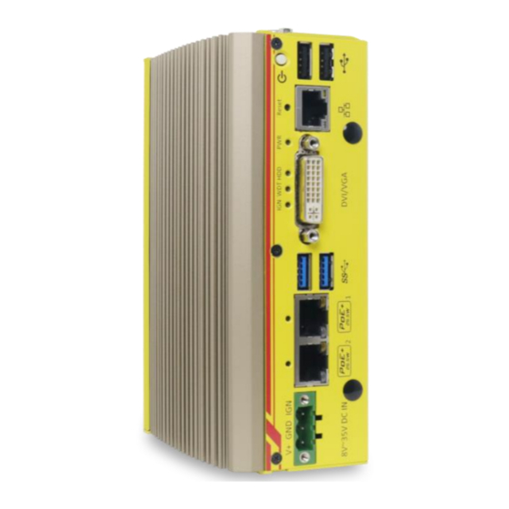
Page 22: Poc-351Vtc Front Panel
POC-351VTC POC-351VTC Front Panel The front panel of POC-351VTC feature rich I/O ports, it has three Gigabit Ethernet ports (Ports 2 and 3 are 802.3at Gigabit PoE+ ports), two USB3.0 ports, two USB2.0 ports, one DVI-I connector for VGA + DVI dual video output and 3-pin terminal block for DC input. -
Page 23: Usb 2.0 Port
1.0 devices. Legacy USB support is also provided so you can use USB keyboard/ mouse in DOS environment. xHCI driver is supported natively in Windows 10, therefore you do not need to install xHCI driver to utilize USB functions on POC-351VTC. 2.2.2 Power Button The power button is a non-latched switch for ATX mode on/off operation. -
Page 24: Reset Button
POC-351VTC 2.2.3 Reset Button The reset button is used to manually reset the system in case of system halt or malfunction. To avoid unexpected reset, the button is purposely placed behind the panel. To reset, please use a pin-like object (eg. tip of a pen) to access the reset button. -
Page 25: System Status Led
POC-351VTC 2.2.5 System Status LED There are four LED indicators on the front panel: PWR, HDD, WDT and IGN. The descriptions of these four LEDs are listed in the following table. Indicator Color Description Green Power indicator, lid when system is on... -
Page 26: Usb 3.0 Port
POC-351VTC 2.2.7 USB 3.0 Port The system offers two USB 3.0 (SuperSpeed USB) ports on its front panel. They are implemented by native xHCI (eXtensible Host Controller Interface) controller in Atom E3950 SoC and are backward compatible with USB 2.0, USB 1.1 and USB 1.0 devices. -
Page 27: 3-Pin Terminal Block For Dc Input/ Ignition Input
POC-351VTC 2.2.9 3-Pin Terminal Block for DC Input/ Ignition Input The system accepts a wi de range of DC power input from 8 to 35V via a 3-pin pluggable terminal block, which is fit for field usage where DC power is usually provided. -
Page 28: Com Port Panel
POC-351VTC COM Port Panel The top panel of POC-351VTC features additional I/O functions, such as 3.5mm speaker-out/ microphone-in jacks, COM ports implemented using ITE8786 SIO chip, and antenna holes for antenna installation. Item Description COM port 1 Software programmable RS-232/ 422/ 485 port... -
Page 29: Com Port (Com1)
POC-351VTC 2.3.1 COM Port (COM1) Implemented using industrial-grade ITE8786 Super IO chip (-40 to 85°C) and provide up to 921600 bps baud rate, COM1 is a software-configurable RS-232/422/485 port via 9-pin D-Sub male connector. The operation mode, slew rate and termination of COM1 can be set in BIOS setup utility. -
Page 30: Com Ports (Com2/ Com3/ Com4)
POC-351VTC 2.3.2 COM Ports (COM2/ COM3/ COM4) Implemented using industrial-grade ITE8786 Super IO chip (-40 to 85°C) and provide up to 921600 bps baud rate, the second D-Sub male connector (COM2/ 3/ 4) can be configured in BIOS as single RS-422/ 485 port (COM2) or three 3-wire RS-232 ports (COM2/COM3/COM4). -
Page 31: Mm Microphone-In/ Speaker-Out Jack
POC-351VTC 2.3.3 3.5mm Microphone-in/ Speaker-out Jack ® The system provides audio function using Intel High Definition Audio in Atom E3950 SoC and Realtek ALC262 codec. There are two audio jacks on the top panel. The port is used for microphone input, and port is used for speaker output. -
Page 32: Can Bus/ Dio Panel
The CAN bus/ DIO panel features a CAN bus port that supports CAN2.0A/ CAN2.0B up to 1Mbps and 4x isolated digital input channels/ 4x isolated digital output channels Item Description Allows POC-351VTC to communicate with other in-vehicle CAN bus port CAN device(s). The DIO port provides 4x isolated digital input and 4x... -
Page 33: Can Bus Port
POC-351VTC 2.4.1 CAN bus Port CAN bus is a robust industrial bus with a pair of differential signals and is commonly used in various industrial and in-vehicles applications. The system is equipped with a CAN bus DB9 port that is compatible with both industrial and in-vehicle applications. -
Page 34: Digital Input/ Output
POC-351VTC 2.4.2 Digital Input/ Output The system provides 4x isolated digital input channels and 4x isolated digital output channels. The DIO functions support polling mode I/O access and DI change-of-state interrupt. Please refer to Watchdog Timer & Isolated DIO information on wiring and programming the isolated DIO channels. -
Page 35: Internal I/O
POC-351VTC Internal I/O The system’s internal I/O connectors consist of a SO-DIMM socket, mini-PCIe slot with USIM slot, a half-size mSATA port and a MezIO port for application-oriented expansion purposes. 2.5.1 M.2 Socket The system has an M.2 socket that is compatible with 2242/ 3042 specifications and offers SIM card support. - Page 36 POC-351VTC M.2 Slot Pin Definition Pin # Signal Pin # Signal P3V3 P3V3 USB_D+ USB_D- UIM_RST UIM_CLK UIM_DATA UIM_PWR PLTRST PLTRST P3V3 P3V3 P3V3...
-
Page 37: Full-Size Mini-Pcie Socket
POC-351VTC 2.5.2 Full-size mini-PCIe Socket mini-PCIe/ SIM slot on MezIO mini-PCIe/ SIM slot on the mainboard module The system provides a full-size mini-PCIe socket that is in compliance with mini-PCIe specification rev. 1.2. The mini-PCIe socket is designed with SIM card support. With a SIM card installed, your system can access the internet via your network provider’s... - Page 38 POC-351VTC mini-PCIe Pin Definition Pin # Signal Pin # Signal WAKE# +3.3Vaux COEX1 COEX2 +1.5V CLKREQ# UIM_PWR UIM_DATA REFCLK- UIM_CLK REFCLK+ UIM_RESET UIM_VPP Mechanical Key Reserved* (UIM_C8) Reserved* (UIM_C4) W_DISABLE# PERST# PERn0 +3.3Vaux PERp0 +1.5V SMB_CLK PETn0 SMB_DATA PETp0 USB_D- USB_D+ +3.3Vaux...
-
Page 39: Ddr3L So-Dimm Socket
POC-351VTC 2.5.3 DDR3L SO-DIMM Socket The system has an internal SO-DIMM slot supporting DDR3L-1866 memory module up to 8GB in capacity. The L in DDR3”L”-1866 denotes Low Voltage (1.35V) type SO-DIMM memory modules. -
Page 40: Full And Half-Size Msata Socket
POC-351VTC 2.5.4 Full and Half-size mSATA Socket Full size mSATA on MezIO board Half size mSATA on mainboard The system features one half-size and one full-size mSATA socket. You can install a mSATA SSD for operating system installation. The mSATA SSD has all the advantages of solid state disk technology such as lower power consumption and is higher shock/ vibration resistant over traditional hard disk drives. - Page 41 POC-351VTC Half-Size mSATA Socket Pin Definition Signal (mPCIe) Signal (mSATA) Pin # Signal (mPCIe) Signal (mSATA) WAKE# +3.3Vaux +3.3Vaux COEX1 COEX2 +1.5V +1.5V CLKREQ# UIM_PWR UIM_DATA REFCLK- UIM_CLK REFCLK+ UIM_RESET UIM_VPP Mechanical Key Reserved* Reserved* W_DISABLE# (UIM_C8) PERST# (UIM_C4) PERn0 SATA_Rxp +3.3Vaux...
-
Page 42: Mezio Tm Interface
3-point mounted mezzanine structure. A MezIO module can leverage these signals to implement comprehensive I/O functions. POC-351VTC incorporates MezIO interface and universal mechanical design to accommodate Neousys’ standard MezIO modules. For customers who want to... -
Page 43: Mezio Interface Pin Definition
POC-351VTC 2.6.1 MezIO Interface Pin Definition MezIO interface leverages FCI BERGSTAK® board-to-board connector to provide interconnectivity of high-speed signals. The receptacle part on the PCBA is FCI 61082-063402LF while the plug part on the MezIO module is FCI 61083-064402LF. Please refer to the following table for signal definition of its 60-pos connector. -
Page 44: System Installation
POC-351VTC System Installation Before disassembling the system enclosure and installing components and modules, please make sure you have done the following: It is recommended that only qualified service personnel should install and service this product to avoid injury or damage to the system. -
Page 45: Disassembling The System Enclosure
POC-351VTC Disassembling the System Enclosure To install components such as DDR3L memory, mSATA and/ or MezIO module, you need to disassemble the system enclosure. Please refer to the following procedures: To disassemble the system, turn the system upside-down, unfasten the two (2) screws indicated. - Page 46 POC-351VTC Remove the two (2) screws on the rear. Gently slide out the L-shaped panel and remove the screw that holds the DIO/ CAN port panel. Remove the DIO/ CAN port panel.
-
Page 47: Installing Internal Components
Installing Internal Components 3.2.1 DDR3L SO-DIMM Installation There is one SO-DIMM memory slot on POC-351VTC motherboard. Please follow the procedures below to install the memory module. Disassemble the system enclosure 2. To access the memory module slot on the mainboard, please remove the three screws shown below. - Page 48 POC-351VTC 4. To install, insert the gold finger end of the SO-DIMM on a 45 degree angle into the slot and gently push the SO-DIMM down until it clips-in.
- Page 49 POC-351VTC 3.2.2 mini-PCIe Module, SIM Card and Antennae Installation There are mini-PCIe with USIM slots on MezIO module and the mainboard. Please follow the procedures below to install the mini-PCIe module and SIM card, as well as the antenna for wireless communication.
- Page 50 POC-351VTC 4. To install, insert mini-PCIe module’s gold finger on a 45 degree angle into the socket, gently press the module down and secure it with a screw. 5. The SIM card slot utilizes a slide-and-clamp mechanism. To open the slot, slide the top section away from the battery and flip open the slot.
- Page 51 POC-351VTC 7. Clip-on mini-PCIe module’s antennae (please refer to the module’s user manual on antennae cable connection). 8. Remove the Antennae cover from the enclosure. 9. Please refer to the illustration below to secure the SMA antennae.
- Page 52 POC-351VTC Reinstall the system enclosure and attach the external antennae to complete the installation.
- Page 53 POC-351VTC 3.2.3 mSATA Module Installation There is one half-size mSATA on motherboard and a full-size mSATA on the MezIO module. Please follow the procedures below to install the mSATA module. Disassemble the system enclosure. 2. There is a half-size mSATA (indicated in blue) and a full-size mSATA slot (indicated in red), shown in the illustration below.
- Page 54 POC-351VTC 4. Gently press the card down and secure with a screw. Reinstall the system enclosure.
- Page 55 POC-351VTC 3.2.4 M.2 (2242/ 3042) Module Installation There is one M.2 (2242/ 3042) slot and corresponding SIM slot on MezIO module. Please follow the procedures below to install the SIM card and M.2 module Disassemble the system enclosure. An M.2 slot and SIM slot can be located on the MezIO module once the system enclosure has been removed.
- Page 56 POC-351VTC Close and secure the slide-and-clamp SIM card slot. Close and push towards the outside of the MezIO module to secure the SIM card Insert the M.2 card on a 45 degree angle and secure it with a screw to complete the M.2 and SIM card installation.
- Page 57 POC-351VTC 3.2.5 MezIO Module Installation Once you have installed the memory module, half-size mSATA module, mini-PCIe and SIM cards, you may reinstall the MezIO module. For installation, please refer to the following procedure. 1. The MezIO module connector can be located on the mainboard.
- Page 58 POC-351VTC 3. Gently lower the module onto the mainboard. The MezIO port should engage if the three (3) standoffs and screw holes meet. Then secure the MezIO module to the hex bolts with three (3) P-head screws. Reinstall the system enclosure...
- Page 59 POC-351VTC Installing the System Enclosure To reinstall the system enclosure, install the DIO/ CAN bus port panel and secure with a screw on the CAN bus port side. Install the front panel and secure it with two (2) screws indicated in the illustration below.
- Page 60 POC-351VTC Secure the L-shaped enclosure with five (5) screws indicated in the illustration below. Bottom enclosure panel Rear enclosure panel Screw next to the power button on the front panel...
- Page 61 POC-351VTC Wall Mount Bracket Installation (1) To install the full size wall mount bracket, locate a flat surface area (wall, ceiling, etc.) free from obstructions that meets the following dimensions.
- Page 62 POC-351VTC To install, simply secure wall mount bracket with the four M4 screws supplied onto the enclosure shown below. Once the wall mount bracket has been installed, it is ready to be secured onto the dedicated location.
- Page 63 POC-351VTC Wall Mount Bracket Installation (2) To install the full size wall mount bracket, locate a flat surface area (wall, ceiling, etc.) free from obstructions that meets the following dimensions.
- Page 64 POC-351VTC To install, simply secure wall mount bracket with the four M4 screws supplied onto the enclosure shown below. Once the full size wall mount bracket has been installed, it is ready to be secured onto the dedicated location.
- Page 65 POC-351VTC DIN Rail Installation The DIN rail is easy to install and it is a convenient way to position the system. The Din rail has been proven to be most beneficial in the industrial environment where space is limited. The mount plate comes with two M4 screws. Please refer to the illustrations below to install the DIN clip/ rail.
- Page 66 POC-351VTC To install the mount plate onto the DIN rail, you must come over the top of the DIN rail, tilting downwards, overlap the top clip edge of the mount plate onto the DIN rail first, then firmly press the bottom-front of the enclosure to clip the bottom edge of the mount plate.
Need help?
Do you have a question about the POC-351VTC and is the answer not in the manual?
Questions and answers