Table of Contents
Advertisement
Quick Links
Advertisement
Table of Contents

Related Manuals for Neousys Technology NRU-52S+ Series


Summary of Contents for Neousys Technology NRU-52S+ Series
- Page 1 Neousys Technology Inc. NRU-52S+/ NRU-52S Series User Manual Revision 1.0...
-
Page 2: Table Of Contents
Table of Content Table of Contents Table of Contents ........................2 Legal Information ........................4 Contact Information ....................... 5 Declaration of Conformity ..................... 5 Copyright Notice ........................6 Safety Precautions ......................... 7 Battery Warning........................7 Service and Maintenance ...................... 8 ESD Precautions ........................ - Page 3 Table of Content 3.6.1 Powering On Using the Power Button ............... 50 Ignition Power Control Principles of Ignition Power Control............... 51 4.1.1 Additional Features of Ignition Power Control ........... 52 4.1.2 Wiring Ignition Signal ..................53 4.1.3 Operation Modes of Ignition Power Control ............54 Reflashing the NRU System Software Reminder...
-
Page 4: Legal Information
Legal Information Legal Information All Neousys Technology Inc. products shall be subject to the latest Standard Warranty Policy Neousys Technology Inc. may modify, update or upgrade the software, firmware or any accompanying user documentation without any prior notice. Neousys Technology Inc. will provide access to these new software, firmware or documentation releases from download sections of our website or through our service partners. -
Page 5: Contact Information
3384 Commercial Avenue, Northbrook, IL 60062, USA (Illinois, USA) Tel: +1-847-656-3298 Email, Website China Neousys Technology China Co., Ltd. Room 612, Building 32, Guiping Road 680, Shanghai Tel: +86-2161155366 Email, Website Declaration of Conformity This equipment has been tested and found to comply with the limits for a Class A digital device, pursuant to part 15 of the FCC Rules. -
Page 6: Copyright Notice
Neousys, the Neousys logo, Expansion Cassette, MezIO Patents and registered patents and trademarks of Neousys Technology, Inc. Trademarks Windows is a registered trademark of Microsoft Corporation. AMD, Ryzen™ are registered trademarks of Advanced Micro Devices, Inc All other names, brands, products or services are trademarks or registered trademarks of their respective owners. -
Page 7: Safety Precautions
This product is intended to be supplied by a Listed Power Adapter or DC power source, rated up to 5000m altitude operation. If further assistance is required, please contact Neousys Technology ⚫ If the system is not going to be used for a long time, disconnect it from mains... -
Page 8: Service And Maintenance
Service and Maintenance/ ESD Precautions Service and Maintenance ⚫ ONLY qualified personnel should service the system ⚫ Shutdown the system, disconnect the power cord and all other connections before servicing the system ⚫ When replacing/ installing additional components (expansion card, memory module, etc.), insert them as gently as possible while assuring proper connector engagement ESD Precautions... -
Page 9: About This Manual
NRU-52S Series About This Manual This manual introduces and demonstrates installation procedures of Neousys NRU-52S series systems featuring NVIDIA Jetson AGX Orin/ Xavier platform. The manual also demonstrates the system’s general installation procedures. Revision History Version Date Description Jan. 2024 Initial release... -
Page 10: Introduction
NRU-52S Series Introduction NRU-52S is a rugged, wide temperature, fanless edge AI computer delivering 21 TOPS for AI-based video analytics applications requiring H.264/H.265 video decoding and real-time inference. Power by an NVIDIA® Jetson Orin™ NX/ Xavier™ NX system on module (SoM), it comprises of NVIDIA®... -
Page 11: Nru-52S Specifications
NRU-52S Series NRU-52S Specifications System Core ™ ® ® Processor NVIDIA Jetson Xavier NX system-on-module (SOM), comprising NVIDIA Volta GPU and Carmel CPU 8GB LPDDR4x @ 1600 MHz on SOM (15W TDP mode) Memory 8GB LPDDR4x @ 1866 MHz on SOM (20W TDP mode) eMMC 16GB eMMC 5.1 on SOM Panel I/O Interface... - Page 12 NRU-52S Series Mounting Wall-mount bracket (optional) Environmental Operating -25°C to 70°C with passive cooling (15W TDP mode with 50W PoE++ power supply) Temperature -25°C to 70°C with optional fan kit (15W TDP mode with 144W PoE++ power supply) Storage -40°C to 85°C Temperature Humidity 10% to 90%, non-condensing...
-
Page 13: Nru-52S+ Specifications
NRU-52S Series NRU-52S+ Specifications System Core ™ ® ® Processor NVIDIA Jetson Orin NX system-on-module (SOM), comprising NVIDIA Volta GPU and Carmel CPU 8GB LPDDR5 @ 3200 MHz on SOM Memory 16GB LPDDR5 @ 3200 MHz on SOM Panel I/O Interface Ethernet port 4x Gigabit ports with screw-lock, share 1 Gbps total bandwidth In compliant with IEEE 802.3bt PoE++ Type 3 and Type 4 PSE, maximum 90W output... - Page 14 NRU-52S Series Weight 1.4 kg Mounting Wall-mount bracket (optional) Environmental Operating -25°C to 70°C with passive cooling (15W TDP mode with 50W PoE++ power supply) Temperature -25°C to 70°C with optional fan kit (15W TDP mode with 144W PoE++ power supply) Storage -40°C to 85°C Temperature...
-
Page 15: Dimension Of Nru-52S Series
NRU-52S Series Dimension of NRU-52S Series NOTE All measurements are in millimeters (mm). 1.3.1 Front Panel View 1.3.2 Side Panel View... -
Page 16: Rear Panel View
NRU-52S Series 1.3.3 Rear Panel View 1.3.4 Bottom View... -
Page 17: Fan Kit Dimensions
NRU-52S Series 1.3.5 Fan Kit Dimensions NOTE Fan kit is an optional accessory. -
Page 18: System Overview
Upon receiving and unpacking your NRU-52S series systems, please check immediately if the package contains all the items listed in the following table. If any item(s) are missing or damaged, please contact your local dealer or Neousys Technology. NRU-52S Packing List Item... -
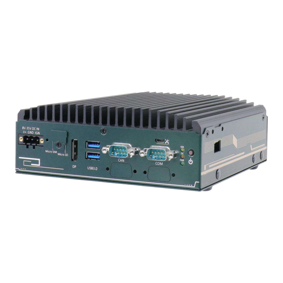
Page 19: Nru-52S Series Front Panel
NRU-52S Series NRU-52S Series Front Panel The front panel of the system features rich I/O ports, it has a 3-pin terminal block for DC input, Micro SIM slot, Micro SD slot, DisplayPort, USB3.2 Gen1 (USB3.0), CAN bus, COM, system status LEDs and a power button. Item Description 3-pin terminal... -
Page 20: 3-Pin Terminal Block For Dc And Ignition Control
NRU-52S Series 2.2.1 3-pin Terminal Block for DC and Ignition Control The system allows an 8 to 35V DC power input from via a 3-pin pluggable terminal block. The screw clamping mechanism is a reliable way to wire DC power. In addition to DC power, this terminal block also accepts ignition signal input (IGN). -
Page 21: Micro Sim Slot
NRU-52S Series 2.2.3 Micro SIM Slot The Micro SIM slot can be coupled with the M.2 B key and five antenna holes for 4G LTE or 5G NR module expansion. 2.2.4 MicroSD Slot Reserved for ODM purposes with Xavier NX. No function for standard systems. -
Page 22: Displayport
NRU-52S Series 2.2.5 DisplayPort The system has a DisplayPort (DP) output which is a digital display interface that mainly connect video source and carry audio to a display device. When connecting a DP, it can deliver up to 4K UHD (3840 x 2160 @ 60Hz) in resolution. The system is designed to support active DP adapter/ cable from NVIDIA’s recommended display adapters. -
Page 23: Can Bus Port
NRU-52S Series 2.2.7 CAN bus Port CAN bus is a robust industrial bus with a pair of differential signals and is commonly used in various industrial and in-vehicles applications. The system is equipped with a CAN bus DB9 port that is compatible with both industrial and in-vehicle applications. The CAN bus port supports CAN2.0A and CAN2.0B up to 1Mbps. -
Page 24: Microusb Port
NRU-52S Series 2.2.8 MicroUSB Port Reserved for system maintenance only. -
Page 25: Com Port
NRU-52S Series 2.2.9 COM Port The COM port is implemented via the NVIDIA Jetson module and can provide up to 115200 bps baud rate. The COM port is a DIP switch configurable RS-232/422/485 port. The operation mode can be set via the switch. -
Page 26: 2.2.10 System Status Leds
NRU-52S Series 2.2.10 System Status LEDs There are three LED indicators on the front panel: IGN, OS and PWR. The descriptions of these LEDs are listed in the following table. Indicator Color Description Yellow Ignition power control, lit when IGN signal is applied. Lit when Jetson module is powered on, and booted into device tree Green Power indicator, lit when the PCBA is powered on... -
Page 27: Nru-52S Series Rear Panel
NRU-52S Series NRU-52S Series Rear Panel The rear panel of NRU-52S systems feature a DIO & GPS PPS and four PoE ++ ports. Item Description DIO & GPS The DIO port provides 1x GPS PPS input, 3-CH isolated DI and 4-CH PPS port isolated DO Gigabit... -
Page 28: Dio & Gps Pps Port
NRU-52S Series 2.3.1 DIO & GPS PPS Port The system provides 1x GPS PPS input, 3-CH isolated DI and 4-CH isolated DO output channels. The DO is followed by open-drain design, i.e., the output voltage is decided by the external power source. -
Page 29: Ieee 802.3Bt Poe ++ Port
NRU-52S Series 2.3.2 IEEE 802.3bt PoE ++ Port The Gigabit PoE ++ port supply power and data on a standard CAT-5 or better Ethernet cable. Acting as a PSE (Power Sourcing Equipment), compliant with IEEE 802.3bt, it has a total power budget of 144W while each port can deliver up to 90W to a Powered Device (PD). -
Page 30: Grounding Point
NRU-52S Series 2.3.3 Grounding Point The system offers EMI protection with an isolated PCB design. If you are powering the NRU-52S using an isolated power supply, please make sure the chassis grounding point is connected. -
Page 31: Internal I/O
NRU-52S Series Internal I/O The system’s internal I/O connectors consist of an M.2 B key slot 5G/4G wireless communication module, and two mini PCIe slots for wireless or storage modules. 2.4.1 M.2 B Key 2242/ 3042/ 3052 & SIM Slots M.2 B key and internal SIM card slot SIM card slot on panel The system has an M.2 2242/ 3042/ 3052 slot (indicated in... - Page 32 NRU-52S Series M.2 (B Key) Slot Pin Definition Pin # Signal Pin # Signal +3V3 +3V3 FULL_CARD_POWER_OFF_N USB_D+ W_DISABLE_N USB_D- Mechanical Key USB3.0-RX- USB3.0-RX+ UIM1-RESET UIM1-CLK USB3.0-TX- UIM1-DATA USB3.0-TX+ UIM1-PWR UIM2-DET UIM2-DATA UIM2-CLK UIM2-RST UIM2-PWR RESET_N +3V3 +3V3 +3V3...
-
Page 33: Mini-Pcie Slots For Nru-52S
NRU-52S Series 2.4.2 mini-PCIe Slots for NRU-52S+ The mini-PCIe sockets (in blue) offer both PCIe and USB2.0 signals and accept off-the-shelf mini-PCIe modules. You can add additional features to your system such as 5G/ 4G, WiFi, GPS, CAN bus, analog frame grabber, etc. For wireless (WIFI/ 3G/ 4G) communication, multiple SMA antenna apertures can be located on the rear panel. - Page 34 NRU-52S Series mini-PCIe Pin Definition Pin # Signal Pin # Signal WAKE_N P3V3 P1V5 CLKREQ_N REFCLK- REFCLK+ Mechanical Key PERS_N PERn0 P3V3 PERp0 P1V5 SMB_CLK PETn0 SMB_DATA PETp0 USB_D- USB_D+ P3V3 P3V3 Reserved Reserved P1V5 Reserved P3V3 WARNING Some off-the-shelf mini-PCIe 4G modules are not compliant to standard mini-PCIe interface. They use 1.8V I/O signals instead of standard 3.3V I/O and may have signal conflict.
-
Page 35: Mini-Pcie Slots For Nru-52S
NRU-52S Series 2.4.3 mini-PCIe Slots for NRU-52S The mini-PCIe socket (in blue) offers PCIe and USB2.0 signal and the mini-PCIe socket (in red) offers USB2.0 signal. You can add additional features to your system such as 5G/ 4G, WiFi, GPS, CAN bus, analog frame grabber, etc. For wireless (WIFI/ 3G/ 4G) communication, multiple SMA antenna apertures can be located on the rear panel. - Page 36 NRU-52S Series mini-PCIe Pin Definition (in Blue) Pin # Signal Pin # Signal P3V3 P1V5 Mechanical Key P3V3 P1V5 SMB_CLK SMB_DATA USB_D- USB_D+ P3V3 P3V3 Reserved Reserved P1V5 Reserved P3V3 WARNING Some off-the-shelf mini-PCIe 4G modules are not compliant to standard mini-PCIe interface. They use 1.8V I/O signals instead of standard 3.3V I/O and may have signal conflict.
- Page 37 NRU-52S Series mini-PCIe Pin Definition (in Red) Pin # Signal Pin # Signal WAKE_N P3V3 P1V5 CLKREQ_N REFCLK- REFCLK+ Mechanical Key PERS_N PERn0 P3V3 PERp0 P1V5 SMB_CLK PETn0 SMB_DATA PETp0 USB_D- USB_D+ P3V3 P3V3 Reserved Reserved P1V5 Reserved P3V3 WARNING Some off-the-shelf mini-PCIe 4G modules are not compliant to standard mini-PCIe interface.
-
Page 38: Dip Switch For Com Port Configuration
NRU-52S Series 2.4.4 DIP Switch for COM Port Configuration The COM port configuration is controlled by DIP switches 1 and 2, while termination and slew rate are set via DIP switches 3 and 4. DIP switch DIP switch setting DIP switch DIP switch setting Mode Mode... -
Page 39: System Installation
NRU-52S Series System Installation Before disassembling the system enclosure and installing components and modules, please make sure you have done the following: ⚫ It is recommended that only qualified service personnel should install and service this product to avoid injury or damage to the system. ⚫... -
Page 40: Disassembling The System Enclosure
NRU-52S Series Disassembling the System Enclosure To install internal components such as M.2 SSD or mini-PCIe module, you need to disassemble the system enclosure. Please refer to the following procedure: 1. Turn the system upside-down and remove the six screws indicated. 2. -
Page 41: Installing Internal Components
NRU-52S Series Installing Internal Components 3.2.1 M.2 B Key 2242/ 3042/ 3052 & SIM Card Installation The system has an M.2 2242/ 3042/ 3052 slot (indicated in blue rectangle) with dual SIM slots (one indicated in rectangle, one situated in the front panel) supporting 5G/ 4G. A copper standoff is provided for you to secure onto the motherboard into the red arrow location for an... - Page 42 NRU-52S Series 4. Place the micro SIM card into position, place the cover over the micro SIM card, and slide the cover in the direction shown to lock the SIM card in place. 5. To install the antenna onto the system enclosure, clip on the IPEX-to-SMA cable to the module and secure the antenna to the side panel (refer to the module’s manual for clip-on connection).
-
Page 43: Mini-Pcie Module Installation
NRU-52S Series 3.2.2 mini-PCIe Module Installation There are two mini-PCIe slots on the main board. Please follow the procedures for installation. Disassemble the system enclosure. 2. To install, insert the gold finger end of the mini-PCIe card on a 45 degree angle into the slot, gently push the other end of the mini-PCIe onto the motherboard and secure it a screw. - Page 44 NRU-52S Series 3. To o install the antenna onto the system enclosure, clip on the IPEX-to-SMA cable to the module and secure the antenna to the side panel (refer to the module’s manual for clip-on connection). Clip on the IPEX-to-SMA cable Secure the connector body, coupling nut onto a antenna opening on a panel 4.
-
Page 45: Fan Kit Installation
NRU-52S Series Fan Kit Installation To install a fan kit, please follow the instructions below: Disassemble the system enclosure. 2. From the inside of the enclosure, remove the cover for the fan’s 4-pin power connector. Reinstall the enclosure when done. 4. - Page 46 NRU-52S Series 5. Take out the cable cover (indicated in rectangle) from the accessory box and secure it over the 4-pin power cable using the screws (indicated by the blue arrows) provided. 6. Secure the two hex screws on the other side panel to complete the fan kit installation.
-
Page 47: Installing The System Enclosure
NRU-52S Series Installing the System Enclosure To reinstall the system enclosure, turn the system upside-down (the heatsink fins at the bottom), place the bottom panel onto the enclosure and secure the screws indicated in the following illustration. -
Page 48: Wall Mount Installation
NRU-52S Series Wall Mount Installation To install the system as a wall mount device, please refer to the following instructions. To install the wall mount kit, please remove the four rubber stands at the bottom of the enclosure. - Page 49 NRU-52S Series Take out the two wall mount brackets (indicated in blue) and four M4 screws out of the accessory box. Fix the wall mount brackets to the system enclosure using M4 screws (indicated in red). Place the system on a flat surface portion of the wall and secure it with four (4) M4 screws.
-
Page 50: Powering On The System
NRU-52S Series Powering On the System 3.6.1 Powering On Using the Power Button This is the simplest way to turn on your system. The power button on the side panel is a non-latched switch and behaves as the ATX-mode on/off control. With DC power connected, pushing the power button will turn on the system and the PWR LED indicator will light up. -
Page 51: Ignition Power Control
NRU-52S Series Ignition Power Control The ignition power control module for in-vehicle applications is an MCU-based implementation that monitors the ignition signal and reacts to turn on/off the system according to predefined on/off delay. Its built-in algorithm supports other features such as ultra-low power standby, battery-low protection, system hard-off, etc. -
Page 52: Additional Features Of Ignition Power Control
NRU-52S Series 4.1.1 Additional Features of Ignition Power Control In addition to the typical timing correlation, the ignition power control module offers additional features to provide additional reliability for in-vehicle applications. ⚫ Low battery detection The ignition power control module continuously monitors the voltage of DC input when the system is operational. -
Page 53: Wiring Ignition Signal
NRU-52S Series 4.1.2 Wiring Ignition Signal To have ignition power control for in-vehicle usage, you need to supply IGN signal to the system. The IGN input is located on the 3-pin pluggable terminal block (shared with DC power input). For in-vehicle ignition control wiring, please do the following: 1. -
Page 54: Operation Modes Of Ignition Power Control
NRU-52S Series 4.1.3 Operation Modes of Ignition Power Control You can use the rotary switch to configure the operation mode. The system offers 16 (0~15) operation modes with different power-on/power-off delay configurations. The ignition rotary switch can be located once you remove the bottom panel. Please refer to Disassemble the system enclosure for instructions. - Page 55 NRU-52S Series ⚫ Mode 2 Mode 2 is designed to have a very minor power on/ off delay of 160ms for applications that requires the system to start up almost at the same as the rest of the equipment it is working in collaboration with.
-
Page 56: Reflashing The Nru System
NRU-52S Series Reflashing the NRU System To backup and restore pre-built the system, please refer to the following links: NRU-52S+ https://neousys.gitbook.io/nru-series/nru50/software-related/backup-and-restor e-pre-built-nvme NRU-52S https://neousys.gitbook.io/nru-series/nru50/software-related/flash/20221026-_ _-nru-52s-es2-es3 NRU FTP We put our latest released files on our FTP. Please contact your sales representative for the FTP info. - Page 57 NRU-52S Series Software Reminder NVIDIA tries to design an OTA mechanism to update the Jetson Xavier Computer from remote. However, as far as we tested, the OTA mechanism might damage the boot loader files and make NRU can’t boot anymore. Please make sure to call “sudo apt-mark hold nvidia-l4t-bootloader”...
Need help?
Do you have a question about the NRU-52S+ Series and is the answer not in the manual?
Questions and answers