Table of Contents
Advertisement
Quick Links
Advertisement
Table of Contents

Related Manuals for Neousys Technology Nuvo-2400 Series


Summary of Contents for Neousys Technology Nuvo-2400 Series
- Page 1 Nuvo-2400 User’s Manual Neousys Technology Inc. Nuvo-2400 Series Multi-Expansion Slots ® Intel Bay Trail Fanless Industrial Computer User’s Manual Rev. 1.1 Published Jul. 30th, 2018 Copyright © 2015 Neousys Technology Inc. All Right Reserved. Page 1 of 81...
- Page 2 This PCI Express slot utilizes x1 PCIe link and bandwidth → This PCI Express slot delivers 1 Gbit/s utilizes x1 PCIe link and delivers 4 Gbit/s bandwidth. Copyright © 2015 Neousys Technology Inc. All Right Reserved. Page 2 of 81...
-
Page 3: Table Of Contents
I/O I ........................27 NTERNAL NTERFACE 3.2.1 COM Ports ..........................27 3.2.2 Parallel Port..........................28 3.2.3 DDR3L SODIMM Socket ......................29 3.2.4 SATA Connector #1 ........................30 Copyright © 2015 Neousys Technology Inc. All Right Reserved. Page 3 of 81... - Page 4 Watchdog Timer for Booting ...................... 61 5.1.7 Select a Boot Device ........................62 ......................63 PERATING YSTEM UPPORT ........................64 RIVER NSTALLATION Install All Drivers Using “One-Click” Driver Installation .............. 64 5.3.1 Copyright © 2015 Neousys Technology Inc. All Right Reserved. Page 4 of 81...
- Page 5 InitDIO .............................. 75 6.3.2.2 DIReadLine ............................76 6.3.2.3 DIReadPort ............................77 6.3.2.4 DOWriteLine ............................ 78 6.3.2.5 DOWritePort ............................ 79 6.3.2.6 DOWriteLineChecked ........................80 6.3.2.7 DOWritePortChecked ........................81 Copyright © 2015 Neousys Technology Inc. All Right Reserved. Page 5 of 81...
-
Page 6: Figure
#2 ................. 44 IGURE BRACKET ASSEMBLY OF CONNECTOR 36: HDD SATA ..............45 IGURE BRACKET ASSEMBLY CONNECTED TO CABLE 37: W ..................45 IGURE EDGING THE BRACKET ASSEMBLY Copyright © 2015 Neousys Technology Inc. All Right Reserved. Page 6 of 81... - Page 7 DIO L ................68 IGURE OMPLETE IBRARY NSTALLATION 61: W ....................74 IGURE IRING OF ISOLATED DIGITAL INPUTS 62: W ..................... 74 IGURE IRING OF ISOLATED DIGITAL OUTPUTS Copyright © 2015 Neousys Technology Inc. All Right Reserved. Page 7 of 81...
-
Page 8: Table
IN DEFINITION OF REMOTE CONTROL CONNECTOR 14: F BIOS ........................55 ABLE UNCTION EYS IN 15: O ................60 ABLE PTIONS OF OWER N AFTER OWER AILURE Copyright © 2015 Neousys Technology Inc. All Right Reserved. Page 8 of 81... -
Page 9: Declaimer
This manual is intended to be used as a practical and informative guide only and is subject to change without prior notice. It does not represent commitment from Neousys Technology Inc. Neousys shall not be liable for direct, indirect, special, incidental, or consequential damages arising out of the use of the product or documentation, nor for any infringements upon the rights of third parties, which may result from such use. -
Page 10: Chapter 1 Introduction
Nuvo-2400 supports dual independent displays, dual 2.5" SATA bays and dual gigabit LAN ports with teaming and PXE. These features, together with the 3 expansion slots, maximize the flexibility of Nuvo-2400 for even more generic applications. Copyright © 2015 Neousys Technology Inc. All Right Reserved. Page 10 of 81... -
Page 11: Product Specification
Wall-mount (Standard) or DIN-rail mount (Optional) Maximal power consumption is measured with 100% CPU and 3D loading applied using Passmark® BurnInTest™ v8.0. No Ethernet connection and external PoE devices are connected. Copyright © 2015 Neousys Technology Inc. All Right Reserved. Page 11 of 81... - Page 12 IEC60068-2-64) Shock Operating, 50 Grms, Half-sine 11 ms Duration (w/ SSD, w/o add-on card, according to IEC60068-2-27) CE/FCC Class A, according to EN 55022 & EN 55024 Copyright © 2015 Neousys Technology Inc. All Right Reserved. Page 12 of 81...
-
Page 13: Specification Of Nuvo-2421
Wall-mount (Standard) or DIN-rail mount (Optional) Maximal power consumption is measured with 100% CPU and 3D loading applied using Passmark® BurnInTest™ v8.0. No Ethernet connection and external PoE devices are connected. Copyright © 2015 Neousys Technology Inc. All Right Reserved. Page 13 of 81... - Page 14 IEC60068-2-64) Shock Operating, 50 Grms, Half-sine 11 ms Duration (w/ SSD, w/o add-on card, according to IEC60068-2-27) CE/FCC Class A, according to EN 55022 & EN 55024 Copyright © 2015 Neousys Technology Inc. All Right Reserved. Page 14 of 81...
-
Page 15: Specification Of Di/O
Sink type Interface MOSFET, open drain Rated Driving Voltage 24VDC Max. Driving Voltage 30VDC Rated Driving Current 200mA Peak Driving Current On Time <2µs Off Time <0.3µs Copyright © 2015 Neousys Technology Inc. All Right Reserved. Page 15 of 81... -
Page 16: Chapter 2 Getting To Know Your Nuvo-2400
Nuvo-2400 2.1 Unpack your Nuvo-2400 When you receive the package of Nuvo-2400 Series, please check immediately if the package contains all the items listed in the following table. If any item is missing or damaged, please contact your local dealer or Neousys Technology Inc. for further assistance. -
Page 17: Chapter 3 I/O Interface
Please note that a 5 seconds interval is kept by the system between two on/off operations (i.e. once turning off the system, you shall wait for 5 seconds to initiate another power-on operation). Copyright © 2015 Neousys Technology Inc. All Right Reserved. Page 17 of 81... -
Page 18: Reset Button
The reset button is used to manually reset the system in case of any abnormal condition. To avoid unexpected operation, the reset button is hidden behind the front panel. You need to use a pin-like object to push the reset button. Copyright © 2015 Neousys Technology Inc. All Right Reserved. Page 18 of 81... -
Page 19: Led Indicators
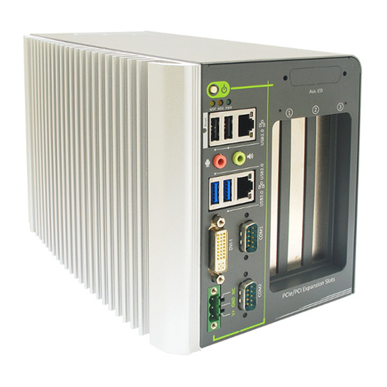
Nuvo-2400 User’s Manual 3.1.3 LED Indicators Figure 3: LED Indicators There are three LED indicators on the front panel of Nuvo-2400 Series. The following table describes the indicators. Table 5: Definition of Nuvo-2400 LED indicators Indicator Color Description Green Power indictor, lighted-up when system is on. -
Page 20: Gigabit Ethernet Ports
3.1.4 Gigabit Ethernet Ports Figure 4: Gigabit Ethernet Ports ® Nuvo-2400 Series offers 2 Gigabit Ethernet ports using Intel Ethernet Controller I210. When plugging in the Ethernet cable, you can tell the Ethernet status and speed from the LED indicators on the RJ45 connector. The following tables provide the definition of the LEDs. -
Page 21: Dvi-I
3.1.5 DVI-I Figure 5: DVI-I connector Nuvo-2400 Series has a DVI-I connector. This connector provides DVI/HDMI and VGA display outputs. The DVI/HDMI output can be either DVI signals or HDMI signal depending on the display device connected and support the resolution up to 2560 x 1600, and the VGA output supports the resolution up to 2560 x 1600. -
Page 22: Software-Programmable Com Ports
3.1.6 Software-programmable COM Ports Figure 6: Software-programmable COM ports Nuvo-2400 Series provides two software-selectable COM ports for communicating with external devices. Each port supports RS-232/422/485, and the operation mode of each port can be set in BIOS setup utility. COM ports are implemented using industrial-grade ITE 8783 Super IO chip (-40 to 85°C) and provide up to 115200 bps baud rate. -
Page 23: Usb Connectors
Figure 7: USB2.0 connectors (left) and USB3.0 connector (right) There are totally 1 USB3.0 port and 3 USB2.0 ports on Nuvo-2400 Series. By BIOS default, one USB 3.0 port is operated in xHCI (eXtensible Host Control Interface) mode and is compatible to USB 3.0, USB 2.0, USB 1.1 and USB 1.0 devices. -
Page 24: Speaker-Out And Mic-In Jacks
3.1.8 Speaker-out and Mic-in Jacks Figure 8: Mic-in and speaker-out Nuvo-2400 Series provides audio functions using Intel HD Audio and Realtek ALC262 Codec. There are two audio jacks. The pink one is used for microphone input, and the green one is for speaker output. To utilize the microphone input function in Windows, you need to install corresponding drivers for both Intel HD Audio and Realtek ALC262 Codec. -
Page 25: Dc Input
3.1.9 DC Input Figure 9: DC-input connector Nuvo-2400 Series features a pluggable terminal block for direct DC wiring. The 3-pin pluggable terminal block is fit for field usage where DC power is usually provided. It accepts a wide range of DC power input from 8~25V DC. And the screw clamping connection of terminal block gives a very reliable way for wiring the DC power. -
Page 26: Isolated Di/O
3.1.10 Isolated DI/O Figure 10: Isolated DI/O connector Nuvo-2400 Series offers an option of on-board 3750 Vrms isolated DIO for extending application range. This option provides 8 channels of isolated digital input and 8 channels of isolated digital output via a 25-pin D-sub connector. The following table shows the pin definition of the DI/O connector. -
Page 27: Internal I/O Interface
3.2.1 COM Ports Figure 12: Internal COM ports Nuvo-2400 Series provides two COM ports for communicating with external devices. Each port supports RS-232 only. COM ports are implemented using industrial-grade ITE 8783 Super IO chip (-40 to 85°C) and provide up to 115200 bps baud rate. The following table describes the pin definition of two COM ports. -
Page 28: Parallel Port
3.2.2 Parallel Port Figure 13: Internal parallel port Nuvo-2400 Series provides one parallel port for connecting a printing device. The parallel port is implemented using industrial-grade ITE 8783 Super IO chip (-40 to 85°C) and has pin-out via a 2x13, 2.0mm pitch box header. For users who need to connect a printing device via a standard a 25-pin D-sub connector, Neousys Technology Inc. -
Page 29: Ddr3L Sodimm Socket
3.2.3 DDR3L SODIMM Socket Figure 15: DDR3L SODIMM socket Nuvo-2400 Series provides one 204-pin SODIMM socket for memory installation. It supports a maximal 8GB capacity by installing one low-voltage 1.35V DDR3L-1333 SODIMM modules. For information of installing DDR3L memory modules, please refer to the section “Install an DDR3L SO-DIMM Module”. -
Page 30: Sata Connector #1
HDD bracket shipped with Nuvo-2400, you can directly mount a 2.5” HDD or SSD to this port. For information of installing a HDD/SSD to SATA port #1, please refer to the section "Install an 2.5" HDD/SSD on SATA Connector #1". Copyright © 2015 Neousys Technology Inc. All Right Reserved. Page 30 of 81... -
Page 31: Sata Connector #2
2.5” HDD/SSD. The second HDD bracket is located on the bottom side of the chassis. For information of installing a HDD/SSD to SATA connector #2, please refer to the section “Install an 2.5" HDD/SSD on SATA Connector #2” for detail. Copyright © 2015 Neousys Technology Inc. All Right Reserved. Page 31 of 81... -
Page 32: Remote Status Output
3.2.6 Remote Status Output Figure 18: Remote status output connector For an application which places Nuvo-2400 Series inside a cabinet, it's useful to output the system status to external LED indicators so that users can check how the system's running. -
Page 33: Remote On/Off Control
Both AT-mode and ATX-mode on/off control are supported. For detail information of using remote on/off control function, please refer to section “Power on Using an External Latched Switch” and “Power on Using an External Non-latched Switch”. Copyright © 2015 Neousys Technology Inc. All Right Reserved. Page 33 of 81... -
Page 34: Expansion Slot
The maximal supported card size is 205mm x 105mm. The following figure shows the definition of the card size. And this size applies to both PCI and PCIe cards. Figure 20: Maximum PCB size of add-on card supported by Nuvo-2400 Copyright © 2015 Neousys Technology Inc. All Right Reserved. Page 34 of 81... -
Page 35: Pci Slot
3.3.1 PCI slot Figure 21: PCI Slots of Nuvo-2430(left) and Nuvo-2421(right) PCI slots are located on the backplane of Nuvo-2400 Series. Nuvo-2430 provides three PCI slots and Nuvo-2421 provides two PCI slots. These PCI slots support 5V PCI bus. For information of installing PCI cards, please refer to the section “Install an Add-on Card”. -
Page 36: Pci Express X4 Slot
12W to limit the heat generated by add-on cards and maintain the system stability. For applications need add-on cards which consume more than 12W, the fan option is suggested to maintain a reasonable temperature inside the chassis. Please contact Neousys Technology for the fan option. -
Page 37: Mechanical Dimension
Nuvo-2400 User’s Manual 3.4 Mechanical Dimension Front View Figure 23: Front view of Nuvo-2400 Side View (Right) Figure 24: Side view (right) of Nuvo-2400 Copyright © 2015 Neousys Technology Inc. All Right Reserved. Page 37 of 81... - Page 38 Nuvo-2400 User’s Manual Bottom View Figure 25: Bottom view of Nuvo-2400 Back View Figure 26: Back view of Nuvo-2400 Copyright © 2015 Neousys Technology Inc. All Right Reserved. Page 38 of 81...
-
Page 39: Chapter 4 Getting Started
Please follow the correct procedures to prevent any damage on your Nuvo-2400 Series" 4.1 Remove the Side Cover Nuvo-2400 Series has a side cover. After removing the cover, you can see the internal I/O of Nuvo-2400. Please follow the instructions to remove the side cover. -
Page 40: Install An Add-On Card
Figure 29: 3-point fixation of a PCI/PCIe card Get the M3 PW-head screw from the accessory box. And use it to fix your PCI/PCIe add-on card. Copyright © 2015 Neousys Technology Inc. All Right Reserved. Page 40 of 81... -
Page 41: Install An Ddr3L So-Dimm Module
Nuvo-2400 User’s Manual 4.3 Install an DDR3L SO-DIMM Module Nuvo-2400 Series provides one 204-pin, SODIMM socket for installing 1.35V DDR3L memory module. You can install/replace the memory modules according to the following the steps. NOTE Installing incorrect memory module might damage the system or result in system failure. Please make sure you're installing a 1.35V DDR3L SODIMM module. -
Page 42: Install An 2.5" Hdd/Ssd On Sata Connector #1
SBC. Figure 32: Installed HDD bracket assembly Fasten the HDD bracket assembly with three M3, L16 P-head screws. Copyright © 2015 Neousys Technology Inc. All Right Reserved. Page 42 of 81... -
Page 43: Install An 2.5" Hdd/Ssd On Sata Connector #2
Figure 33: SATA cable connected to SATA connector #2 Put the chassis upside down. You can see the cover of HDD bracket exposed. Loose the screw to open and remove it. Copyright © 2015 Neousys Technology Inc. All Right Reserved. Page 43 of 81... - Page 44 Note that the HDD must be placed in a right direction. Figure 35: HDD bracket assembly of SATA connector #2 Connect the HDD bracket assembly to the 22-pin connector of the SATA cable. Copyright © 2015 Neousys Technology Inc. All Right Reserved. Page 44 of 81...
- Page 45 Once it’s firmly wedged, push it down and fix it using a M3 flat-head screw. Now you’ve done the installation of HDD for SATA connector #2. Figure 37: Wedging the HDD bracket assembly Copyright © 2015 Neousys Technology Inc. All Right Reserved. Page 45 of 81...
-
Page 46: Mount Your Nuvo-2400
For the best efficiency of heat dissipation, please ensure your system in a correct orientation, as shown in the following figure. Figure 38: Correct Orientation of Mounting your System Copyright © 2015 Neousys Technology Inc. All Right Reserved. Page 46 of 81... -
Page 47: Mount Your Nuvo-2400 On The Wall
Fix Nuvo-2400 on the wall via the screw holes of the mounting bracket. You can also take advantage of the keyhole-shaped holes of the mounting bracket to suspend Nuvo-2400 on the Wall. Figure 40: Dimension of screws holes for back side mounting Copyright © 2015 Neousys Technology Inc. All Right Reserved. Page 47 of 81... -
Page 48: Mount Your Nuvo-2400 On The Din-Rail
Nuvo-2400 using four M4 flat-head screws before mount it to a DIN rail. This option can be useful if you want to deploy Nuvo-2400 inside an equipment cabinet where DIN rail is available. Figure 41: Assembling the DIN rail mounting clip Copyright © 2015 Neousys Technology Inc. All Right Reserved. Page 48 of 81... -
Page 49: Mount Your Nuvo-2400 On A Flat Surface
Figure 42: Assembling the mounting bracket on the bottom side Fix Nuvo-2400 on a flat surface via the screw holes of two mounting brackets. Figure 43: Dimension of screw holes for bottom side mounting Copyright © 2015 Neousys Technology Inc. All Right Reserved. Page 49 of 81... -
Page 50: Connect Dc Power To Nuvo-2400
Nuvo-2400 User’s Manual 4.7 Connect DC Power to Nuvo-2400 Nuvo-2400 Series uses a 3-pin pluggable terminal block to accept from 8~25V DC power input. It provides the way for directly wiring the DC power. To connect DC power via the 3-pin pluggable terminal block, please follow the steps listed below. -
Page 51: Power On Your Nuvo-2400
When the latched switch is closed, the DC power is break off and system is turn off. When the latched switch is opened, the DC power is feed-in, and the system is turn on. Copyright © 2015 Neousys Technology Inc. All Right Reserved. Page 51 of 81... -
Page 52: Power On Using An External Non-Latched Switch
If your operating system supports ATX power mode (i.e. Microsoft Windows or Linux), push the power button causes a pre-defined system behavior, such as shutdown or hibernation. Copyright © 2015 Neousys Technology Inc. All Right Reserved. Page 52 of 81... -
Page 53: Power On Using Wake-On-Lan Function
S4 (Hibernate) or S5 (system off with standby power) state via issuing Subnet Directed Broadcasts (SDB) or a magic packet. Nuvo-2400 Series implements the Wake-on-LAN function for its first GbE port. To enable WOL function and power on your system, please follow the steps listed below. - Page 54 Wake on Magic Packet from power off state Checking this option enables your system to wake up from S5 (system off with standby power) state upon receiving a magic packet. Copyright © 2015 Neousys Technology Inc. All Right Reserved. Page 54 of 81...
-
Page 55: Chapter 5 Bios And Driver
BIOS options. Table 14: Function Keys in BIOS Keys Function Help ↑↓←→ Select Item F5/F6 Change Values Load Setup Defaults Exit Enter Select -> SubMenu Save and Exit Copyright © 2015 Neousys Technology Inc. All Right Reserved. Page 55 of 81... -
Page 56: Com1 & Com2 Operation Mode
Go to [Advanced] / [Peripheral Configuration] Set the [Set COM1 as] option to a proper mode for COM1 of your Nuvo-2400. Figure 50: Setting Modes of COM Port in BIOS Copyright © 2015 Neousys Technology Inc. All Right Reserved. Page 56 of 81... -
Page 57: Chipset Sata Mode
Go to [Advanced] / [SATA Configuration]. Set the [Chipset SATA Mode] option to a proper mode for your Nuvo-2400. Figure 51: Setting Modes of SATA Mode in BIOS Copyright © 2015 Neousys Technology Inc. All Right Reserved. Page 57 of 81... -
Page 58: C-States And Max C-States
Go to [Power] / [Advanced CPU Control]. Enable/disable the [C-States] option according to your application. Configure the [Max C-States] option according to your application. Figure 52: Configuring C-States in BIOS Copyright © 2015 Neousys Technology Inc. All Right Reserved. Page 58 of 81... -
Page 59: Wake-On-Lan Option
When Nuvo-2400 boots up, press F2 to enter BIOS setup utility. Enable/disable the [Wake on LAN] option according to your application. Figure 53: Enabling Wake on LAN in BIOS Copyright © 2015 Neousys Technology Inc. All Right Reserved. Page 59 of 81... -
Page 60: Power On After Power Failure Option
S0 – Power On System is powered on when DC power is supplied. S5 – Power Off System is kept in off state when DC power is supplied. Copyright © 2015 Neousys Technology Inc. All Right Reserved. Page 60 of 81... -
Page 61: Watchdog Timer For Booting
Once you give a timeout value, the [WDT Stop Option] option appears. You can select either [Automatically after POST] or [Manually after Entering OS]. Figure 55: Configuring WDT in BIOS Copyright © 2015 Neousys Technology Inc. All Right Reserved. Page 61 of 81... -
Page 62: Select A Boot Device
Floppy Drive Others You can use F5/F6 or +/- to change the boot order of devices or device types. Figure 56: Configuring order of booting devices in BIOS Copyright © 2015 Neousys Technology Inc. All Right Reserved. Page 62 of 81... -
Page 63: Operating System Support
You can visit Intel website for further information. Neousys will keep this list updated as we continuously test other operating systems with Nuvo-2400. Please contact us for the latest OS support list. Copyright © 2015 Neousys Technology Inc. All Right Reserved. Page 63 of 81... -
Page 64: Driver Installation
Nuvo-2400 User’s Manual 5.3 Driver Installation Neousys Technology Inc. provides a very convenient utility in “Drivers & Utilities DVD” to allow the “One-Click” driver installation. This utility automatically detects your Windows operating system and installs all necessary drivers to your Nuvo-2400 with just one mouse click. -
Page 65: Install Drivers Manually
Chipset driver (x:\Driver_Pool\Chipset_Vlv\Win7_8_ALL\SetupChipset.exe) Graphics driver (x:\Driver_Pool\Graphics_3rd_i7_Vlv\Win7_8_32\Setup.exe) Audio driver (x:\Driver_Pool\Audio_ALC262\Win7_8_ALL\Setup.exe) LAN driver (x:\Driver_Pool\GbE_I210\Win7_8_32\APPS\PROSETDX\Win32\DxSetup.exe) TXE driver (x:\Driver_Pool\TXE_Vlv\Win8_ALL\SetupTXE.exe) Embedded IO (x:\Driver_Pool\IO_Vlv\Win8_32\Setup.exe) Windows 8/8.1 64-bit The recommended driver installation sequence is Copyright © 2015 Neousys Technology Inc. All Right Reserved. Page 65 of 81... - Page 66 Nuvo-2400 User’s Manual Chipset driver (x:\Driver_Pool\Chipset_Vlv\Win7_8_ALL\SetupChipset.exe) Graphics driver (x:\Driver_Pool\Graphics_3rd_i7_Vlv\Win7_8_64\Setup.exe) Audio driver (x:\Driver_Pool\Audio_ALC262\Win7_8_ALL\Setup.exe) LAN driver (x:\Driver_Pool\GbE_I210\Win7_8_64\APPS\PROSETDX\Winx64\DxSetup.exe) TXE driver (x:\Driver_Pool\TXE_Vlv\Win8_ALL\SetupTXE.exe) Embedded IO (x:\Driver_Pool\IO_Vlv\Win8_64\Setup.exe) Copyright © 2015 Neousys Technology Inc. All Right Reserved. Page 66 of 81...
-
Page 67: Chapter 6 Using Watchdog Timer And Dio
Click “Next >” and specify the directory of installing related files. The default directory is C:\Neousys\WDT_DIO. Figure 59: Set Installation Folder of WDT and DIO Library Once the installation is finished, a dialog appears to prompt you to reboot the system. Copyright © 2015 Neousys Technology Inc. All Right Reserved. Page 67 of 81... - Page 68 Figure 60: Complete WDT and DIO Library Installation When you programming your WDT or DIO program, the related files are located in Header File: \Include Library File: \Lib Function Reference: \Manual Sample Code: \Sample\ Copyright © 2015 Neousys Technology Inc. All Right Reserved. Page 68 of 81...
-
Page 69: Using Wdt Function
Initialize the WDT function. You should always invoke InitWDT() before set or start watchdog timer. Parameter None Return Value Returns TRUE if initialization successes, FALSE if initialization failed. Usage BOOL bRet = InitWDT() Copyright © 2015 Neousys Technology Inc. All Right Reserved. Page 69 of 81... -
Page 70: Setwdt
If value of unit is correct (0 or 1), this function returns TRUE, otherwise FALSE. Usage WORD tick = 255; BYTE unit = 1; //unit is second. BOOL bRet = SetWDT(tick, unit); //timeout value is 255 seconds Copyright © 2015 Neousys Technology Inc. All Right Reserved. Page 70 of 81... -
Page 71: Startwdt
0, the WDT expires and system resets. Parameter None Return Value If the timeout value is given in correct format, this function returns TRUE, otherwise FALSE. Usage BOOL bRet = StartWDT() Copyright © 2015 Neousys Technology Inc. All Right Reserved. Page 71 of 81... -
Page 72: Resetwdt
StopWDT is invoked before WDT is counted to 0, the WDT expires and system resets. Parameter None Return Value Always returns TRUE; Usage BOOL ret = ResetWDT() Copyright © 2015 Neousys Technology Inc. All Right Reserved. Page 72 of 81... -
Page 73: Stopwdt
Stop the countdown of WDT. When WDT is stopped, the WDT LED indicator stops blinking. Parameter None Return Value Always returns TRUE; Usage BOOL ret = StopWDT() Copyright © 2015 Neousys Technology Inc. All Right Reserved. Page 73 of 81... -
Page 74: Using Dio Function
GND return path is established. The digital output function on Nuvo series supports sinking current connection. The following diagrams are the suggested wiring for DO: Figure 62: Wiring of isolated digital outputs Copyright © 2015 Neousys Technology Inc. All Right Reserved. Page 74 of 81... -
Page 75: Dio Function Reference
Initialize the DIO function. You should always invoke InitDIO() before write/read any DIO port/channel. Parameter None Return Value Returns TRUE if initialization successes, FALSE if initialization failed. Usage BOOL bRet = InitWDT() Copyright © 2015 Neousys Technology Inc. All Right Reserved. Page 75 of 81... -
Page 76: Direadline
BYTE value specifies the DI channel to be read. Valid values are 0~3. Return Value The status (TRUE or FALSE) of the specified DI channel. Usage BYTE ch=3; //DI channel #3 BOOL DIChValue = DIReadLine(ch); //read DI channel #3 Copyright © 2015 Neousys Technology Inc. All Right Reserved. Page 76 of 81... -
Page 77: Direadport
Read the entire isolated digital input port (8 channels). Parameter None Return Value A WORD value indicates the status of DI port. Return value are 0~255. Usage WORD DIPortValue = DIReadPort (); Copyright © 2015 Neousys Technology Inc. All Right Reserved. Page 77 of 81... -
Page 78: Dowriteline
BOOL value (TRUE or FALSE) specifies the status of DO channel. Return Value None Usage BYTE ch=3; //DI channel #3 BOOL DOChValue=TRUE; DOWriteLine(ch, DOChValue); //write DO channel #3 as TRUE Copyright © 2015 Neousys Technology Inc. All Right Reserved. Page 78 of 81... -
Page 79: Dowriteport
WORD value specifies the status of the DO port. Valid values are 0~255. Return Value None Usage WORD DOPortValue=0XFF; //11111111b DOWritePort(DOPortValue); //write DO port as 11111111b Copyright © 2015 Neousys Technology Inc. All Right Reserved. Page 79 of 81... -
Page 80: Dowritelinechecked
BOOL value (TRUE or FALSE) specifies the status of DO channel. Return Value None Usage BYTE ch=3; //DI channel #3 BOOL DOChValue=TRUE; DOWriteLineChecked(ch, DOChValue); //write DO channel #3 as TRUE Copyright © 2015 Neousys Technology Inc. All Right Reserved. Page 80 of 81... -
Page 81: Dowriteportchecked
WORD value specifies the status of the DO port. Valid values are 0~255. Return Value None Usage WORD DOPortValue=0XFF; //11111111b DOWritePortChecked(DOPortValue); //write DO port as 11111111b Copyright © 2015 Neousys Technology Inc. All Right Reserved. Page 81 of 81...
Need help?
Do you have a question about the Nuvo-2400 Series and is the answer not in the manual?
Questions and answers