Advertisement
Quick Links
Advertisement

Related Manuals for TMG 1260


Summary of Contents for TMG 1260
- Page 1 Page 0 of...
-
Page 2: Main Specifications
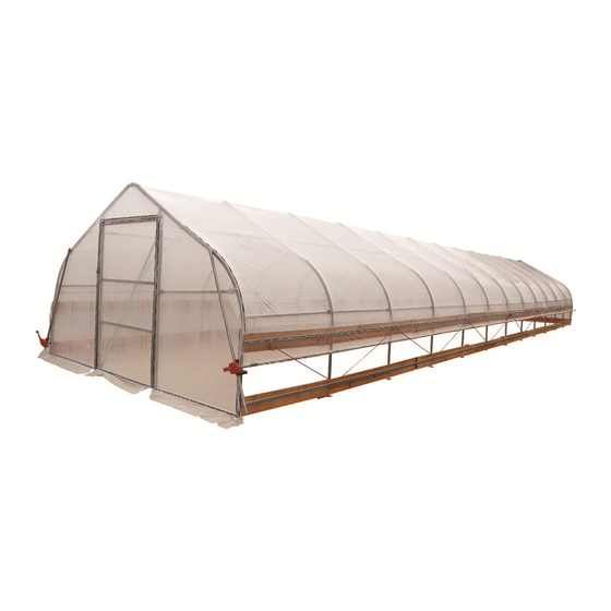
Main specifications Overall assembled size : L18.2 x W3.66 x H2.2 (m) / L60 x W12 x H7.2 (ft) Shoulder height : H1.2 (m) / 4ft Door : W1.2 x H1.8 (m) / 4 x 6 (ft) Prior to assembly Please read the instructions carefully before installation. - Page 3 TMG-GH126007 Part List Parts Graphical Description code Peak arch tube Upper rafter tube Shoulder tube Sidewall tube Roof purlin (horizontal tube) Base plate Door column base plate Expansion bolt M10x100mm Front door cross tubes Rear door cross tubes Upper vertical tubes for rear truss...
- Page 4 Roll film tube 2 group Tube clamp Door buckle Film rolling machine Reed groove Clip spring Eight clip spring Pressure film carrier Half round head bolt M6x50 Hex bolt M6x45 Hex bolt M6x80 Self tapping screw #12x25 Self tapping screw #12x35 Self tapping screw #12x35 Socket wrench Page 3 of...
- Page 5 Hex wrench Square plug Round plug Braided rope 1 bundle Adhesive tape 1 volume Film Board 80 metres (not included) Installation steps Step 1 : Review the whole structure and choose the proper installation site Choose a solid flat level ground area to set up the building. Do not install the building on soft ground, wetland, uneven surfaces, sloped surfaces.
- Page 6 (31) Base plate (#6) (2) Door column base plate (6A) (66) Expansion bolts (6B) Figure 1 Step 2 : Assemble all trusses The building includes 15 trusses , Connect all pipes with hex bolt (#26). Parts used in this step (refer to figure 2) : (1x15) Peak arch tube (#1) (2x15) Upper rafter tube (#2) (2x15) Shoulder tube (#3)
- Page 7 Figure 2 Lay down all (15) trusses on the ground as figure 3 when the assembly is all completed and before moving to next step. Figure 3 Step 3 : Put up all trusses (refer to figure 4) Put up the front truss, use hex bolt (#26) to secure the truss to the base plates.
- Page 8 Figure 4 Repeat above step to put up all other trusses (from 2th to 15th truss), and connect all purl ins. Now the whole structure is completely up. (refer to figure Parts used in this step : (70) Roof purlin (#5) (5x15) Half round head bolt (#25) Figure 5 Page 7 of...
- Page 9 Step 4 : Installation of front and rear trusses Installation of the front truss. (refer to figure 6) (2) Front door cross tubes (#7) (1) Door frame cross pull tube (#11) (1) Door frame left tube (#12) (1) Door frame right tube (#13) (1) Door frame column left tube (#14) (1) Door frame column right tube (#15) (4) Door horizontal tube (#16)
- Page 10 Figure 7 The whole structure inspection: check all components and trusses to make sure the whole structure is squared to the base line drawn at the step 1. All trusses must be set up righted at 90 degree. All purl ins must be straight in line. If any purl ins are not in line with they will need to be corrected before moving to the next step.
- Page 11 Figure 8 Figure 9 Step 6 : Install the film and roll film system (refer to figure 10) NOTE : The cover must be installed on a windless day. DO NOT attempt to install the cover during windy conditions. when you are ready to install the roof cover, unpack the cover and position it parallel to the building frame on one side.
- Page 12 the cover must be pulled over the top of the truss frame without being snagged or stressed on any frame members. tighten the film evenly to eliminate wrinkles and make the film flat and smooth. Do not over-tighten during the adjustment process, otherwise it will cause unnecessary damage.
-
Page 13: After The Installation
Figure 10 After the Installation Walk around and inspect the shelter periodically to make sure all components are still firmly secured and the whole shelter is well supported. Check all bolts and nuts as well as all connection points to make sure they are all in good position. We strongly recommend you remove any snow from the roof immediately.
Need help?
Do you have a question about the 1260 and is the answer not in the manual?
Questions and answers