Table of Contents
Advertisement
Quick Links
Advertisement
Table of Contents

Subscribe to Our Youtube Channel
Related Manuals for Ergomotion STOW


Summary of Contents for Ergomotion STOW
- Page 1 STOW A d j us t ab l e B as e S to ra ge B ed O w ne r's Ma nual...
-
Page 2: Table Of Contents
Safety Precautions and Usage Statements Shroud Installation Parts (Found in Shroud Carton) Adjustable Base Parts (Found in Adjustable Base Carton) Base Overview Electronic Overview STOW Shroud Assembly STOW Adjustable Base Installation Remote Control Remote Control Pairing Battery Backup Strap Troubleshooting Warranty... -
Page 3: Safety Precautions And Usage Statements
IN-HOME USE AND HOSPITAL STANDARDS: Overloading the storage base could cause it to rapidly close Ergomotion adjustable bed bases are designed solely for in- and cause serious harm or bodily injury. home use. This base was not designed as a hospital bed and is not designed to meet hospital standards. - Page 4 Wear and tear is damage that naturally and inevitably occurs as TOLERANCE a result of normal use or aging. All Ergomotion adjustable foundations, depending on make and model, are designed and manufactured to perform and function FABRIC CARE: within designated quality control parameters. Bases are subject...
- Page 5 Safety precautions and usage statements IMPORTANT DO’S AND DON’TS FCC Compliance: • Plug your adjustable base into a power surge protector. NOTE: This equipment has been tested and found to comply with • Evenly distribute weight when sleeping in a split setup. the limits for a Class B digital device, pursuant to part 15 of the FCC Rules.
-
Page 6: Shroud Installation Parts (Found In Shroud Carton)
Shroud Installation Parts (Found in Shroud Carton) Always use two people when setting up the base. A) Bottom panel head & foot x2 H) Support beam Corner support bracket x4 Crescent wrench C) Head shroud section (marked H) Hex key D) Bottom panel middle x2 Felt bumper pads x6 Left shroud section... -
Page 7: Adjustable Base Parts (Found In Adjustable Base Carton)
Adjustable Base Parts (Found in Adjustable Base Carton) Before discarding the packing materials, ensure all the parts are accounted for. All electron- ics and components that need to be installed are located in boxes under the base or at- tached to the frame. A)A) A) Remote control H) Crescent wrench... -
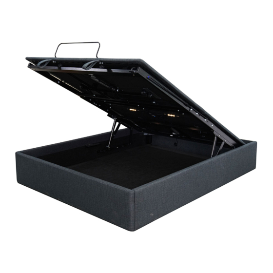
Page 8: Base Overview
Base Overview Head Motor USB A+C USB A+C Control Box Underbed Lighting Channel Bracket Prop Rod Foot Motor - 8 -... -
Page 9: Electronic Overview
Electronic Overview Not to scale. For illustration purposes only. Read all instructions before beginning installation. Battery Backup Strap Underbed Lighting Power Cord USB A+C Remote Control Power Supply Input Cord Control HEAD FOOT Foot Motor Head Motor - 9 -... -
Page 10: Stow Shroud Assembly
STOW Shroud Assembly Take the head, foot, and side shroud sections out of the carton. Remove the orange zip ties and bubble wrap from the air rods. Do this for each side. Remove the nut and one washer from the stud pictured below. - Page 11 STOW Shroud Assembly Arrange the head, foot, left and right shroud sections in the proper orientation. Slide the slotted corner brackets over the partially installed screws (may need to loosen for install) on the head shroud section (marked H). Repeat for all four corners, then tighten both screws in each corner using the M8 hex key.
- Page 12 STOW Shroud Assembly Remove adhesive on felt bumper pads and insert pegs into holes on each corner support bracket and center rest. Install all four bottom panels. Note: Panels with corner cutouts should align with the corners of the shroud. To install the head bottom panel, slide under the gas strut assembly.
-
Page 13: Stow Adjustable Base Installation
STOW Adjustable Base Installation Place the bed base box in a desired location with the bottom of the box facing up. Remove the binding straps and packing materials, making sure not to puncture the box with any sharp objects. Remove the bed base from the box. Unfold the bed making sure to keep the underside of the base facing Important: In order to keep base from folding during use, install the channel bracket across the hinge on both sides of the frame using the included M8 buttonhead screws, washers, and nuts. - Page 14 STOW Adjustable Base Installation Use two capable people to lift the adjustable base into alignment with the gas strut assembly. Note: The two partially installed M10 screws should insert into the keyway holes on the gas strut assembly. Important: Install the remaining two M10 screws and be sure to fully tighten all four M10 screws before use.
- Page 15 Install the prop rod. The prop rod is used as a secondary safety device that can be rotated downwards to secure the STOW in an open position. Secure it in place with the provided cotter pin. Uncoil Input Power Cord (connected to Control Box's power port) and plug into Power Supply.
- Page 16 STOW Adjustable Base Installation Locate the battery backup strap and install (2) 9V Alkaline batteries (not included). Store the strap in a convenient location in case of an emergency power outage. For operating instructions see page Install mattress retainer bars by inserting both ends of the retainer bar into the holes on the platform, and then lock the plastic snaps from under the bedplate to secure the mattress retainer bar.
-
Page 17: Remote Control
Remote Control The remote control arrives paired to the adjustable base. Three (3) AAA batteries are required to operate the remote. REMOTE FUNCTIONS A. Head Articulation: Raises and lowers the head end of the adjustable base. B. Foot Articulation: Raises and lowers the foot end of the adjustable base. -
Page 18: Remote Control Pairing
Remote control pairing The original remote that comes in the box is already paired to the adjustable base. No further action is required. In the event that the remote is not paired with the base, follow the steps below. Unplug the Power Cord from your power outlet. Remove the cover on the back of each remote Wait 1 minute, then plug it back in to your power and hold the PAIR button. -
Page 19: Battery Backup Strap
Battery backup strap (optional) For emergency use only, in case of a power outage. Batteries are not to be used for normal operation of the bed. Connect the Battery Backup Strap to the input Disconnect the Power Supply from the input power cord. -
Page 20: Troubleshooting
Troubleshooting If one or more functions on the bed base have stopped operating: • Check under the bed base to verify that the wired connections are secure and that there are no cords or bedding obstructing the movement of the base. •... - Page 21 The purchaser shall pay This warranty requires notice to be given 1/5 of the current MSRP of the replacement part, or to Ergomotion of any claim for repairs or the entire adjustable base if deemed irreparable at replacement parts.
- Page 22 This warranty is only valid in The United States, Canada and Puerto Rico. For all other jurisdictions, this Limited Product Warranty is valid only in the jurisdictions where the Products are sold by an Ergomotion authorized - 22 -...
- Page 23 US Customer Service ©2024 Ergomotion Inc V001_1/2024 Phone US 1-888-550-3746 US 1-805-979-9399 Email info@ergomotion.com www.ergomotion.com - 23 -...
Need help?
Do you have a question about the STOW and is the answer not in the manual?
Questions and answers