Table of Contents
Advertisement
Advertisement
Table of Contents

Related Manuals for Ergomotion 390 Series


Summary of Contents for Ergomotion 390 Series
- Page 1 OWNER’S MANUAL installation & operation Series 390...
-
Page 2: Table Of Contents
table of contents Safety Precautions and Usage Statements . . . . . . . . . . . . . . . . . . . . . . . . . . . . . . . . . . . . . . . . . . . . . . . 1-2 Parts List . -
Page 3: Safety Precautions And Usage Statements
In-Home Use and Hospital Disclaimer: Discontinue use of the bed base and contact a qualified service center Ergomotion adjustable bed bases are designed solely for in-home if: it has a damaged cord or plug, if it is not working properly, or it has use. - Page 4 safety precautions and usage statements smothering risk to small children and pets. To avoid injury, it is not Acoustics: advised to allow children and small pets to play on or under the bed. The massage function will emit a noticeable tone during operation. Children should not operate the bed base without adult supervision.
-
Page 5: Parts List
All electronics and components that need to be installed are located in boxes under the base or attached to the frame . Wireless Remote Control and (3) AAA batteries Mattress Retainer Bar (1)* (Optional, can be purchased from Ergomotion directly) Legs (4) Power Cord (1) Power Supply (1) -
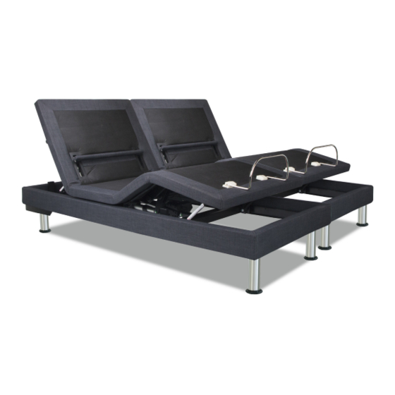
Page 6: Base Overview
base overview USB Charger Foot Motor Head Massage Foot Massage Motor Motor Head Tilt Motor LED Light Lumbar Motor Head Motor Control Box Power Down Box... -
Page 7: Quick Reference Guide
quick reference guide Not to scale . For illustration purposes only . Read all instructions before beginning installation . Connection to media faceplates (installed VIBRATION under the base) VIBRATION Audio System (in- Audio stalled under the base) Power Cord Control Box Connection ports to all motors (installed under base) -
Page 8: Installation Guide
To install the legs, thread the washer over the bolt of the leg with the recessed side facing the leg, and tighten by hand . Do not over tighten . For customer support, visit www .ergomotion .com or call: 1-888-550-3746... - Page 9 To reduce risk of electric shock, unplug the base before cleaning. To safely disconnect, ensure the base is in a flat position with all motors off, and unplug from power source. For customer support, visit www .ergomotion .com or call: 1-888-550-3746...
-
Page 10: Remote Control
remote control REMOTE OVERVIEW MASSAGE FEATURE 10, 20, 30 Minute Massage Timer Lights The MASSAGE button turns head and foot massage ON/OFF . Press to cycle through 3 levels and off. Massage Timer The HEAD + and - buttons Head Massage Intensity adjust the head massage intensities . - Page 11 remote control ADJUST ONE TOUCH BUTTONS One touch LIGHT button The HEAD arrows lift activates and turns off the and lower the head section safety lighting feature . of the base . The FOOTarrows lift and lower the foot section of One touch ZERO G preset ®...
-
Page 12: Headboard Bracket Installation Guide
headboard bracket installation guide A 9/16” & 1/2” socket and crescent wrench are necessary to complete installation . STEP 1 a .) Align the hole in the bracket to the brass sleeve into which the leg threads . Hold the bracket in place and screw the leg into the base until it is snug . - Page 13 headboard bracket installation guide A 9/16” & 1/2” socket and crescent wrench are necessary to complete installation . STEP 2 STEP 3 You may now connect your headboard to the attachment plates Attach the plastic spacer and T-Bracket . using the remaining short bolts and nuts to secure it to the brackets .
-
Page 14: Emergency Power Down Box
emergency power down box In the event that the base is stuck in an articulated position during a power outage- the Power Down Box will return the base to a flat position. (2) 9 Volt batteries are required to operate the power down feature and are NOT included . STEP 1 STEP 2 Locate the Power Down Box under the base . -
Page 15: Pair Remote
pair remote The original remote that comes in the box is already paired to the bed base . No further action is required . In the event that the remote is not paired with the base, follow the steps below . STEP 1 STEP 3 Remove back cover from remote... -
Page 16: Setting Up Two Bases
setting up two bases If any split setup is being installed, plastic connecting straps are provided (one per base) to secure the bases together . Use both straps to secure the head and foot portions together . STEP 1 STEP 2 Slide side (a) of the connecting strap onto leg bolt . - Page 17 setting up two bases If simultaneous operation of two bases is desired, use the SmartSync ™ Cord to connect the electronics of both bases together . STEP 1 STEP 4 Unplug base from power source . Connect each power-down box male connection to the sync cord female connection (Refer to the illustration below) .
- Page 18 Nationwide Customer Service ©2016 Ergomotion Inc V002 1/2018 Phone 1 .888 .550 .3746 1 .805 .979 .9399 Email info@ergomotion .com www .ergomotion .com Serial Number:...
Need help?
Do you have a question about the 390 Series and is the answer not in the manual?
Questions and answers