Advertisement
Table of Contents
- 1 Table of Contents
- 2 Safety Precautions and Usage Statements
- 3 Parts List
- 4 Base and Remote Overview
- 5 Quick Reference Guide
- 6 Installation Guide
- 7 Remote Control
- 8 Bluetooth® Remote Control Setup
- 9 Syncing Two Bases
- 10 Power-Down Box
- 11 Connecting Straps
- 12 Headboard Brackets
- 13 Troubleshooting
- Download this manual
Advertisement
Table of Contents

Subscribe to Our Youtube Channel
Related Manuals for Ergomotion Element


Summary of Contents for Ergomotion Element
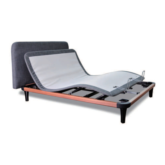
- Page 1 OWNER’S MANUAL Element Actual product appearance and functionality may vary from photographs, illustrations and descriptions included in this manual.
-
Page 2: Table Of Contents
table of contents Safety Precautions and Usage Statements ............... 1-4 Parts List . -
Page 3: Safety Precautions And Usage Statements
safety precautions and usage statements Attention: Important Safety Disclaimers Read all instructions before using your adjustable base. Save these instructions. WARNING void the electrical portion of your warranty. Always unplug the base from the electrical outlet before servicing any WARNING part of the base. - Page 4 TOLERANCE All Ergomotion adjustable foundations, depending on make and model, are Ergomotion adjustable bed bases are designed solely for in-home use. This base was designed and manufactured to perform and function within designated quality not designed as a hospital bed and is not designed to meet hospital standards. Do not use this base with TENT TYPE oxygen therapy equipment or near explosive gases.
- Page 5 safety precautions and usage statements To prolong the life of your fabric, protect from direct sunlight whenever possible. For spot cleaning, wipe area with a light damp sponge or vacuum with a soft brush translates to a tolerance of up to ¾”. attachment to remove particles.
- Page 6 safety precautions and usage statements Plug your adjustable base into a power surge protector. Evenly distribute weight when sleeping in a split setup (uneven distribution of weight can cause the base to lift unevenly). FCC Compliance: Call Customer Service for any technical issues. Do not try to force the base down (this can damage the motors or frame).
-
Page 7: Parts List
parts list Before discarding the packing materials, ensure all the parts are accounted for. All electronics and components that need to be installed are located in boxes under the base or attached to the frame. Wireless Remote Control and 3 AAA Batteries Mattress Retainer Bar Power Cord Power Supply... -
Page 8: Base And Remote Overview
base and remote overview Underbed light on/o Head Motor Head Massage Foot Massage Massage turn Foot Motor Lifts and lowers Lifts and lowers Massage foot portion of the head portion of the base base Powerdown Flat preset button Preset Position Button Control Box ZERO G preset button... -
Page 9: Quick Reference Guide
quick reference guide Not to scale. For illustration purposes only. Read all instructions before beginning installation. CONTROL BOX OVERVIEW ELECTRONICS OVERVIEW Connect with head and foot massage Power Cor d Foot Motor Input Power Suppl y Power Cor d Reset/Pairing Pairing Power Power Down... -
Page 10: Installation Guide
installation guide Always use two people when setting up the base. STEP 1 STEP 4 Place the bed base box in a desired location with the top of the To sync two bases see detailed installation box facing up. instructions on page 13. Remove the binding straps and packing materials, making sure not Locate the Power down Box and install (2) 9 Volt batteries to puncture the box with any sharp objects. - Page 11 installation guide STEP 7 STEP 10 Install mattress retainer bars by inserting both ends of mattress retainers bar into holes on the platform and laying the bars rest frame on its side, excessive pressure may damage the legs. down with curved side facing up. STEP 8 Plug the power cord into a power source.
-
Page 12: Remote Control
remote control Remote Control arrives paired to the adjustable base. Three (3) AAA batteries are required to operate the remote. ONE TOUCH BUTTONS ADJUST Foot Position Head Position Adjustments Adjustments Use to raise and Use to raise and lower the foot lower the head section of your section of your... - Page 13 remote control Remote Pairing The original remote that comes in the box is already paired to the adjustable base. No further action is required. In the event that the remote is not paired with the base, follow the steps below. STEP 1 STEP 3 Locate the Power Down Box and...
-
Page 14: Bluetooth® Remote Control Setup
bluetooth® remote control setup (optional) To operate the base from a smart device, the “Ergo Slim” application must be downloaded to the desired smart device from the App Store (Apple) or Google Play Store (Android). STEP 3 STEP 1 Plug the bed into power source. Select desired base. -
Page 15: Syncing Two Bases
syncing two bases (optional) A Sync Cord is included with the base. Not available on Queen, Full or Full-Long size bases. The Sync Cord connects the two control boxes to a single remote for the synchronization of two bases. STEP 1 Unplug bases from power source. -
Page 16: Power-Down Box
emergency powerdown box Store the power down box in a convenient location for emergency use. Two (2) 9 Volt batteries are required to operate the power down feature and are NOT included. OVERVIEW For emergency use only, in case of a power outage. In the event that the base is stuck in an articulated position during a power outage, the Power Down Box will return the base to a FLAT position. -
Page 17: Connecting Straps
connecting strap (optional) Connecting straps are secured to the base frame upon delivery. Legs are required for the installation of the connecting straps. STEP 1 STEP 2 With the bases in their desired location, slightly loosen both legs Slide side (a) of the connecting strap onto leg bolt. Swing the strap and connect side (b) to the leg bolt. -
Page 18: Headboard Brackets
headboard bracket installation guide (optional) STEP 1 STEP 4 Make sure the bottom Complete steps 3-6 for other side of the base is facing up. of the base. Accessories for installation: 2 ower bolts, 1 short bolt, 1 nut STEP 2 STEP 5 Align the headboard with the bracket, and slide the headboard on Lay the bracket at on the corner of... -
Page 19: Troubleshooting
troubleshooting Check under the bed base to verify that the wired connections are secure and that there are no cords or bedding obstructing the movement of the base. Check to ensure the green LED light is illuminated on the control box. If there is no light, verify that the input and power cords are properly connected. - Page 20 ERGOMOTION EU,UAB ©2017 Ergomotion Inc V001 _R06_04/2017 35006152 Didlaukio 80-96 Vilnius,8326,Lithuania salesEU@ergomotion.com contact number +37061386359 Serial Number:...
Need help?
Do you have a question about the Element and is the answer not in the manual?
Questions and answers