Table of Contents
Advertisement
Quick Links
Technical Support and E-Warranty Certificate www.vevor.com/support
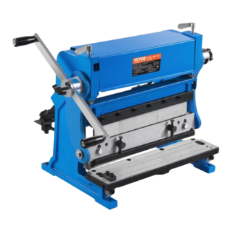
THE SHEAR / BRAKE / ROLL
OPERATION MANUAL
MODEL:3 IN 1/305
We continue to be committed to provide you tools with competitive price.
"Save Half", "Half Price" or any other similar expressions used by us only represents an
estimate of savings you might benefit from buying certain tools with us compared to the major
top brands and doses not necessarily mean to cover all categories of tools offered by us. You
are kindly reminded to verify carefully when you are placing an order with us if you are
actually saving half in comparison with the top major brands.
Advertisement
Table of Contents

Related Manuals for VEVOR 3 IN 1/305


Summary of Contents for VEVOR 3 IN 1/305
- Page 1 Technical Support and E-Warranty Certificate www.vevor.com/support THE SHEAR / BRAKE / ROLL OPERATION MANUAL MODEL:3 IN 1/305 We continue to be committed to provide you tools with competitive price. "Save Half", "Half Price" or any other similar expressions used by us only represents an estimate of savings you might benefit from buying certain tools with us compared to the major top brands and doses not necessarily mean to cover all categories of tools offered by us.
- Page 3 This is the original instruction, please read all manual instructions carefully before operating. VEVOR reserves a clear interpretation of our user manual. The appearance of the product shall be subject to the product you received. Please forgive us that we won't inform you again if there are any technology or software updates on our product.
-
Page 4: Specifications
Warning-To reduce the risk of injury, user must read instructions manual carefully. SPECIFICATIONS Model.....................3 in 1/305 Effective Width..........305mm (12 inches) Maximum Shearing Thickness…............1mm (20 gauge) Bending Thickness……............1mm (20 gauge) BendingAngle....90° Rolling thickness……...…1mm (20 gauge) Roll Diameter……............….45mm (1-1/2 inches) Standard accessories... -
Page 5: Safety Rules
Warning The warnings, cautions and instructions discussed in this instructions or situations that could occur. It must be understood by the operator that common sense and caution are factors that cannot be built into this product, but must be supplied by the operator. SAVE THESE INSTRUCTIONS Thank you for purchasing 12-inch Shear/Brake/Roll machine. - Page 6 protection should be used in appropriate conditions. 6. Wear proper apparel. Loose clothing, gloves, neckties, rings, bracelets, or other jewelry may present a potential hazard when operating this machine. Please keep all apparel clear of the machine. 7. Don’t overreach. Keep proper footing and balance always when operating this product.
-
Page 7: Setup And Assembly
SET-UP AND ASSEMBLY Floor Diagrams Figure 1 – hole centers for Shear, Brake and Roll Assembly Tools required for setup and assembly:5, 6mm hex keys (“Allen wrenches”)16mm open end wrench. 1. Take out machine and spare parts from box. 2. Carefully clean all rust protected surfaces with a mild solvent or kerosene and a soft rag. - Page 8 6. Remove one handle (A, Figure 2) from each operating handle assembly, using 6mm hex key. Figure 2 7. Loosen lock bolt (C, Figure 2). 8. Slide bar (B) into hub and tighten lock bolt (C) to secure. 9. Re-install handle (A). 10.
- Page 9 PRESS BRAKE SET-UP Do not bend material larger than 12” 20-gauge mild steel. Failure to comply may cause serious injury and/or damage to the machine. To set up for bending: 1. Place a strip of wood (F, Figure 5) on bottom die, the full length of die. 2.
- Page 10 through trial and error, or by consulting a machinist’s handbook.) 9. Rest workpiece on v-block (lower die)so that the scribed line is aligned with the tips of upper die(s). 10. Hold workpiece steady and use operating handle to make bend. To adjust brake beam (G, Figure 6) for90°...
- Page 11 The end of workpiece should be against guide plate. 3. Operate handle to begin shearing cut. Shearing action progresses from right to left. NOTE: 1. To prevent distortion when notching, “snap” the handle to facilitate piercing. 2. Do not reach behind the machine to catch the cut-off piece. A large cut-off piece should be allowed to drop onto a special table designed to catch pieces that are bigger than the workbench.
- Page 12 3. Rotate adjustment screws (M, Figure 8)to shift table and change the gap between blades. Do not allow the blades to overlap. 4. If the shear cuts the paper on the ends, but not the center, slightly turn screw (N,Figure 9) clockwise until paper is cut the entire length. Figure 8 5.
- Page 13 2. Raise upper blade to highest position. 3. Remove 4 screws (P, Figure 10) and carefully remove blade. 4. Rotate or replace blade and re-install screws (P). 5. Re-install hold-down. When blade is in highest position, the gap between the hold-down and the table should be within1/4. Adjust to this position by turning the wo screws (O, Figure 10) as needed.
- Page 14 approximate length of material needed. Cut several pieces of material to this length for a forming test run. Material may have to be lengthened or shortened depending on results of test run. TIP: If it doesn’t interfere with the proposed final shape or design, a slight bend made with the press brake on the leading edge will simplify the initial rolling process, by allowing the leading edge to slip more easily over the idle roll.
- Page 15 6. Run workpiece through the machine using the handles. If workpiece is large, make sure it receives proper support as it exits the machine. 7. Make further passes of workpiece, raising the idle roll incrementally before each pass, until desired radius is achieved. No exact formula can be followed when making roll adjustments because material “spring-back”...
- Page 16 Flat Rolling Softer metals (copper, aluminum, etc.)can be processed through the slip roll machine to straighten, flatten, or reduce their thickness. Simply adjust the upper press roll for thickness, lower idle roll all the way down, and feed workpiece through (Figure 13). NOTE: The idle roll will not descend completely out of the path of the workpiece;...
- Page 17 adjustments. Forming a Tube 1. Adjust upper press roll as needed for workpiece thickness. 2. Feed workpiece into machine. As it nears the end (a, Figure 15), stop and reverse direction (b, Figure 15). 3. Make further passes if needed, along with incremental idle roll adjustments.
- Page 18 of oil to them. 3. Lightly brush multi-purpose grease onto the gears at the end of the rollers (B, Figure 16). Turn operating handle to distribute the grease. 4.Keep other exposed areas clean and lightly coated with oil, such as the shear blades, table and upper dies.
- Page 19 Trouble Probable Cause Remedy SHEAR Adjust gap to accommodate Incorrect blade gap. thicker material. Material won’t cut. Machine capacity exceeded. Use materials within capacity. Unequal blade gap. Make blade gap equal. Maintain consistent guides Not contacting table guides. contact. Blade is bowed. Remove bow.
-
Page 20: Parts List
PARTS LIST PART PART DESCRIPTION Q'TY DESCRIPTION Q'TY Left frame Support rod Work surface Guide block Cross beam Backstop Cranking arm Adjustment bar Right frame Shears blade Shear frame Rear roll Bushing cover Screw Press plate bracket Handle Spring Positioning bolt Press plate Bushing Lower braking die... -
Page 21: Part Description
PART DESCRIPTION Q'TY PART DESCRIPTION Q'TY Taper pin Screw M6X20 Handle Screw M8X20 Screw M6x10 Knob Screw M8x35 Bolt M6X45 Washer 8 Round pin Bolt M10x40 Screw M6X10 Bolt M8x20 Screw M6X10 Washer 8 Screw M8X20 Nut M8 Stand type A (Optional) Bolt M10X16 Stand type B (Optional) Screw M8X25... - Page 22 Made In China - 20 -...
- Page 24 Technical Support and E-Warranty Certificate www.vevor.com/support...
Need help?
Do you have a question about the 3 IN 1/305 and is the answer not in the manual?
Questions and answers