
Subscribe to Our Youtube Channel
Related Manuals for Ruijie Reyee RG-RAP52-OD


Summary of Contents for Ruijie Reyee RG-RAP52-OD
- Page 1 Ruijie Reyee RG-RAP52-OD Access Point Hardware Installation and Reference Guide Document Version: V1.0 Date: 2023-11-16 Copyright © 2023 Ruijie Networks...
- Page 2 Except for the agreement in the contract, Ruijie Networks makes no explicit or implicit statements or warranties with respect to the content of this document.
-
Page 3: Preface
Preface Audience This document is intended for: Network engineers Technical support and servicing engineers Network administrators Technical Support Official Website of Ruijie Reyee: https://www.ruijienetworks.com/products/reyee Technical Support Website: https://www.ruijienetworks.com/support Case Portal: https://caseportal.ruijienetworks.com Community: https://community.ruijienetworks.com ... - Page 4 Caution An alert that calls attention to essential information that if not understood or followed can result in function failure or performance degradation. Note An alert that contains additional or supplementary information that if not understood or followed will not lead to serious consequences. Specification An alert that contains a description of product or version support.
-
Page 5: Table Of Contents
Contents Preface ..............................I 1 Product Overview ..........................1 1.1 Package Contents ........................1 1.2 Product Appearance ........................2 1.2.2 Front Panel ........................2 1.2.3 Back Panel ........................3 1.3 Technical Specifications ......................4 1.4 Power Supply Technical Specifications ..................6 1.5 Cooling ............................ - Page 6 3 Installing the AP ..........................11 3.1 Installation Flowchart ....................... 11 3.2 Before You Begin ........................11 3.3 Precautions ..........................12 3.4 Installing the AP ........................12 3.4.1 Installing the Antenna ....................13 3.4.2 Connecting the Ethernet Cable ................... 14 3.4.3 Installing the AP ......................
- Page 7 7 Appendixes ............................ 25 7.1 Connectors and Media ......................25 7.2 Cabling Recommendations ..................... 27 7.2.1 Requirements for Cable Bend Radius ................. 27 7.2.2 Precautions for Bundling up Cables ................27...
-
Page 8: Product Overview
Hardware Installation and Reference Guide Product Overview Product Overview Package Contents Table 1-1 Package Contents Item Quantity RG-RAP52-OD Access Point Antenna Band Clamp Mounting Bracket Screw Kit (Containing Two 3.5 mm × 25 mm Expansion Screws and Two Wall Anchors) Warranty Card Quick Installation Guide Note... -
Page 9: Product Appearance
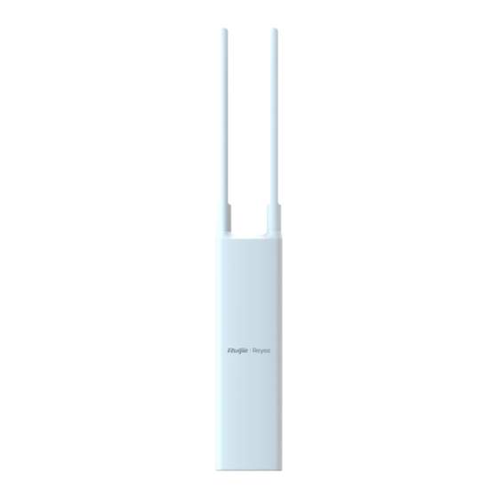
Hardware Installation and Reference Guide Product Overview Product Appearance Figure 1-1 Appearance of the RG-RAP52-OD Access Point 1.2.2 Front Panel Figure 1-2 Front Panel of the RG-RAP52-OD Access Point... -
Page 10: Back Panel
Hardware Installation and Reference Guide Product Overview 1.2.3 Back Panel Figure 1-3 Back Panel of the RG-RAP52-OD Access Point Table 1-2 LEDs Mark Status Description Solid blue The device is operating normally. The device is NOT receiving power. Fast blinking The device is starting up. -
Page 11: Technical Specifications
Hardware Installation and Reference Guide Product Overview The device is resetting. The device is upgrading. The device is recovering. Blinking twice Caution Do not power off the device when the LED is in this state. Table 1-3 Ports and Buttons Mark Item Description... - Page 12 Hardware Installation and Reference Guide Product Overview 5 GHz: dual-stream , 2 × 2 MIMO 2.4 GHz: 400 Mbps Max. Wi-Fi Speed 5 GHz: 867 Mbps Combined: 1267 Mbps OFDM: BPSK@6/9 Mbps, QPSK@12/18 Mbps, 16QAM@24 Mbps, 64QAM@48/54 Mbps Modulation Mode DSSS: DBPSK@1 Mbps, DQPSK@2 Mbps, CCK@5.5/11 Mbps MIMO-OFDM: BPSK, QPSK, 16QAM, 64QAM, 256QAM, OFDMA 11b/g: –92 dBm (1 Mbps), –90 dBm (5.5 Mbps), –88 dBm...
-
Page 13: Power Supply Technical Specifications
The RG-RAP52-OD access point supports IEEE 802.3af standard PoE power supply and 24 V non-standard PoE power supply. When using a 24 V non-standard PoE adapter for power supply, use the non-standard PoE adapter approved by Ruijie Reyee. You are advised to purchase the adapter from us... -
Page 14: Cooling
Hardware Installation and Reference Guide Product Overview to ensure compatibility and optimal performance with our product. Warning Ensure that the pinouts of the network cable are (pins 4, 5, 7, 8). When using a standard PoE power source for power supply, connect one end of the Ethernet cable to the LAN/PoE port of the device, and the other end to a PoE-enabled switch port or a PoE power supply. -
Page 15: Preparing For Installation
Hardware Installation and Reference Guide Preparing for Installation Preparing for Installation Safety Precautions Note To prevent device damage and physical injury, please read the safety precautions carefully in this chapter. The following safety precautions do not cover all possible hazardous situations. 2.1.1 Installation Safety ... -
Page 16: Installation Environment Requirements
Hardware Installation and Reference Guide Preparing for Installation Direct or indirect contact with a wet object (or your finger) on the high voltage and power line can be fatal. Please observe local regulations and specifications when performing electrical operations. Relevant operators must be qualified. -
Page 17: Waterproofing
Hardware Installation and Reference Guide Preparing for Installation Low relative humidity can dry and shrink insulation sheets and cause static electricity that can damage the circuitry. High temperatures greatly reduce device reliability and shorten service life. 2.2.3 Waterproofing The Ethernet cable must be pressed into the silicone pad before being connected to the Ethernet port on the device. -
Page 18: Installing The Ap
Hardware Installation and Reference Guide Installing the AP Installing the AP The RG-RAP52-OD access point must be fixed outdoors. Caution Before installing the AP, make sure you have carefully read the requirements described in Chapter 2 and the requirements are all met. Installation Flowchart Start Prepare for installation... -
Page 19: Precautions
Hardware Installation and Reference Guide Installing the AP The power supply and required current are available in the installation site. The selected power supply modules meet the system power requirements. The installation site meets the cabling requirements of the AP. ... -
Page 20: Installing The Antenna
Hardware Installation and Reference Guide Installing the AP 3.4.1 Installing the Antenna (1) Remove the antennas from the packaging and attach them to the antenna connectors on the AP. Tighten the antennas in a clockwise direction to securely fasten them in place. (2) Verify that the antennas are properly tightened. -
Page 21: Connecting The Ethernet Cable
Hardware Installation and Reference Guide Installing the AP 3.4.2 Connecting the Ethernet Cable Caution Ensure that the RJ45 connector of the Ethernet cable is properly connected to the AP. Incorrect connection of the RJ45 connector may result in abnormal network connection. When removing the Ethernet cable, first pull it out from the waterproof silicone slot, and then disconnect the RJ45 connector from the AP. - Page 22 Hardware Installation and Reference Guide Installing the AP (3) Fully insert the Ethernet cable into the opening of the silicone pad, leaving about 5 cm from the RJ45 connector. (4) Insert the RJ45 connector into the LAN/PoE port on the device, and then put the silicone pad back into the slot on the device.
-
Page 23: Installing The Ap
Hardware Installation and Reference Guide Installing the AP 3.4.3 Installing the AP Warning The installation site should be free from water flooding, seepage, dripping, or condensation. When installing this device, ensure that the antenna end is facing upwards and the device is mounted perpendicular to the ground. - Page 24 Hardware Installation and Reference Guide Installing the AP (2) Attach the mounting bracket to the wall with two expansion screws (3.5 mm × 25 mm). Caution When installing the mounting bracket, ensure that the opening of the bracket is facing upwards.
- Page 25 Hardware Installation and Reference Guide Installing the AP (3) Push and slide the AP downwards to lock it in place. The installation is complete.
-
Page 26: Bundling Cables
Hardware Installation and Reference Guide Installing the AP 2. Mounting the AP on a Vertical Pole (1) Thread the band clamp through the hole on the back panel of the AP. (2) Wrap the band clamps around the pole and pull it tight. The installation is complete. Bundling Cables Caution ... - Page 27 Hardware Installation and Reference Guide Installing the AP (2) Checking Cable Connections Verify that the UTP/STP cable matches with the port type. Verify that cables are properly bundled. (3) Checking Power Supply Verify that the power cord is properly connected and compliant with safety requirements. ...
-
Page 28: Debugging
Hardware Installation and Reference Guide Debugging Debugging Setting up Configuration Environment Use a 24 V non-standard PoE adapter or PoE power source to supply power to the device. Before powering on the device using a 24 V non-standard PoE adapter or PoE power source, verify that the power cord is properly connected, and that the configuration environment meets the safety requirements. -
Page 29: Monitoring And Maintenance
Hardware Installation and Reference Guide Monitoring and Maintenance Monitoring and Maintenance Monitoring When RG-RAP52-OD is operating, you can monitor its status by observing the LEDs. Maintenance If the hardware is faulty, please contact Ruijie technical support for assistance. -
Page 30: Troubleshooting
Check whether the power supply is properly connected. Check whether the LED is normal. Check whether cables are properly connected with ports. Contact Ruijie technical support to check whether hardware faults exist. Finish Common Faults The status LED is off after the AP is powered on. - Page 31 Hardware Installation and Reference Guide Troubleshooting ○ Verify that the AP is properly powered. ○ Verify that the Ethernet port or the optical port is correctly connected. ○ Verify that the AP is correctly configured. ○ Move the client device to adjust the distance between the client and the AP.
- Page 32 Hardware Installation and Reference Guide Appendixes Appendixes Connectors and Media 1000BASE-T/100BASE-TX/10BASE-T Port The 1000BASE-T/100BASE-TX/10BASE-T is a 10/100/1000 Mbps auto-negotiation port that supports auto MDI/MDIX Crossover. Compliant with IEEE 802.3ab, 1000BASE-T requires Category 5e 100-ohm UTP or STP (recommended) with a maximum distance of 100 meters (328 feet). The 1000BASE-T port requires all four pairs of wires to be connected for data transmission.
- Page 33 Hardware Installation and Reference Guide Appendixes Socket Plug Output Transmit Data- Input Receive Data- 4, 5, 7, 8 Not Used Not Used The following figure shows feasible connections of the straight-through and crossover twisted pairs for a 100BASE-TX/10BASE-T port. Figure 7-2 100BASE-TX/10BASE-T Twisted Pair Connections...
- Page 34 Hardware Installation and Reference Guide Appendixes Cabling Recommendations During installation, route cable bundles upward or downward along the sides of the rack depending on the actual situation in the equipment room. All cable connectors used for transit should be placed at the bottom of the cabinet rather than be exposed outside of the cabinet. Power cords are routed beside the cabinet, and top cabling or bottom cabling is adopted according to the actual situation in the equipment room, such as the positions of the DC power distribution box, AC socket, or lightning protection box.
- Page 35 Hardware Installation and Reference Guide Appendixes The cable management brackets and cabling troughs inside and outside the cabinet should be smooth without sharp corners. The metal hole traversed by cables should have a smooth and fully rounding surface or an insulated lining.
- Page 36 Hardware Installation and Reference Guide Appendixes moving part is installed, the remaining cable part should not touch heat sources, sharp corners, or sharp edges. If heat sources cannot be avoided, high-temperature cables should be used. If heat sources cannot be avoided, high-temperature cables should be used. ...
Need help?
Do you have a question about the Reyee RG-RAP52-OD and is the answer not in the manual?
Questions and answers