Table of Contents
Advertisement
Quick Links
Advertisement
Table of Contents
Troubleshooting

Related Manuals for Supermicro SuperServer SYS-510T-WTR-EU


Summary of Contents for Supermicro SuperServer SYS-510T-WTR-EU
- Page 1 SuperServer ® SYS-510T-WTR SYS-510T-WTR-EU USER’S MANUAL Revision 1.0b...
- Page 2 State of California, USA. The State of California, County of Santa Clara shall be the exclusive venue for the resolution of any such disputes. Supermicro's total liability for all claims will not exceed the price paid for the hardware product.
- Page 3 If you have any questions, please contact our support team at: support@supermicro.com This manual may be periodically updated without notice. Please check the Supermicro website for possible updates to the manual revision level. Secure Data Deletion A secure data deletion tool designed to fully erase all data from storage devices can be found on our website: https://www.supermicro.com/about/policies/disclaimer.cfm?url=/wdl/utility/...
-
Page 4: Table Of Contents
Preface Contents Contacting Supermicro ......................8 Chapter 1 Introduction 1.1 Overview ..........................9 1.2 System Features ........................10 Front View .........................10 Control Panel .........................11 Rear View ..........................12 1.3 System Architecture ......................14 Main Components ......................14 System Block Diagram ......................16 1.4 Motherboard Layout ......................17 Quick Reference Table ......................18 Chapter 2 Server Installation 2.1 Overview ..........................20... - Page 5 Preface Chapter 3 Maintenance and Component Installation 3.1 Removing Power .......................27 3.2 Accessing the System ......................28 Removing the Top Cover ....................28 3.3 Static-Sensitive Devices .....................29 Precautions ........................29 3.4 Processor and Heatsink Installation ...................30 3.5 Memory ..........................35 Memory Support ........................35 Memory Installation Sequence ..................35 General Memory Population Requirements ..............35 General Guidelines for Optimizing Memory Performance ..........36 DIMM Installation ......................37...
- Page 6 Preface 4.4 Jumpers ..........................60 4.5 LED Indicators ........................62 4.6 Storage Ports ........................64 Chapter 5 Software 5.1 Microsoft Windows OS Installation ..................65 5.2 Driver Installation ........................67 5.3 SuperDoctor 5 ........................68 ® 5.4 IPMI ............................69 BMC ADMIN User Password ...................69 Chapter 6 Optional Components 6.1 Storage Drive Options ......................70 6.2 TPM Security Module ......................70 Chapter 7 Troubleshooting and Support...
- Page 7 7.10 Reporting an Issue ......................84 Technical Support Procedures ..................84 Returning Merchandise for Service ...................84 Vendor Support Filing System ..................85 7.11 Feedback ..........................85 7.12 Contacting Supermicro ......................86 Appendix A Standardized Warning Statements for AC Systems Appendix B System Specifications BSMI/RoHS ..........................110...
-
Page 8: Contacting Supermicro
San Jose, CA 95131 U.S.A. Tel: +1 (408) 503-8000 Fax: +1 (408) 503-8008 Email: marketing@supermicro.com (General Information) Sales-USA@supermicro.com (Sales Inquiries) Government_Sales-USA@supermicro.com (Gov. Sales Inquiries) support@supermicro.com (Technical Support) RMA@supermicro.com (RMA Support) Webmaster@supermicro.com (Webmaster) Website: www.supermicro.com Europe Address: Super Micro Computer B.V. -
Page 9: Chapter 1 Introduction
Level) Form Factor 1U Rackmount 1.7 x 17.2 x 25.6in. / 43 x 437 x 650mm (HxWxD) Notes: A Quick Reference Guide can be found on the product page of the Supermicro ® website. The following safety models associated with the SYS-510T-WTR/WTR-EU have been certified... -
Page 10: System Features
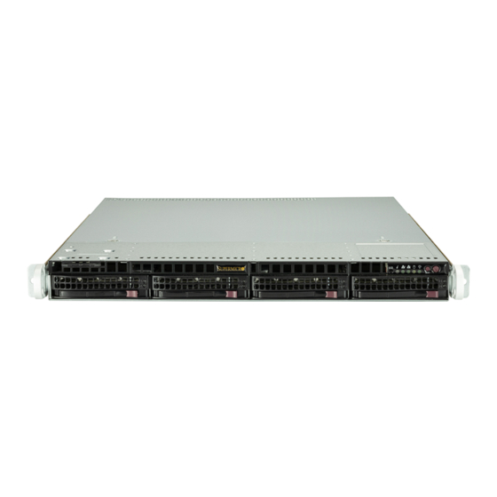
Chapter 1: Introduction 1.2 System Features The following views of the system display the main features. Refer to Appendix B for additional specifications. Front View Control Panel Service/Asset Tag with BMC Password Figure 1-1. Front View System Features: Front Feature Description Control Panel One control panel (see... -
Page 11: Control Panel
Chapter 1: Introduction Control Panel Information LED Reset Power NIC LED U I D B u t t o n / BMC Reset Power LED NIC LED Figure 1-2. Control Panel Control Panel Features Feature Description UID button/ The unit identification (UID) button turns on or off the blue light function of the Information BMC reset LED. -
Page 12: Rear View
Chapter 1: Introduction Rear View LAN Ports USB Ports PSW2 COM Port VGA Port PSW1 IPMI LAN Port Figure 1-3. System: Rear View System Features: Rear Feature Description Power Supplies Two redundant power supply modules, PWS1 on the right, PWS2 on the left COM Port One COM port IPMI LAN Port... - Page 13 Chapter 1: Introduction Power Supply Indicators Power Supply Condition Green LED Amber LED No AC Power to Power Supply Power Supply critical events causing a shutdown/ failure/ OCP/ OVP/ Fan Fail/ Amber LED OTP/ UVP Power Supply Warning Events Where the power supply continues to operate;...
-
Page 14: System Architecture
Chapter 1: Introduction 1.3 System Architecture This section covers the locations of the system's electrical components, a system block diagram, and a motherboard layout with the connectors and jumpers called out. Main Components P o w e r S u p p l y Modules DIMM Slots System Fans... - Page 15 Chapter 1: Introduction System Features: Top Feature Description Power Supply Dual redundant modules, PWS-504P-1R2 DIMM slots Four DIMM memory slots Single Intel® Xeon® E-2300, 10th Generation Pentium in an LGA1200 (H5) socket with Processors heatsinks, SNK-P0049P System Fans Four 4-cm counter-rotating PWM fans Pull Tag Pull tag with serial number / BMC ADMIN password Backplane...
-
Page 16: System Block Diagram
Chapter 1: Introduction System Block Diagram The block diagram below shows the connections and relationships between the subsystems and major components of the overall system. IMVP 8 6 PHASE for Vcore 2 PHASE for VGT Skt-H5 PCIe Gen4 x16 SXB1 PCIe 4.0 x16 #0-15 LGA1200... -
Page 17: Motherboard Layout
Chapter 1: Introduction 1.4 Motherboard Layout Below is a layout of the X12STW-TF motherboard with jumper, connector, and LED locations shown. See the table on the following page for descriptions. For detailed descriptions, pinout information, and jumper settings, refer to Chapter 4 or the Motherboard Manual. -
Page 18: Quick Reference Table
Chapter 1: Introduction Quick Reference Table Jumper Description Default Setting JBT1 CMOS clear Open (Normal) Pins 1-2 (JSEN1) JSEN1/JIPMB1 Pins 2-3 (JIPMB1) JPG1 VGA Enable/Disable Pins 1-2 (Enabled) JPL1 LAN1 Enable/Disable (LAN I210) Pins 1-2 (Enabled) JPL2 LAN2 Enable/Disable (LAN I210) Pins 1-2 (Enabled) JPME2 Manufacturing mode select... - Page 19 Chapter 1: Introduction Connector Description JSXB1A, JSXB1B, JSXB1C SMC-Proprietary WIO_L (Left) PCIe 4.0 x16 add-on card slots JSXB2 SMC-Proprietary WIO_R (Right) PCIe 3.0 x4 add-on card slot JTPM1 Trusted Platform Module (TPM) header JUIDB1 Unit Identifier (UID) button JVGA VGA connector M.2-C M.2 PCIe 4.0 x4 slot (2280/22110) M.2-P...
-
Page 20: Chapter 2 Server Installation
Chapter 2: Server Installation Chapter 2 Server Installation 2.1 Overview This chapter provides advice and instructions for mounting your system in a server rack. If your system is not already fully integrated with processors, system memory, etc., refer to Chapter 3 for details on installing those specific components. -
Page 21: Rack Precautions
Chapter 2: Server Installation • This product is not suitable for use with visual display workplace devices according to §2 of the German Ordinance for Work with Visual Display Units. Rack Precautions • Ensure that the leveling jacks on the bottom of the rack are extended to the floor so that the full weight of the rack rests on them. -
Page 22: Airflow
Chapter 2: Server Installation Airflow Equipment should be mounted into a rack so that the amount of airflow required for safe operation is not compromised. Mechanical Loading Equipment should be mounted into a rack so that a hazardous condition does not arise due to uneven mechanical loading. -
Page 23: Installing The Rails
Chapter 2: Server Installation 2.4 Installing the Rails There are a variety of rack units on the market, which may require a slightly different assembly procedure. The following is a basic guideline for installing the system into a rack with the rack mounting hardware provided. -
Page 24: Installing The Outer Rails
Chapter 2: Server Installation Installing the Outer Rails Begin by measuring the distance from the front rail to the rear rail of the rack. Attach a short bracket to the front side of the right outer rail and a long bracket to the rear side of the right outer rail. -
Page 25: Installing The Server Into A Rack
Chapter 2: Server Installation 2.5 Installing the Server into a Rack Installing to a Standard Rack You should now have rails attached to both the chassis and the rack. The next step is to install the server into the rack. 1. -
Page 26: Installing To A Telco Rack
Chapter 2: Server Installation Installing to a Telco Rack To install the SuperServer SYS-510T-WTR/WTR-EU into a Telco (or “open”) type rack, use two L-shaped brackets on either side of the chassis (four total). 1. First, determine how far the server will extend out from the front of the rack. The chassis should be positioned so that the weight is balanced between front and back. -
Page 27: Chapter 3 Maintenance And Component Installation
Chapter 3: Maintenance and Component Installation Chapter 3 Maintenance and Component Installation This chapter provides instructions on installing and replacing main system components. To prevent compatibility issues, only use components that match the specifications and/or part numbers given. Installation or replacement of most components requires that power first be removed from the system. -
Page 28: Accessing The System
Chapter 3: Maintenance and Component Installation 3.2 Accessing the System The CSE-815T chassis features a removable top cover, which allows easy access to the inside of the chassis. Removing the Top Cover 1. Begin by removing power from the system as described in Section 3.1. 2. -
Page 29: Static-Sensitive Devices
Chapter 3: Maintenance and Component Installation 3.3 Static-Sensitive Devices Electrostatic Discharge (ESD) can damage electronic com ponents. To avoid damaging your motherboard, it is important to handle it very carefully. The following measures are generally sufficient to protect the system PCBs from ESD. Precautions •... -
Page 30: Processor And Heatsink Installation
• Thermal grease is pre-applied on new heatsinks. No additional thermal grease is needed. • Refer to the Supermicro website (https://www.supermicro.com/en) for updates on proces- ® sor and memory support. • All graphics in this manual are for illustration only. Your components may look different. - Page 31 Chapter 3: Maintenance and Component Installation Installing the Processor(s) Begin by removing power from the system as described in Section 3.1. 1. Remove the cover plate that protects the CPU#1 socket: press the load lever to release the load plate, which covers the CPU socket, from its locked position. Load Plate Load Plate Load Lever...
- Page 32 Chapter 3: Maintenance and Component Installation Figure 3-3. Inspecting the Processor Installation 4. Once aligned, carefully place the processor into the socket. Do not drop the processor on the socket, move or rub the processor against the socket or against any socket pins, which may damage the components.
- Page 33 Chapter 3: Maintenance and Component Installation Installing a Heatsink A passive type heatsink is used on the X12STW-TF. Note: Do not apply any thermal grease to the heatsink or the CPU die; the required amount has already been applied. 1. Place the heatsink on top of the CPU so that the four mounting holes are aligned with those on the heatsink retention mechanism.
- Page 34 Chapter 3: Maintenance and Component Installation Removing a Heatsink We do not recommend removing the heatsink. If necessary, please follow the instructions below to prevent damage to the CPU or the CPU socket. 1. Unscrew and remove the heatsink screws from the motherboard in the sequence as show in the figure above.
-
Page 35: Memory
3200MHz in four memory slots. Refer to the tables below for the recommended DIMM population order and additional memory information. For validated memory, use our Product Resources page. Check the Supermicro website for possible updates to memory support. ® Memory Installation Sequence Memory for this motherboard is populated using the "Fill First"... -
Page 36: General Guidelines For Optimizing Memory Performance
Chapter 3: Maintenance and Component Installation Max Memory 4 Gb DRAM 8 Gb DRAM 16 Gb DRAM Possible Technology Technology Technology Single Rank 16 GB 32 GB 64 GB UDIMM (4 x 4 GB DIMMs) (4 x 8 GB DIMMs) (4 x 16 GB DIMMs) Dual Rank 32 GB... -
Page 37: Dimm Installation
Chapter 3: Maintenance and Component Installation DIMM Installation 1. Insert the desired number of DIMMs into the slots based on the recommended DIMM population tables shown above. 2. Push the release tabs on both ends of the DIMM slot outwards to unlock it. 3. -
Page 38: Motherboard Battery
Chapter 3: Maintenance and Component Installation 3.6 Motherboard Battery The motherboard uses non-volatile memory to retain system information when system power is removed. This memory is powered by a lithium battery residing on the motherboard. Replacing the Battery Begin by removing power from the system. -
Page 39: Cable Routing Diagrams
Chapter 3: Maintenance and Component Installation 3.7 Cable Routing Diagrams MiniSAS HD cable for onboard SATA and 3008/3108 Controller CBL-SAST-0699 (default) Slimline cable for 3808/3908 Controller CBL-SAST-1275A-100 (optional) Figure 3-7. Cable Routing Diagram... -
Page 40: Storage Drives
Chapter 3: Maintenance and Component Installation 3.8 Storage Drives The storage drives are mounted in tool-less drive carriers that simplify their removal from the chassis. These carriers also help promote proper airflow. For compatible storage drives, see the product page. Installing Drives Figure 3-8. -
Page 41: Installing M.2 Solid State Drives
Chapter 3: Maintenance and Component Installation Installing M.2 Solid State Drives The X12STW-TF motherboard has two M.2 slots (M.2-C and M.2-P). M.2 was formerly known as Next Generation Form Factor (NGFF) and serves to replace mini PCIe. M.2 allows for a variety of card sizes, increased functionality, and spatial efficiency. -
Page 42: System Cooling
Chapter 3: Maintenance and Component Installation 3.9 System Cooling Fans Up to six 4-cm counter-rotating fans provide the cooling for the system. Each fan unit is actually made up of two fans joined back-to-back, which rotate in opposite directions. This counter-rotating action generates exceptional airflow and is effective in dampening vibration levels. - Page 43 Chapter 3: Maintenance and Component Installation Figure 3-10. Replacing a System Fan Note: the figure above is intended to show fan location only. The serverboard may differ from that in the SYS-510T-WTR/WTR-EU.
-
Page 44: Air Shrouds
Chapter 3: Maintenance and Component Installation Air Shrouds Air shrouds concentrate airflow to maximize fan efficiency. The SYS-510T-WTR/WTR-EU includes one air shroud for each CPU. Figure 3-11. Installing Air Shroud for CPU DIMMs... -
Page 45: Expansion Cards
Chapter 3: Maintenance and Component Installation 3.10 Expansion Cards The SYS-510T-WTR/WTR-EU includes two riser cards to support the use of expansion (add- on) cards. Before following the procedure below to install expansion cards, first turn off and remove power from the system as described in section 3.1 then remove the top cover. Figure 3-12. -
Page 46: Power Supply
The SYS-510T-WTR/WTR-EU includes a redundant power supply, which allows the server to continue running when one power supply has been removed. Replacement units can be ordered directly from Supermicro. Replacing the Power Supply 1. Unplug the AC power cord from the failed power supply module (with the RED LED lit up). - Page 47 Chapter 3: Maintenance and Component Installation Release Tab Figure 3-13. Removing/Replacing a Power Supply Note: The figure above is intended to show the power supply locations only. The chassis and serverboard may differ from that found in the SYS-510T-WTR/WTR-EU.
-
Page 48: Bmc
Chapter 3: Maintenance and Component Installation 3.12 BMC The BMC can be reset using the button on the front control panel or on the chassis rear. • Reset—Press and hold the button. After six seconds, the LED blinks at 2 Hz. The BMC resets and the reset duration is ~250 ms. -
Page 49: Chapter 4 Motherboard Connections
Chapter 4: Motherboard Connections Chapter 4 Motherboard Connections This section describes the connections on the motherboard and provides pinout definitions. Note that depending on how the system is configured, not all connections are required. The LEDs on the motherboard are also described here. A motherboard layout indicating component locations may be found in Chapter 1. -
Page 50: Headers And Connectors
Chapter 4: Motherboard Connections 4.2 Headers and Connectors Fan Headers There are six 4-pin fan headers (FAN1 - FAN6) on the motherboard. All these 4-pin fan headers are backwards compatible with the traditional 3-pin fans. However, fan speed control is available for 4-pin fans only by Thermal Management via the BMC. Refer to the table below for pin definitions. - Page 51 Port 80 connection. Use this header to enhance system performance and data security. Refer to the table below for pin definitions. Please go to the following link for more information on the TPM: http://www.supermicro.com/manuals/other/TPM.pdf. Trusted Platform Module Header Pin Definitions...
- Page 52 Chapter 4: Motherboard Connections 4-pin BMC External I C Header/System Front Inlet Temperature Sensor JIPMB1 and JSEN1 share the same header. To switch between the two, set the jumper on JP1. See the JP1 table below for the jumper settings. A System Management Bus header for IPMI 2.0 is located at JIPMB1.
- Page 53 Chapter 4: Motherboard Connections Internal Speaker/Buzzer The Internal Speaker/Buzzer (SP1) is used to provide audible indications for various beep codes. Refer to the table below for pin definitions. Internal Buzzer Pin Definitions Pin# Definition Pos (+) Neg (-) Beep In...
-
Page 54: Control Panel
The front control panel header (JF1) contains header pins for various buttons and indicators that are normally located on a control panel at the front of the chassis. These connectors are designed specifically for use with Supermicro chassis. See the figure below for the ®... - Page 55 Chapter 4: Motherboard Connections Overheat (OH)/Fan Fail Connect an LED cable to pins 7 and 8 of the Front Control Panel to use the Overheat/Fan Fail LED connections. The LED on pin 8 provides warnings of overheating or fan failure. Refer to the tables below for pin definitions.
-
Page 56: Input/Output Ports
Chapter 4: Motherboard Connections NMI Button The non-maskable interrupt (NMI) button header is located on pins 19 and 20 of JF1. Refer to the table below for pin definitions. NMI Button Pin Definitions (JF1) Pins Definition Control Ground 4.3 Input/Output Ports I/O Ports The locations and descriptions of the various I/O ports are on the rear of the motherboard. - Page 57 Chapter 4: Motherboard Connections COM Port and Header The motherboard has one COM port (JCOM1) on the back panel and one COM header (JCOM2). LAN Ports Two 1GbE Ethernet (-F) or two 10GbE ports (-TF) (JLAN1/2) are located on the I/O back panel.
- Page 58 Chapter 4: Motherboard Connections Universal Serial Bus (USB) Ports There are two USB 2.0 ports (USB0/1) and two USB 3.2 Gen 1 ports (USB6/7) located on the back I/O panel. The motherboard also has two front access USB 2.0 headers (USB2/3, USB4/5) and one front access USB 3.2 Gen 1 header (USB9/10).
- Page 59 LED indicator. Note: UID can also be triggered via IPMI on the motherboard. For more information on IPMI, please refer to the IPMI User's Guide posted on our website: https://www.supermicro.com/ support/manuals/ UID Switch...
-
Page 60: Jumpers
Chapter 4: Motherboard Connections 4.4 Jumpers Explanation of Jumpers To modify the operation of the motherboard, jumpers can be used to choose between optional settings. Jumpers create shorts between two pins to change the function of the connector. Pin 1 is identified with a square solder pad on the printed circuit board. See the diagram below for an example of jumping pins 1 and 2. - Page 61 Chapter 4: Motherboard Connections Watch Dog Timer Watchdog (JWD1) is a system monitor that can reboot the system when a software application hangs. Close pins 1-2 to reset the system if an application hangs. Close pins 2-3 to generate a non-maskable interrupt (NMI) signal for the application that hangs. Refer to the table below for jumper settings.
-
Page 62: Led Indicators
Chapter 4: Motherboard Connections 4.5 LED Indicators LAN LEDs Two LAN ports (JLAN1 and JLAN2) are located on the I/O back panel of the motherboard. Each Ethernet LAN port has two LEDs. The green LED indicates activity, while the other Link LED may be green, amber, or off to indicate the speed of the connection. - Page 63 Chapter 4: Motherboard Connections Power Ready LED A Power Ready LED is located at LE6 on the motherboard. When this LED is green, all onboard power VRMs are normal. See the table below for more information. Power Ready LED Indicator LED Color Definition All onboard PWR VRMs...
-
Page 64: Storage Ports
These SATA ports support RAID 0, 1, 5, and 10. Note: For more information on the SATA HostRAID configuration, please refer to the Intel SATA HostRAID user's guide posted on our website at https://www.supermicro.com/support/ manuals/. M.2 Slot This motherboard has two M.2 slots (M.2-C and M.2-P). M.2 was formerly known as Next Generation Form Factor (NGFF) and serves to replace mini PCIe. -
Page 65: Chapter 5 Software
USB flash or media drive, perhaps using a USB flash or media drive, or the IPMI KVM console. 2. Retrieve the proper RST/RSTe driver. Go to the Supermicro® web page for your motherboard and click on "Download the Latest Drivers and Utilities", select the proper driver, and copy it to a USB flash drive. - Page 66 Chapter 5: Software 4. During Windows Setup, continue to the dialog where you select the drives on which to install Windows. If the disk you want to use is not listed, click on “Load driver” link at the bottom left corner. Figure 5-2.
-
Page 67: Driver Installation
Chapter 5: Software 5.2 Driver Installation The Supermicro website contains drivers and utilities for your system at https:// www. supermicro. com/wdl/driver. Some of these must be installed, such as the chipset driver. After accessing the website, go into the CDR_Images (in the parent directory of the above link) and locate the ISO file for your motherboard. -
Page 68: Superdoctor ® 5
5.3 SuperDoctor ® The Supermicro® SuperDoctor 5 is a program that functions in a command-line or web-based interface for Windows and Linux operating systems. The program monitors such system health information as CPU temperature, system voltages, system power consumption, fan speed, and provides alerts via email or Simple Network Management Protocol (SNMP). -
Page 69: Ipmi
This can be found on a sticker on the chassis and a sticker on the motherboard. The sticker also displays the BMC MAC address. If necessary, the password can be reset using the Supermicro® IPMICFG tool. Figure 5-5. BMC Password Label The sticker can be found on the pull-out service tag at the front of the chassis. -
Page 70: Chapter 6 Optional Components
It enables the motherboard to deny access if the TPM associated with the hard drive is not installed in the system. Details and installation procedures are at: http://www.supermicro.com/manuals/other/TPM.pdf. • AOM-TPM-9670V •... -
Page 71: Chapter 7 Troubleshooting And Support
Chapter 7 Troubleshooting and Support 7.1 Information Resources Website A great deal of information is available on the Supermicro® website, supermicro.com. Menu Icon Figure 7-1. Supermicro® Website • Specifications for servers and other hardware are available by clicking the menu icon, then selecting the Products option. -
Page 72: Intelligent Platform Management Interface (Ipmi)
Security Center for recent security notices Supermicro Phone and Addresses 7.2 Intelligent Platform Management Interface (IPMI) The system supports the Intelligent Platform Management Interfact (IPMI). IPMI is used to provide remote access, monitoring, and management. There are several BIOS settings that are related to IPMI. -
Page 73: Troubleshooting Procedures
Chapter 7: Troubleshooting and Support I-SATA7 I-SATA6 IPMI CODE SAN MAC MAC CODE BAR CODE 7.3 Troubleshooting Procedures JSATA1 Use the following procedures to troubleshoot your system. If you have followed all of the procedures below and still need assistance, refer to the Technical Support Procedures Returning Merchandise for Service section(s) in this chapter. -
Page 74: No Video
Chapter 7: Troubleshooting and Support • Use the correct type of onboard CMOS battery as recommended by the manufacturer. Check to verify that it still supplies approximately 3VDC. If it does not, replace it with a new one. Warning: To avoid possible explosion, do not install the battery upside down. •... -
Page 75: When The System Becomes Unstable
2. Memory support: Make sure that the memory modules are supported by testing the modules using memtest86 or a similar utility. Note: Refer to the product page on our website at http://www.supermicro.com for memory and CPU support and updates. 3. HDD support: Make sure that all hard disk drives (HDDs) work properly. Replace the bad HDDs with good ones. - Page 76 Chapter 7: Troubleshooting and Support 6. To find out if a component is good, swap this component with a new one to see if the system will work properly. If so, then the old component is bad. You can also install the component in question in another system.
-
Page 77: Post Codes
7.4 POST Codes The AMI UEFI BIOS supplies checkpoint codes, which are documented online at http://www. supermicro.com/support/manuals/ ("AMI BIOS POST Codes User's Guide"). When BIOS performs the Power On Self Test, it writes checkpoint codes to I/O port 0080h. If the computer cannot complete the boot process, the POST codes can be viewed from the BMC using the Post Snooping function. -
Page 78: Uefi Bios Recovery
Warning: Do not upgrade the BIOS unless your system has a BIOS-related issue. Flashing the wrong BIOS can cause irreparable damage to the system. In no event shall Supermicro® be liable for direct, indirect, special, incidental, or consequential damages arising from a BIOS update. - Page 79 USB flash device or media drive or a writable CD. Note 1: If you cannot locate the "Super.ROM" file in your drive disk, visit our website at www.supermicro.com to download the BIOS package. Extract the BIOS binary image into a USB flash device and rename it "Super.ROM"...
- Page 80 Chapter 7: Troubleshooting and Support Note: At this point, you may decide if you want to start the BIOS recovery. If you decide to proceed with BIOS recovery, follow the procedures below. 4. When the screen as shown above displays, use the arrow keys to select the item "Proceed with flash update"...
- Page 81 Chapter 7: Troubleshooting and Support 7. Press <Del> continuously during system boot to enter the BIOS Setup utility. From the top of the toolbar, select Boot to enter the submenu. From the submenu list, select Boot Option #1 as shown below. Then, set Boot Option #1 to [UEFI AP:UEFI: Built-in EFI Shell]. Press <F4>...
- Page 82 Chapter 7: Troubleshooting and Support Note: Do not interrupt this process until the BIOS flashing is complete. 9. The screen above indicates that the BIOS update process is complete. When you see the screen above, unplug the AC power cable from the power supply, clear CMOS, and plug the AC power cable in the power supply again to power on the system.
-
Page 83: Cmos Clear
Chapter 7: Troubleshooting and Support 7.7 CMOS Clear JBT1 is used to clear CMOS, which will also clear any passwords. Instead of pins, this jumper consists of contact pads to prevent accidentally clearing the contents of CMOS. To Clear CMOS 1. -
Page 84: Where To Get Replacement Components
7.9 Where to Get Replacement Components If you need replacement parts for your system, to ensure the highest level of professional service and technical support, purchase exclusively from our Supermicro® Authorized Distributors/System Integrators/Resellers. A list can be found at: http://www.supermicro.com. -
Page 85: Vendor Support Filing System
Chapter 7: Troubleshooting and Support Whenever possible, repack the chassis in the original Supermicro® carton, using the original packaging material. If these are no longer available, be sure to pack the chassis securely, using packaging material to surround the chassis so that it does not shift within the carton and become damaged during shipping. -
Page 86: Contacting Supermicro
San Jose, CA 95131 U.S.A. Tel: +1 (408) 503-8000 Fax: +1 (408) 503-8008 Email: marketing@supermicro.com (General Information) Sales-USA@supermicro.com (Sales Inquiries) Government_Sales-USA@supermicro.com (Gov. Sales Inquiries) support@supermicro.com (Technical Support) RMA@supermicro.com (RMA Support) Webmaster@supermicro.com (Webmaster) Website: www.supermicro.com Europe Address: Super Micro Computer B.V. -
Page 87: Appendix A Standardized Warning Statements For Ac Systems
Supermicro's Technical Support department for assistance. Only certified technicians should attempt to install or configure components. Read this appendix in its entirety before installing or configuring components in the Supermicro chassis. These warnings may also be found on our website at http://www.supermicro.com/about/... - Page 88 Appendix A: Warning Statements Warnung WICHTIGE SICHERHEITSHINWEISE Dieses Warnsymbol bedeutet Gefahr. Sie befinden sich in einer Situation, die zu Verletzungen führen kann. Machen Sie sich vor der Arbeit mit Geräten mit den Gefahren elektrischer Schaltungen und den üblichen Verfahren zur Vorbeugung vor Unfällen vertraut. Suchen Sie mit der am Ende jeder Warnung angegebenen Anweisungsnummer nach der jeweiligen Übersetzung in den übersetzten Sicherheitshinweisen, die zusammen mit diesem Gerät ausgeliefert wurden.
- Page 89 Appendix A: Warning Statements . ٌ ا ك ً ف حالة و ٌ يك أى تتسبب ف اصابة جسذ ة ٌ هذا الزهز ع ٌ خطز !تحذ ز قبل أى تعول عىل أي هعذات،يك عىل علن بالوخاطز ال ا ٌجوة عي الذوائز ٍ...
- Page 90 Appendix A: Warning Statements Warnung Vor dem Anschließen des Systems an die Stromquelle die Installationsanweisungen lesen. ¡Advertencia! Lea las instrucciones de instalación antes de conectar el sistema a la red de alimentación. Attention Avant de brancher le système sur la source d'alimentation, consulter les directives d'installation. .יש...
- Page 91 Appendix A: Warning Statements Warnung Dieses Produkt ist darauf angewiesen, dass im Gebäude ein Kurzschluss- bzw. Überstromschutz installiert ist. Stellen Sie sicher, dass der Nennwert der Schutzvorrichtung nicht mehr als: 250 V, 20 A beträgt. ¡Advertencia! Este equipo utiliza el sistema de protección contra cortocircuitos (o sobrecorrientes) del edificio.
- Page 92 Appendix A: Warning Statements Power Disconnection Warning Warning! The system must be disconnected from all sources of power and the power cord removed from the power supply module(s) before accessing the chassis interior to install or remove system components (except for hot-swap components). 電源切断の警告...
- Page 93 Appendix A: Warning Statements אזהרה מפני ניתוק חשמלי !אזהרה יש לנתק את המערכת מכל מקורות החשמל ויש להסיר את כבל החשמלי מהספק .לפני גישה לחלק הפנימי של המארז לצורך התקנת או הסרת רכיבים يجب فصم اننظاو من جميع مصادر انطاقت وإ ز انت سهك انكهرباء من وحدة امداد انطاقت...
- Page 94 Appendix A: Warning Statements Attention Seul le personnel autorisé et le personnel de maintenance qualifié doivent être autorisés à installer, remplacer ou entretenir cet équipement.. !אזהרה .יש לאפשר רק צוות מורשה ואנשי שירות מוסמכים להתקין, להחליף או לטפל בציוד זה .ينبغي...
- Page 95 Appendix A: Warning Statements Warnung Diese Einheit ist zur Installation in Bereichen mit beschränktem Zutritt vorgesehen. Der Zutritt zu derartigen Bereichen ist nur mit einem Spezialwerkzeug, Schloss und Schlüssel oder einer sonstigen Sicherheitsvorkehrung möglich. ¡Advertencia! Esta unidad ha sido diseñada para instalación en áreas de acceso restringido. Sólo puede obtenerse acceso a una de estas áreas mediante la utilización de una herramienta especial, cerradura con llave u otro medio de seguridad.
- Page 96 Appendix A: Warning Statements Battery Handling Warning! There is the danger of explosion if the battery is replaced incorrectly. Replace the battery only with the same or equivalent type recommended by the manufacturer. Dispose of used batteries according to the manufacturer's instructions 電池の取り扱い...
- Page 97 Appendix A: Warning Statements هناك خطر من انفجار يف حالة اسحبذال البطارية بطريقة غري صحيحة فعليل اسحبذال البطارية فقط بنفس النىع أو ما يعادلها مام أوصث به الرشمة املصنعة جخلص من البطاريات املسحعملة وفقا لحعليامت الرشمة الصانعة 경고! 배터리가 올바르게 교체되지 않으면 폭발의 위험이 있습니다. 기존 배터리와 동일하거나 제 조사에서...
- Page 98 Appendix A: Warning Statements ¡Advertencia! Puede que esta unidad tenga más de una conexión para fuentes de alimentación. Para cortar por completo el suministro de energía, deben desconectarse todas las conexiones. Attention Cette unité peut avoir plus d'une connexion d'alimentation. Pour supprimer toute tension et tout courant électrique de l'unité, toutes les connexions d'alimentation doivent être débranchées.
- Page 99 Appendix A: Warning Statements Backplane Voltage Warning! Hazardous voltage or energy is present on the backplane when the system is operating. Use caution when servicing. バックプレーンの電圧 システムの稼働中は危険な電圧または電力が、 バックプレーン上にかかっています。 修理する際には注意く ださい。 警告 当系统正在进行时,背板上有很危险的电压或能量,进行维修时务必小心。 警告 當系統正在進行時,背板上有危險的電壓或能量,進行維修時務必小心。 Warnung Wenn das System in Betrieb ist, treten auf der Rückwandplatine gefährliche Spannungen oder Energien auf.
- Page 100 Appendix A: Warning Statements هناك خطز مه التيار الكهزبايئ أوالطاقة املىجىدة عىل اللىحة عندما يكىن النظام يعمل كه حذ ر ا عند خدمة هذا الجهاس 경고! 시스템이 동작 중일 때 후면판 (Backplane)에는 위험한 전압이나 에너지가 발생 합니다. 서비스 작업 시 주의하십시오. Waarschuwing Een gevaarlijke spanning of energie is aanwezig op de backplane wanneer het systeem in gebruik is.
- Page 101 Appendix A: Warning Statements תיאום חוקי החשמל הארצי !אזהרה .התקנת הציוד חייבת להיות תואמת לחוקי החשמל המקומיים והארציים تركيب املعدات الكهربائية يجب أن ميتثل للقىاويه املحلية والىطىية املتعلقة بالكهرباء 경고! 현 지역 및 국가의 전기 규정에 따라 장비를 설치해야 합니다. Waarschuwing Bij installatie van de apparatuur moet worden voldaan aan de lokale en nationale elektriciteitsvoorschriften.
- Page 102 Appendix A: Warning Statements Attention La mise au rebut ou le recyclage de ce produit sont généralement soumis à des lois et/ou directives de respect de l'environnement. Renseignez-vous auprès de l'organisme compétent. סילוק המוצר !אזהרה .סילוק סופי של מוצר זה חייב להיות בהתאם להנחיות וחוקי המדינה التخلص...
- Page 103 Appendix A: Warning Statements Warnung Gefährlich Bewegende Teile. Von den bewegenden Lüfterblätter fern halten. Die Lüfter drehen sich u. U. noch, wenn die Lüfterbaugruppe aus dem Chassis genommen wird. Halten Sie Finger, Schraubendreher und andere Gegenstände von den Öffnungen des Lüftergehäuses entfernt.
- Page 104 Verbindungskabeln, Stromkabeln und/oder Adapater, die Ihre örtlichen Sicherheitsstandards einhalten. Der Gebrauch von anderen Kabeln und Adapter können Fehlfunktionen oder Feuer verursachen. Die Richtlinien untersagen das Nutzen von UL oder CAS zertifizierten Kabeln (mit UL/CSA gekennzeichnet), an Geräten oder Produkten die nicht mit Supermicro gekennzeichnet sind.
- Page 105 .قيرح وأ لطع يف ببستي دق ىرخأ تالوحمو تالباك يأ مادختسا .ميلسلا سباقلاو لصوملا مجح لبق نم ةدمتعملا تالباكلا مادختسا تادعملاو ةيئابرهكلا ةزهجألل ةمالسلا نوناق رظحيUL وأCSA ( ةمالع لمحت يتلاوUL/CSA) لبق نم ةددحملاو ةينعملا تاجتنملا ريغ ىرخأ تادعم يأ عمSupermicro.
- Page 106 사항을 준수하여 제공되거나 지정된 연결 혹은 구매 케이블, 전원 케이블 및 AC 어댑터를 사용하십시오. 다른 케이블이나 어댑터를 사용하면 오작동이나 화재가 발생할 수 있습니다. 전기 용품 안전법은 UL 또는 CSA 인증 케이블 (코드에 UL / CSA가 표시된 케이블)을 Supermicro 가 지정한 제품 이외의 전기 장치에 사용하는 것을 금지합니다. Stroomkabel en AC-Adapter...
-
Page 107: Appendix B System Specifications
Appendix B: System Specifications Appendix B System Specifications Processors Single Intel® Xeon® E-2300, 10th Generation Pentium in an LGA1200 (H5) socket, Supports CPU TDP up to 95W. Note: Refer to the motherboard specifications pages on our website for updates to supported processors. Chipset Intel®... - Page 108 Appendix B: System Specifications Power Supply (Default for SYS-510T-WTR) Model: PWS-504-1R2 AC Input Voltages: 100-240VAC Rated Input Current: 6.1 to 2.6A Rated Input Frequency: 50-60Hz Rated Output Power: 500W Redundant Rated Output Voltages: +12V (42A), +5VSB (3A) (Default for SYS-510T-WTR-EU) Model: PWS-601A-1R AC Input Voltages: 100-240VAC Rated Input Current: 7 to 2.7A...
- Page 109 Appendix B: System Specifications Applied Directives, Standards Perchlorate WarningEMC/EMI: 2014/30/EU (EMC Directive) CLASS A Electromagnetic Compatibility Regulations 2016 FCC Part 15 ICES-003 VCCI-CISPR 32 AS/NZS CISPR 32 BS/EN 55032 BS/EN 55035 CISPR 32 CISPR 24/CISPR 35 BS/EN 61000-3-2 BS/EN 61000-3-3 BS/EN 61000-4-2 BS/EN 61000-4-3 BS/EN 61000-4-4...
-
Page 110: Bsmi/Rohs
Appendix B: System Specifications BSMI/RoHS 限用物質含有情況標示聲明書 Declaration of the Presence Condition of the Restricted Substances Marking 設備名稱:伺服器/ Server Equipment name 型號(型式):815- R5X12 (系列型號: SYS-510T-WTR ) Type designation (Type) 限用物質及其化學符號 Restricted substances and its chemical symbols 單元 六價鉻 多溴聯苯 多溴二苯醚 Unit 鉛Lead 汞Mercury 鎘Cadmium... - Page 111 Appendix B: System Specifications 警告使用者 : 此為甲類資訊技術設備,於居住環境中使用時,可能會造成射頻擾動,在此種情況下, 使用者會被要求採取某些適當的對策。 輸入額定 100-127V ~, 60-50Hz, 6-5A (x2) 200-240V ~, 60-50Hz, 4-3A (x2) *使用者不能任意拆除或替換內部配備 *報驗義務人之姓名或名稱:美超微電腦股份有限公司 *報驗義務人之地址:新北市中和區建一路 150 號 3 樓...
Need help?
Do you have a question about the SuperServer SYS-510T-WTR-EU and is the answer not in the manual?
Questions and answers