
Related Manuals for Gree KM09HEDI


Summary of Contents for Gree KM09HEDI
- Page 1 Service Manual MODEL: KM09HEDI KM12HEDI KM18HEDI GREE ELECTRIC APPLIANCES INC.OF ZHUHAI...
-
Page 2: Table Of Contents
Table of Contents Table of Contents Summary and Features ..................1 1.Safety Precautions ....................2 2. Specifications ......................3 2.1.Unit.Specifications .......................3 2.2.Noise.Criteria.Curve.Tables.for.Both.Models ............5 3. Construction Views .....................6 4. Refrigerant System Diagram ...............7 5. Schematic Diagram .....................8 5.1.Electrical.Data ......................8 5.2.Electrical.Wiring ......................8... - Page 3 Table of Contents 8. Exploded Views and Parts List ...............22 9. Troubleshooting ....................26 9.1.Precautions.before.Performing.Inspection.or.Repair ........26 9.2.Confirmation ........................26 9.3.Flashing.LED.of.Indoor/Outdoor.Unit.and.Primary.Judgement ......26 9.4.How.to.Check.Simply.The.Main.Part ..............27 10. Removal Procedure ..................35...
-
Page 4: Summary And Features
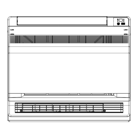
Summary and Features Indoor Unit Remote Controller YAA1FB1F... -
Page 5: Safety Precautions
Removal Procedure 1.Safety Precautions Installing, starting up, and servicing air conditioner can be ●Make sure the outdoor unit is installed on a stable, level hazardous due to system pressure, electrical components, and surface with no accumulation of snow, leaves, or trash equipment location, etc. -
Page 6: Unit.specifications
Model. KM09HEDI KM12HEDI Product.Code CV010N00900 CV010N01000 Rated.Voltage V ~ 208/230 208/230 Power.Supply Rated.Frequency Phases Power.Supply.Mode Outdoor Outdoor Cooling.Capacity. Btu/h 9000 12000 Heating.Capacity. Btu/h 9500 13000 Air.Flow.Volume(SH/H/MH/M/ML/L/SL) 500/430/410/370/330/280/250 600/520/480/440/400/360/280 Dehumidifying.Volume Application.Area 12-18 15-22 Fan.Type Centrifugal Centrifugal Diameter.Length(DXL). Φ80X370 Φ80X370 Fan.Motor.Cooling.Speed.(SH/H/ r/min... - Page 7 Model. KM18HEDI Product.Code CV010N01100 Rated.Voltage V ~ 208/230 Rated.Frequency Power.Supply Phases Power.Supply.Mode Outdoor Cooling.Capacity. Btu/h 18000 Heating.Capacity. Btu/h 19800 Air.Flow.Volume(SH/H/MH/M/ML/L/SL) 650/620/550/500/450/410/320 Dehumidifying.Volume Application.Area 23-34 Fan.Type Centrifugal Diameter.Length(DXL). Φ80X370 Fan.Motor.Cooling.Speed.(SH/H/MH/M/ML/L/SL). r/min 840/800/720/650/580/530/410 Fan.Motor.Heating.Speed(SH/H/MH/M/ML/L/SL) r/min 900/840/760/690/620/570/450 Output.of.Fan.Motor Fan.Motor.RLA Evaporator.Form. Aluminum.Fin-copper.Tube Pipe.Diameter Φ6.35 .Gap 2-1.2 Coil.Length.(LXDXW)..
-
Page 8: Specifications
Specifications 2.2 Noise Criteria Curve Tables for Both Models Quiet Med-low Medium Med-high High Turbo Indoor Fan Motor Rotating Speed... -
Page 9: Construction Views
Constrction Views 3. Construction Views Unit:mm... -
Page 10: Refrigerant System Diagram
Refrigerant System Diagram 4. Refrigerant System Diagram outdoor indoor filter A heat exchanger filter outdoor heat exchanger 4-way valve B heat exchanger filter high pressure switch Note: Not available for 14K/18K model discharge silencer C heat exchanger discharge temperature sensor filter D heat exchanger gas -liquid separator... -
Page 11: Schematic Diagram
Schematic Diagram 5. Schematic Diagram 5.1 Electrical Data Meaning of marks Symbol Color symbol Symbol Color symbol BLUE BROWN YELLOW BLACK YEGN YELLOW GREEN VIOLET WHITE ORANGE PROTECTIVE EARTH 5.2 Electrical Wiring TUBE ROOM TEMP. TEMP. RECEIVER AND MOTOR SENSOR SENSOR DISPLAY BOARD DISPLAY... -
Page 12: Printed.circuit.board
Schematic Diagram 5.3 Printed Circuit Board ●TOP VIEW Communication interface for Terminal used for Connect earthing wire Live wire input Neutral wire input controlling lower swing indoor and outdoor units Terminal of display Needle block of Indoor tube Indoor ambient Terminal of upper swing interface jumper cap... -
Page 13: Function And Control
Function and Control 6. Function and Control 6.1 Remote Control Operations ON/OFF Press it to start or stop operation. Press it to decrease temperature setting. : Press it to increase temperature setting. MODE Press it to select operation mode (AUTO/COOL/DRY/FAN/HEAT). Press it to set fan speed. - Page 14 Function and Control MODE Each time you press this button,a mode is selected in a sequence that goes from AUTO,COOL,DRY, FAN,and HEAT * , as the following: COOL HEAT AUTO * Note:Only for models with heatingf unction. After energization, AUTO mode is defaulted. In AUTO mode, the set temperature will not be displayed on the LED of the indoor, and the unit will automatically select the suitable operation mode in accordance with the room temperature to make indoor room comfortable.
- Page 15 Function and Control Sleep 2 is sleep mode 2, that is air condi tioner will run according to the prese tting a group of sleep tempera ture curve. Sleep 3- the sleep curve setting under Sleep mode by DIY: (1)Under Sleep 3 mode,press"Turbo"button for along time,remote control enters into user individuation sleep setting status, at this time,the time of remote control will display"1 hour",the settingt emperature "88"...
- Page 16 Function and Control LIGHT: Press LIGHT button to turn on the display's light and press this button again to turn off the display's light. If the light is turn- ed on , is displayed. If the light is turned off, disappears.
-
Page 17: Description.of.each.control.operation
Function and Control 6.2 Description of Each Control Operation 1. Cooling mode (1).Under.this.mode,.the.fan.and.the.up.swing.will.operate.at.setting.status..The.temperature.setting.range.is.16~30ºC. (2).The.unit.is.stopped.because.of.malfunction.of.outdoor.unit.or.protection..The.indoor.unit.keeps.original.operation.status.and.the error.code.is.displayed. (3).Indoor.unit.is.stopped.due.to.mode.shock. 2. Drying mode (1).Under.this.mode,.the.fan.operates.at.low.speed.and.the.swing.operates.at.setting.status..The.temperature.setting.range.is 16~30ºC. (2).The.unit.is.stopped.because.of.malfunction.of.outdoor.unit.or.protection..The.indoor.unit.keeps.original.operation.status.and.the error.code.is.displayed. 3. Heating mode (1).Under.this.mode,.the.temperature.setting.range.is.16~30ºC. (2).Working.condition.and.process.for.heating When.the.unit.is.turned.on.under.heating.mode,.the.indoor.unit.turns.to.cold.air.prevention.status..When.the.unit.is.turned.off.and.the indoor.unit.has.been.started.up.before,.the.indoor.unit.blows.the.residual.heat. (3).Protection.function:.When.the.compressor.is.stopped.due.to.malfunction.under.heating.mode,.the.indoor.unit.blows.the residual.heat. (4).Blow.residual.heat When.the.unit.stops.operation.as.it.reaches.the.temperature.point,.indoor.unit.will.continue.to.run.for.60s..The.fan.speed.cant.be switched.during.blowing.residual.heat.period..The.upper.horizontal.louver.will.turn.to.the.defaulted.position.in.cooling..When.the.unit operates.under.heating.mode.or.auto.heating.mode,.compressor.will.be.turned.on.and.the.corresponding.electric.expansion.valve.is more.than.65.and.the.unit.stops.operation.during.the.operation.status.of.indoor.unit..The.upper.horizontal.louver.will.turn.to.the defaulted.position.in.heating.mode..The.indoor.unit.operates.at.low.speed.for.10s.and.then.the.unit.stops.operation. (5).Defrosting,.oil-returning As.it.received.the.signal.of.defrosting.and.oil-returning.from.outdoor.unit,.the.upper.horizontal.louver.will.turn.to.the.minimum.angle.in cooling..10s.later,.the.in.door.fan.stop.operation..During.defrosting.and.oil-returning.process.and.they.are.quitted.within.5mins,.all malfunctions.for.indoor.tube.temperature.sensor.wont.be.detected. - Page 18 Function and Control 7.4 I FEEL function When.I.FEEL.command.is.received,.the.controller.will.operate.according.to.the.ambient.temperature.sent.by.the.remote.controller.(For defrosting.and.cold.blow.prevention,.the.unit.operates.according.to.the.ambient.temperature.sensed.by.the.air.conditioner)..The. remote.controller.will.send.ambient.temperature.data.to.the.controller.every.10min..When.the.data.has.not.been.received.after.11. mins,the.unit.will.operate.according.to.the.temperature.sensed.by.the.air.conditioner..If.I.FEEL.function.is.not.selected,.the.ambient temperature.will.be.that.sensed.by.the.air.conditioner..I.FEEL.function.will.not.to.be.memorized. 7.5 Timer function General.timer.and.clock.timer.functions.are.compatible.by.equipping.remote.controller.with.different.functions. General.Timer Timer.ON.can.be.set.at.unit.OFF..If.selected.ON.time.is.reached,.the.unit.will.start.to.operate.according.to.previous.setting.status.. Time.setting.range.is.0.5-24hr.in.30-minute.increments. Timer.OFF.can.be.set.at.unit.ON..If.selected.OFF.time.is.reached,.the.unit.will.stop.operation..Time.setting.range.is.0.5-24hr.in 30-minute.increments. 7.6 Sleep function This.mode.is.only.valid.in.cooling.and.heating.modes..The.unit.will.select.proper.sleep.curve.to.operate.according.to.different.set temperature. 7.7 Switchover function for defrosting mode If.H1.isnt.displayed.on.remote.controller.under.OFF.status,.the.unit.will.turn.to.“defrosting.mode.1”.after.the.unit.is.turn.on.by.remote controller..After.indoor.unit.receives.remote.control.signal,.it.will.send.“defrosting.mode.1”.to.outdoor.unit..If.H2.is.displayed.on. remote.controller.under.OFF.status,.the.unit.will.turn.to.“defrosting.mode.2”.after.the.unit.is.turn.on.by.remote.controller..After.indoor. unit.receives.remote.control.signal,.it.will.send.“defrosting.mode.2”.to.outdoor.unit. Under.OFF.status,.press.MODE.and.AUXILIARY.button.simultaneously.on.remote.controller.to.switch.“defrosting.mode.1”.and “defrosting.mode.2”. 7.8 Compulsory defrosting function When.the.unit.is.turned.on.in.heating.by.remote.controller.and.the.set.temperature.is.16 C,.press.“+,-,+,-,+,-”continuously.within.5s,.
-
Page 19: Installation Manual
Installation Manual 7. Installation Manual 7.1 Seleection of Installation Location ● Such a place where cool air can be distributed throughout the room. Location for securing the installation panel. ● Such a place where condensation water is easily drained out. ●... -
Page 20: Refrigerant.piping
Installation Manual 7.4 Refrigerant piping 1)Drill a hole ( 55mm in diameter ) in the spot indicated by the symbol in the illustration as below . 2)The location of the hole is different depending on which side of the pipe is taken out . 3)For piping ,see Connecting the refrigerant pipe ,under Indoor Unit Installation(1). - Page 21 Installation Manual 7.7 nstalling indoor unit 3 tabs 1.Preparation Casing ●Open the front panel, remove the 4 screws and dismount Front the front grille while pulling it forward. grille ●Follow the arrows to disengage the clasps on the front case to remove it. Front panel Remove ●Follow the procedure below when removing the slit portions.
-
Page 22: Connecting.the.refrigerant.pipe
Installation Manual 3) Once refrigerant piping and drain piping connections are complete, fill in the gap of the through hole with putty. A gap can lead to condensation on the refrigerant pipe, and drain pipe, and the entry of insects into the pipes. 4) Attach the front panel and front grille in their original positions once all connections are complete. -
Page 23: Checking.for.gas.leakage
Installation Manual 1. Selection of copper and heat insulation materials Inter-unit wiring When using commercial copper pipes and fittings, observe the Gas pipe following: Liquid pipe 1)Insulation material: Polyethylene foam Heat transfer rate:0.041 to 0.052W/mK(0.035 to 0.045kca/(mh Liquid pipe Refrigerant gas pipes surface temperature reaches 110 max. Gas pipe insulation insulstion... - Page 24 Installation Manual 4)Pull wires to make sure that they are securely latches up, then retain wires with wire retainer. 5)In case of connecting to an adapter system, Run the remote controller cable and attach the S21. (Refer to 11. When connecting go an system.) Sensor securing plate Firmly fix the wires with the...
-
Page 25: Exploded Views And Parts List
Exploded Views and Parts List 8. Exploded Views and Parts List Models:KM09HEDI KM12HEDI... - Page 26 Exploded Views and Parts List Part Code Description KM09HEDI KM12HEDI Product Code CV010N00900 CV010N01000 Front Panel Assy 20012756 20012756 Filter Sub-Assy 11122119 11122119 Front Case Assy 20012601 20012601 Evaporator Assy 01002634 01002626 Temp Sensor Sleeving 05212423 05212423 Rear Case assy...
- Page 27 Exploded Views and Parts List Model:KM18HEDI...
- Page 28 Exploded Views and Parts List Part Code Description KM18HEDI Product Code CV010N01100 Front Panel Assy 20012756 Filter Sub-Assy 11122119 Front Case Assy 20012601 Evaporator Assy 01002608 Temp Sensor Sleeving 05212423 Rear Case assy 22202462 Centrifugal Fan 10312005 Fan Motor 15012123 Step Motor 1521210805 Crank...
-
Page 29: Troubleshooting
Troubleshooting 9. Troubleshooting 9.1 Precautions before Performing Inspection or Repair Be.cautious.during.installation.and.maintenance..Do.operation.following.the.regulations.to.avoid.electric.shock.and.casualty.or.even death.due.to.drop.from.high.altitude. *.Static.maintenance.is.the.maintenance.during.de-energization.of.the.air.conditioner..For.static.maintenance,.make.sure.that.the.unit is.de-energized.and.the.plug.is.disconnected. *.Dynamic.maintenance.is.the.maintenance.during.energization.of.the.unit..Before.dynamic.maintenance,.check.the.electricity.and. ensure.that.there.is.ground.wire.on.the.site..Check.if.there.is.electricity.on.the.housing.and.connection.copper.pipe.of.the.air.condi- tioner.with.voltage.tester..After.ensure.insulation.place.and.the.safety,.the.maintenance.can.be.performed.Take.sufficient.care.to.avoid. directly.touching.any.of.the.circuit.parts.without.first.turning.off.the.power. At.times.such.as.when.the.circuit.board.is.to.be.replaced,.place.the.circuit.board.assembly.in.a.vertical.position. Normally,diagnose.troubles.according.to.the.trouble.diagnosis.procedure.as.described.below.(Refer.to.the.check.points.in.servicing written.on.the.wiring.diagrams.attached.to.the.indoor/outdoor.units.) NO. Troubleshooting.procedure Confirmation Judgement.by.Flashing.LED.of.Indoor/Outdoor.Unit How.to.Check.simply.the.main.part 9.2 Confirmation (1)Confirmation.of.Power.Supply Confirm.that.the.power.breaker.operates(ON).normally; (2)Confirmation.of.Power.Voltage Confirm.that.power.voltage.is.AC.220-230-240.±10%..If.power.voltage.is.not.in.this.range,.the.unit.may.not.operate.normally. 9.3 Flashing LED of Indoor/Outdoor Unit and Primary Judgement Malfunction, st atus display table Malfunction name Malfunction... -
Page 30: How.to.check.simply.the.main.part
Troubleshooting 9.4 How to Check Simply The Main Part (1) Troubleshooting for malfunction of temperature sensor main.check.point: ●Whether.the.temperature.sensor.is.broken.or.damaged; ●Whether.the.temperature.sensor.terminal.is.loosened.or.not.connected; ●Whether.the.mainboard.is.damged; Check.flow.chart: Start the troubleshooting for temperature sensor Check whether the temperature sensor and wiring terminal is loosened or poorly connected? Insert the temperature sensor well Is mafunction... - Page 31 Troubleshooting (2) Troubleshooting for communiction malfunction Main.check.point: ●Check.whether.the.connection.wire.for.indoor.and.outdoor.units.and.the.wires.inside.the.indoor.unit.is.connected.well; ●Check.whether.the.mainboards.of.indoor.unit.or.outdoor.unit.are.damaged; Check.flow.chart: Communication malfunction for some indoor unit Disconnect the power, and check connection wire for indoor and outdoorunits and wires inside electric box areconnected correctly Connect wires according to wiring Is malfunction Wires are connected eliminate? diagram...
- Page 32 Troubleshooting All indoor units alarms communication malfunction Disconnect the power, and check connection wire for indoor and outdoor units and wires inside electric box are connected correctly Connect wire Wires are connectly according connected correctly? Is malfunction eliminated? to wiring diagram Disconnect the power, and check whether theconnection wires between mainboard of outdoorunit and filter palte are connected...
- Page 33 Troubleshooting (3) Troubleshooting for C5 malfunction Display displays C5 Check whether the Insert the jumper mainbaord ofcontroller is inserted with thejumper cap? Is malfunction eliminated? Check Re-insert the jumper whether the jumper cap is poorly connected? Is malfunction eliminated? Replace the jumper Is malfunction eliminated? It's the malfunction...
- Page 34 Troubleshooting (4)Troubleshooting for H6 malfunction Start the troubleshooting for H6 malfunction Check whether the terminal of DC motor is connected tightly Insert the motor terminal tightly Is mafunction eliminated? Pull blade with hand to see whether it can rotate smoothly Re-assemble blade and motor correctly Is mafunction...
- Page 35 Troubleshooting Appendix Appendix 1: Resistance Table of Ambient Temperature Sensor for Indoor and Outdoor Units(15K) Temp.(℃) Resistance(kΩ) Temp.(℃) Resistance(kΩ) Temp.(℃) Resistance(kΩ) Temp.(℃) Resistance(kΩ) 138.1 18.75 3.848 1.071 128.6 17.93 3.711 1.039 121.6 17.14 3.579 1.009 16.39 3.454 0.98 108.7 15.68 3.333 0.952 102.9...
- Page 36 Troubleshooting Appendix 2: Resistance Table of Outdoor and Indoor Tube Temperature Sensors(20K) Temp.(℃) Resistance(kΩ) Temp.(℃) Resistance(kΩ) Temp.(℃) Resistance(kΩ) Temp.(℃) Resistance(kΩ) 181.4 25.01 5.13 1.427 171.4 23.9 4.948 1.386 162.1 22.85 4.773 1.346 153.3 21.85 4.605 1.307 20.9 4.443 1.269 137.2 4.289 1.233 129.9...
- Page 37 Troubleshooting Appendix 3: Resistance Table of Outdoor Discharge Temperature Sensor(50K) Temp.(℃) Resistance(kΩ) Temp. ( ℃) Resistance(kΩ) Temp.(℃) Resistance(kΩ) Temp. ( ℃) Resistance(kΩ) 853.5 18.34 4.754 799.8 93.42 17.65 4.609 89.07 16.99 4.469 703.8 84.95 16.36 4.334 660.8 81.05 15.75 4.204 620.8 77.35 15.17...
-
Page 38: Removal Procedure
Removal Procedure 10. Removal Procedure Be sure to wait for a minimum of 10 minutes after Warning turning off all power supplies before disassembly. Steps Procedure 1.Remove panel Pull the slide clasps at both sides of panel, pull the panel outwards, lift up the panel and then remove the panel. - Page 39 Removal Procedure Steps Procedure 4.Remove swing assy swing assy Remove 2 screws fixing swing assy, pull out the connection wires with electric box, screw and then pull the swing assy outwards to remove it. 5.Remove water tray assy Remove 2 screws fixing water tray, and then pull the water tray outwards to remove it.
- Page 40 Removal Procedure Steps Procedure 7.Remove piping stopper Loosen clasps between piping stopper and bottom case, and then pull the piping stopper outwards to remove it. piping stopper 8.Remove evaporator Loosen the clasps between evaporator and bottom case and then pull the evaporator outwards to remove it.
- Page 41 Removal Procedure Steps Procedure 10.Remove centrifugal blade Remove nuts on centrifugal blade, and then pull the centrifugal blade outwards to remove it. centrifugal blade 11.Remove motor support Remove screws fixing motor support, and then remove the motor support. motor support 12.Remove motor wire clamp Loosen clasps between motor wire clamp and bottom case, and then pull the motor...
- Page 42 Removal Procedure Steps Procedure 13. Remove motor Remove the motor. motor...
- Page 43 GREE ELECTRIC APPLIANCES,INC.OF ZHUHAI Add:Jinji.west.Rd.Qianshan.Zhuhai.Guangdong.China...
Need help?
Do you have a question about the KM09HEDI and is the answer not in the manual?
Questions and answers