Table of Contents
Advertisement
Introduction
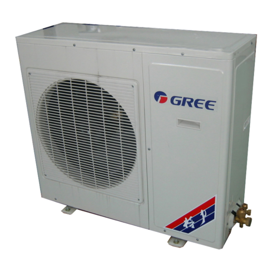
In this technical service manual, you will find rich references to KF(R)-70DW/NA1
model including photoes, technical specifications, explosive views, spare parts lists and
circuit diagrams. Service people and engineers of Gree' s customers and distributors would
find it a very handy source of technical information of our products.
Contents
1 .......................................................1
Summary
2 ...................................................3
Technical and specifications
4 ..................................................8
5 ......................................................10
6 .....................................................11
7 .......................................12
9 .............................................35
10 .....................................................40
11 ... .....................................................41
KF(R)-70DW/NA1 Technical Service Manual
Technical Support Group
Mar.2004
Advertisement
Table of Contents

Related Manuals for Gree KF-70DW/NA1


Summary of Contents for Gree KF-70DW/NA1
-
Page 1: Table Of Contents
In this technical service manual, you will find rich references to KF(R)-70DW/NA1 model including photoes, technical specifications, explosive views, spare parts lists and circuit diagrams. Service people and engineers of Gree' s customers and distributors would find it a very handy source of technical information of our products. - Page 2 Summary 1. Note Model KF-70DW/NA1 1Ph 230V 50Hz R407C KFR-70DW/NA1...
- Page 3 2. Technical specifications Model KF-70DW/NA1 Function COOLING Power Supply (Phase-Frequency-Voltage) 1Ph – 230V – 50Hz Capacity 7000 Rated Input 3100 Rated Current 15.2 Recycling Air Volume 1170 Dehumidifying Volume (L/h) C.O.P / EER (W/W) 2.26 Model KF-70D/NA1 Motor Fan Speed (r/min) (H/M/L)
- Page 4 Defrosting Method Auto defrost Noise dB (A) Outdoor unit Dimension (W/D/H)( mm) 950x412x840 Dimension of Package (W/D/H)( mm) 1100x450x920 Net Weight /Gross Weight (kg) 75/87 Refrigerant Charge (kg) R407C/2.4 Length Φ9.52(3/8”) Connecting Pipe Outer Liquid Pipe (mm) Φ16(5/8”) Diameter Gas Pipe (mm) Height Distance...
- Page 5 Model KFR-70DW/NA1 Function COOLING HEATING Power Supply (Phase-Frequency-Voltage) 1Ph – 230V – 50Hz Capacity 7000 8500 Rated Input 3000 3050 Rated Current 14.6 15.1 Recycling Air Volume 1170 Dehumidifying Volume (L/h) C.O.P / EER (W/W) 2.79 Model KFR-70D/NA1 Motor Fan Speed (r/min) (H/M/L) 1360/1280/1240 Output Power (w) Fan Type-Piece...
- Page 6 Defrosting Method Auto defrost Noise dB (A) Outdoor unit Dimension (W/D/H)( mm) 950x412x840 Dimension of Package (W/D/H)( mm) 1100x450x920 Net Weight /Gross Weight (kg) 75/87 Refrigerant Charge (kg) R407C/2.5 Length Φ9.52(3/8”) Connecting Pipe Outer Liquid Pipe (mm) Diameter Φ16(5/8”) Gas Pipe (mm) Height Distance...
-
Page 7: 3 ........................................................7 Names And Spare Parts
Names of spare parts Indoor unit Left decoration plate LED board Air guide louver Right decoration plate Front grill Wireless remote control Wrapping tape Outdoor unit Air in Connection pipe Valve Air out... -
Page 8: Outlines And Installation Dimensions
4. Outlines and installation dimension 4.1 Outlines and dimensions of indoor unit 1300 188 150cm or more 60cm or more 60cm or more 30cm 100cm or more or more... -
Page 9: Outlines And Dimensions Of Outdoor Unit
4.2 Outlines and dimensions of outdoor unit 65 106 :mm Unit Front grill Gas pipe Liquid pipe Handle Wire hole More than 500mm 500mm More than More than More than 1000mm 1000mm More than 300mm Obstructions 2000mm More than Air outlet More than 1000mm Floor... -
Page 10: Working Principle Diagram
Working principle diagram 5.1 Cooling system diagram for cooling only type Filter Evaporator Cross flow fan Capillary Axial flow fan Condenser Gas-liquid separator Compressor When the power is on, indoor and outdoor units will start to run. The compressor sucks low-pressure refrigerant gas from the evaporator of indoor unit and then discharges high-temperature, high-pressure refrigerant gas into outdoor condenser. -
Page 11: Circuit Diagram
6. Circuit diagram The circuit diagram are subject to change , please refer to the ones on the machine. KF-70DW/NA1 KFR-70DW/NA1... -
Page 12: Pcb Function Manual
PCB function manual 8 7. Temperature parameter ① The room ambient temperature: (Tamb) ② The room evaporator temperature:(Tevaporator) ③ The outdoor condenser temperature: (Tcondenser) ④ The exhasut temperature:(Texhaust) Foundamental functions In each mode, the compressor starts at once, it will not stop within 6min according to the changes of Tamb, when it stopped once, after 3mins delayed, can start it again. -
Page 13: Heat Mode
Ambient temp. Tamb Start cooling Tset Setting temp. Tset Dry operation Tset Stop cooling 6min 6min 4min 4min Compressor Outdoor fan Indoor fan Low speed Low speed Low speed Low speed Low speed Stop running Running 7.2.3 HEAT Mode When Tamb≤Tset-1℃ enter into HEAT mode, reversing valve, compressor, outdoor fan motor start to work. indoor fan motor runs at setting fan speed and anti-cool wind. -
Page 14: Fan Mode
Condenser pipe temp Tcon Outdoor fan Reversal vavle Run at anti-cool wind Indoor fan 44min 45min 55min Running Stop running FAN mode 7.2.4 Indoor fan motor runs at setting fan speed: HIGH AUTO Temp. setting range is 16 ℃~ 30 ℃ . 7.2.5 Auto mode When Tamb>2 ℃, it runs at cool mode, indoor setting temp. - Page 15 Indoor it will come back to display, controller runs at setting mode. evaporator temp.Teva 3min 10min 4min Compressor Outdoor fan Indoor fan Swing motor Stop running Running In DRY mode, it will run for 6min, and stop running for 4min, after compressor has run for 3min, and had continuously 3min detected Ttube<- 2℃, compressor, outdoor and indoor fan will run in low fan speed, and E2 is displayed.
-
Page 16: Low Voltage Protection
If the above phenomenons existed, the unit cannot resume to run, E4 will be display. Press ON/OFF button to turn off the unit, repress ON/OFF button return to run at the original running mode. 7.3.5 Indoor ultra high temperature protection In HEAT mode, when detected the evaporator tube temp. -
Page 17: Swing Control
7.5.1 SWING Control Use SWING button to start or stop the control, only when indoor fan motor is running the SWING operation is available. 7.5.2 The buzzer control When controller is powered on or received the signals, the buzzer will sound. 7.5.3 The auto fan speed control of the fan motor In HEAT mode:... -
Page 18: Names And Functions Of Wireless Remote Control
飞 碟 系 列 Names and functions of wireless remote control Note: Be sure that there are no obstructions between receiver and wireless remote control. The wireless remote control could receive the signal within 10 meters. Don't drop or throw the wireless remote control. ... - Page 19 Names and functions of wireless remote control(Remove the cover) Note: This type of wireless remote control is a kind of new current control. Some buttons of the control which are not available to this air conditioner will not be described below. Liquid crystal displayer It shows all set contents.
-
Page 20: Cool Mode Operation
7.10 COOL mode operation Microcomputer will accord to the room sensor detected the temp. and setting temp. differences to start the cool operation or not. The room sensor detected temp. is higher than setting temp., the cool mode operate. The room sensor detected temp. is lower than setting temp., indoor fan motor will stop running, water valve will be turned off, cool operation will stop. -
Page 21: Heat Mode Operation
7.11 HEAT mode operation When room sensor detected temp. is lower than setting temp., heat mode start running. When room sensor detected temp. is higher than setting temp., indoor fan motor stop running, water valve is turned off, heat operation is stopped. The setting range is Press SWING button, the louver guide will automatically... -
Page 22: Dry Mode Operation
7.12 DRY mode operation When room sensor detected the temp. is lower than setting temp. 2℃ or more, the water valve, indoor fan motor stop running. When room sensor detected the temp. is between the ± 2℃ of the setting temp. it will enter into dry mode operation, when room sensor detected the temp. -
Page 23: Auto Mode Operation
7. 13 AUTO mode operation In AUTO mode, the standard cooling setting temp. is 25 , the standard heating setting temp. is 20 When plug in, press 1/0 unit will start to run. Press MODE button to select AUTO mode. Microcomputer will accord to indoor temp. - Page 24 TIMER operation mode 7.14 At stopping, can set timer on, each time to press TIMER ON the time will be increased 0.5h, circulates as below: Cancel At running, can set timer off, each time to press TIMER OFF, the time will be increased 0.5h, circulates as below: Cancel...
-
Page 25: Sleep Mode Operation
7.15 SLEEP mode operation In cool and dry modes, set the sleep operation and run for 1 hour later, the setting temp. will be increased 1℃, 2hours later, the setting temp. will be increased 2℃ , then it runs at the setting temp. - Page 26 7.16 Guide for operation Remove the cover from the back, take out the old batteries. Insert two batteries. (pay attention to the Polarity) 3. Re-attach the cover. NOTE: Never mix new and used or diff- erent types of two batteries to insert.
-
Page 27: 8 .......................................................27 Disassemble Procedures
Disassembly procedures 8-1. Disassembly procedures for indoor unit Dissassembly Procedures/Photoes 1. Remove the front grill assy Front grill assy To remove the clasps of the front grill assy Clasp by tools downward, until the front grill is opened. 8-1 Fig. 2.... - Page 28 Dissassembly Procedures/ Photoes Disassemble the guide louver assy Take out the guide louver from the guide louver holder, then take out the both ends from Fig. 8-8 the swing motor. Assorted position of guide louver and guide louver holder Disassemble the water-tray assy To screw off 3pcs bolts in the photoes can disassemble the water-tray assy.
- Page 29 Dissassembly Procedures/ Photoes 9. Disassemble the aire outlet rear side plate assy a. Firstly to remove the velveteen and the left and right sides ' of liners .; b. To screw off the bolts as shown in the Fig. with screw driver. 8-17...
- Page 30 Dissassembly Procedures/ Photoes 13. Disassemble the bearing mounting plate Fig. 8-26 To screw off 4pcs bolt in the fig. with screwdriver. Bolt Disassemble the motor Fig. 8-27 To loose the bolts in the fig with screwdriver, can take out the motor clamp and motor fixing Bolt hoop.
- Page 31 The disassembly procedures for outdoor unit 8-2. Dissassembly Procedures/ Photoes 1. Disassemble the top cover Top cover To screw off the bolts around the top cover then lift it upward can take off the top cover. As shown in Fig. 8-35...
- Page 32 Dissassembly Procedures/ Photoes 4. Disassemble the electrical appliances mounting plate Bolts Disassemble 3pcs bolt which are fixing the electric mounting plate, pull out the lead wire insert of the compressor and fan motor, take out the electrical appliances mounting plate. 8-38...
- Page 33 Dissassembly Procedures/ Photoes 7. Disassemble the fan blade of outdoor unit To screw off the laeotropic nut, can take off the fan blade. Laeotropic nut 8-41 Fig. 8. Disassemble the outdoor unit motor To screw off the fixing bolt of motor and motor support, and pull out the connection wire of the motor, can take off the motor.
- Page 34 Dissassembly Procedures/ Photoes 10. Disassemble the capillary Unsolder the solder point of the capillary, valve gate and condenser gate, then can dis- assemble the capillary, make Capillary assy sure that do not let any weld- ing dregs to block the capillary. As show in right fig.
-
Page 35: Explosive View And Spare Parts List
Explosive view and spare parts lists 9.1 For KF(R)-70DW/NA1 Explosive view of indoor unit spare parts... - Page 36 9.2 Spare parts lists of indoor unit Part Code Description KFR-70D/NA1 KF-70D/NA1 Left Decoration Plate 26112417 26112417 导板挤塑条左装饰板 10512025 10512025 Shaft of Louver I 导风板转轴I 01332410 01332410 Swing Louver Fixer 扫风叶片安装板 24212020 24212020 Louver Support 导风板支架 Louver Fixer 24222016 24222016 导风板固定架...
- Page 37 11122012 Filter 引水板组件 01362401 01362401 Water Lead Plate 面板格栅 22412011 22412011 Front Grill 面板格栅卡扣2 26252003 26252003 Front Grill Clip 2 遥控器Y512(GREE) 30512506 30512506 Remote Controller Y512 蒸发器部件 01002405 01002405 Evaporator Assy 面板格栅卡扣1 26252002 26252002 Front Grill Clip 1 感温包 390001215...
- Page 38 9.3 For KF(R)-70DW/NA1 Explosive view of outdoor unit spare parts...
- Page 39 9.4 Spare parts lists of outdoor unit Part Code Part Code Description KF-70W/dNA1 KF-70W/dNA1 400321531 40032140 信号控制线 Signal Cable 40020454 40020454 电源连接线 # Connecting Cable 400203181 400203181 电源线 # Power Cord 22265251 22265251 面罩 Front grill 01435254 01435254 外罩 Front plate 10335253 10335253 轴流风叶...
-
Page 40: 10.Care And Maintenance
10.Care and maintenance Warning: Please turn power off before maintenance. Cleaning the filter 10.1 Take out the filter, use the dust collector to clean, if it is too dirty could use the soap water to clean. Make sure to dry the filter then can reinsert it. Advice: If the filter is too dirty that will affect the air in volume, so that make the system overloaded and consum more than 6% of electric energy. -
Page 41: Trouble Shooting
11. Trouble shooting Trouble shooting When circuit breaker is Earth, tested insulated set to "ON", will trip off to confirm whether it is at once. electricity leakage or not. The circuit breaker trip off( Or fuse is melt) When turn the unit to Check the breaker, "ON", thebreaker trip off test the resistance... - Page 42 Clean the filter Air filter is blocked Air circulation volume is not enough. Set the fan speed to high Fan speed is too low or middle speed The outdoor unit installation place should be The installation place of indoor unit is not suitable well ventilated, and should be installed awning.
- Page 43 Compressor malfunction Replace the compressor In COOL, DRY mode, outdoor fan motor Compressor running capacity Replace the capacity broken runs, but compre- ssor does not op- Voltage is too low or too high Suggest to equip the manostat erate. According to the circuit diagram Wrong wiring to wire correctly.
Need help?
Do you have a question about the KF-70DW/NA1 and is the answer not in the manual?
Questions and answers