Table of Contents
Advertisement
Advertisement
Table of Contents

Subscribe to Our Youtube Channel
Related Manuals for Gree KFR-25GW/NaA512


Summary of Contents for Gree KFR-25GW/NaA512
-
Page 1: Summary And Features
Ultra thin split unit series Summary and features Models Remarks... - Page 2 Models Remarks...
- Page 3 Ultra thin split unit series Models Remarks...
- Page 4 Technical and specifications Parameters of single-split type unit Model Cooling Heating Cooling Cooling Heating Heating Function Rated voltage Frequency Capacity Nominal power Rated power Rated current Air volume Dehumidify volume Model Fan motor speed Output power (W) Auxiliary electric heater power Fan motor capacity Fan motor running current Fan type-piece...
- Page 5 Ultra thin split unit series Model GK080PAD Compressor model Compressor type Rotary Block current Compressor running current Compressor input power Compressor overload model M PA12009-12026 Throttling method Capillary Capacity Starting method Working temperature range Aluminum fin-copper tube Condenser Pipe diameter Row-fin distance (mm) Heat exchanger unfold area Fan motor speed (rpm)
- Page 6 Parameters of dual-split type unit Model Cooling Heating Heating Heating Cooling Cooling Function Rated voltage Rated frequency Capacity Nominal power Rated power Rated current Air volume Dehumidify volume Model Fan motor speed Motor output power (W) Auxiliary electric heater power Fan motor capacity Fan motor running current Fan type-piece...
- Page 7 Ultra thin split unit series Model Compressor model Compressor type Rotary Block current Compressor running current Compressor input power Compressor overload model Throttling method Capillary Starting method Capacitance Working temp. range Condenser Aluminum fin-copper tube Pipe diameter Row-fin distance (mm) Expanding area of heat exchanger (IXHXL) Fan motor speed (rpm) Motor rated power (W)
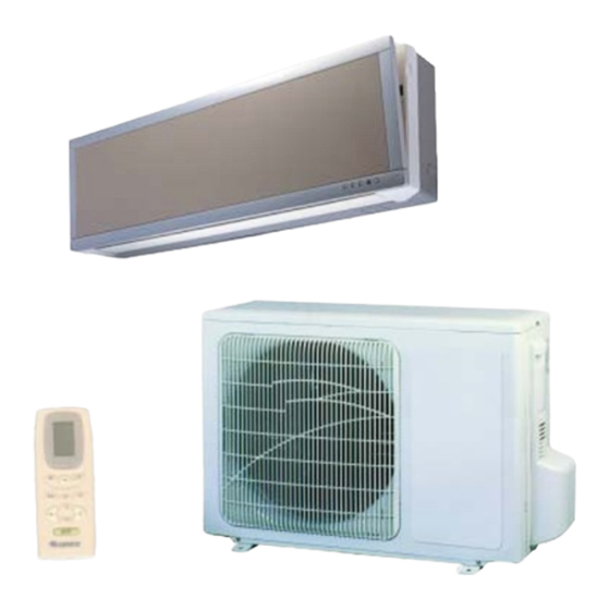
- Page 8 Spare part name Name of spare parts of single-split type unit Air in Front panel Filter Indoor unit Covering plate Power Air out plug Wireless remote control : HEAT (The light of cooling only unit will not on) : COOL/DRY :...
- Page 9 Ultra thin split unit series Name of spare parts of dual-split type unit Air in Front panel Filter Covering plate Indoor unit Air in Air out Front panel Filter Covering plate Air out Connection pipe and connection wire Connection pipe and connection wire Wireless remote control HEAT (The light of cooling only unit will not on)
-
Page 10: Outline And Installation Dimension
Outline and installation dimension Air inlet vent Right outlet pipe Left outlet pipe Rear view Ceiling Left Right Wall mounted plate... - Page 11 Ultra thin split unit series Handle Screw Spanner...
- Page 12 Unit:mm Model KFR-25×2W/NaA512 KFR-60W2/NaA512 KFR-35×2W/NaA512 Screw Spanner...
-
Page 13: System Principle Diagram
Ultra thin split unit series System principle diagram One-way valve Filter Evaporator Main capillary Cross flow fan Auxilary capilary Axial flow fan Condenser Magnetic 4-way valve Heating Cooling Liquid and gas Compressor separator When the power is on, indoor unit , outdoor unit start to work. When the system is runnng in cool mode, the compressor sucks low-temperature, low-pressure, refrierant gas from indoor evaporator and then discharges high-temperature, high-pressure refrigerant gas into outdoor heat exchanger. -
Page 14: Circuit Diagram
6 6 6 6 6 Circuit diagram... - Page 15 Ultra thin split unit series These circuit diagrams are subject to change without notice. Please refer to the ones stuck on the machines.
-
Page 16: Pcb Function Manual And Operation Method
7 7 7 7 7 PCB function manual and operation method PCB function manual This manual is fit for the single-split type, dual-split type of ultra thin unit series Temperature parameter The room set temperature: (Tset) The room ambient temperature:(Tamb) Foundamental functions After electrified, no matter in any circumstances, the twice interval of starting should no less than 3mins, when the first electrified, there are no 3mins delay;... - Page 17 Ultra thin split unit series If Tamb<Tset-2℃,compressor, outdoor fan motor will stop running, indoor fan motor will keep low fan speed running. In this mode, the reversal valve will not power on, the setting temp. range :16℃-30℃. Tamb. Cooling Tset Drying Tset 6min. Stop running 4min Compressor Outdoor fan Low fan speed Indoor fan Stop Running Protection Functions Antifreezing Protection When running in Antifreezing protection, the compressor, outter fan motor, stop running, indoor fan motor runs at low fan speed; when antifreezing is eliminated and compressor has stopped for 4min, the unit will run at the original status.
-
Page 18: Protection Function
indicator light flash, when detecting the frost on the condenser had been defrosted, the indoor, outdoor fan motor, 4-way valve start to run at the same time, the compressor keep the original running state, the indicator stop flashing. When electrified the first defrosting time is 9min,then according to the frost situation, to adjust the defrosting time, if frost is too much that the defrosting time will be long(the max. time is 9min.), if frost is less, the defrosting time will be short (at least 3min.), when defrosting finished it will quit. Defrosting Compressor 3min. 9min. Outdoor fan Indoor fan Four-way valve Running Stop Old defrosting mode (multi-split type series) When detected there are frost on the condenser, the system will enter into defrosting status, at this time, the compressor continue to run, outdoor fan motor, 4-way valve, indoor fan motor stop running. -
Page 19: Timer Function
Ultra thin split unit series When it is heating, after set the sleep mode for 1hour, Tset will be declined 1℃; 2hours later, Tset will be declined 2℃,indoor fan will run at low fan speed. 1hour 2hours 2hours above Tset Tset Setting temp. Tset Tset SWING motor control When it is powered on, the guide louver turn to position O with anticlockwise direction, turn off the air outlet vent; when the unit is turned on, if there is no setting swing function, the guide louver will turn to the level position L with clockwise direction air outlet, if turning on the unit to set the swing function, the guide louver will swing from U to D. -
Page 20: Fan Button
Names and functions of wireless remote control of each part Note: Be sure that there are no obstructions between receiver and wireless remote control. Don't drop or throw the wireless remote control. Don't let any liquid in the wireless remote control and put it directly under the sunlight or any place where is very hot. - Page 21 Ultra thin split unit series Note: This type of wirless remote control is a kind of current control, it is applicable to various type (function) of units. Some buttons of the controller which are not available to this air conditioner will not be described below.
-
Page 22: Cool Mode Operation
COOL mode operation According to indoor temp. and setting temp., difference which detected by the room sensor, confirm to start the cooling or not. If the temp. which detected by the room sensor is higher than setting temp., compressor will start to run, unit will run in COOL mode. -
Page 23: Heat Mode Operation
Ultra thin split unit series HEAT mode operation The microcomputer according to difference of temp. and setting temp. which detected by the room sensor, to decide to start the heating or not. When the heating is stopped, fan motor will stop to run. Setting range is Press this button, Press MODE button... -
Page 24: Dry Mode Operation
DRY mode operation If ambient temp. is lower than setting temp. , compressor, indoor and outdoor fan will stop to run. If ambient temp. is between of the setting temp., the unit will run in COOL mode. If room temp. is higher than setting temp. -
Page 25: Auto Mode Operation
Ultra thin split unit series AUTO mode operation In AUTO mode, the setting temp. of COOL is , fan speed could be adjusted. If ambient temp. is in range of , the unit is running in FAN mode. If ambient temp. is higher than , the unit is running in COOL mode. - Page 26 TIMER operation mode T-ON button At stopping, press this button to set Timer on, in range of 0-24h. It will operate as follow: CANCEL T-OFF button At operating, press this button to set Timer off, in range of 0-24h. It will operate as follow: CANCEL...
-
Page 27: Sleep Mode Operation
Ultra thin split unit series SLEEP mode operation Press the button to start the FAN, and set the fan Press MODE button speed. To set Press SLEEP button Press this button to set SLEEP operation. Press SWING button, guide louver will swing automatically, when repressed, guide louver Press the buttons to set stops to swing. -
Page 28: Changing Batteries
Changing batteries Remove the back cover of the wireless remote control. Take out the worn batteries, insert new batteries. (pay at- tention to the polarity) Recover the back cover of Open the wireless remote control. cover NOTE: Don't mix new and used or different types of batteries to insert. -
Page 29: Dissassembly Procedures
Ultra thin split unit series Dissassembly Procedures 8 8 8 8 8 Disassembly procedures for indoor unit Operation procedures/pictures Remove the front panel Front panel Push the front panel upward and pull it from outside, to open the front panel in a certain angle, pull out the bolts of the panel both side, can take off the front panel. - Page 30 Operation procedures/pictures Remove the front case To screw off 3 pieces of screw which fix the front panel, then to pull the clasp of the rear, then take off the front case. As shown in Fig. 8-4: Screw Fig. Remove the electric box cover Electric box cover To loose each clasp which fix the electric box cover, then can take off the electric box cover.
- Page 31 Ultra thin split unit series Operation procedures/pictures Disassemble the electric box Pull out the tube sensor, screw off earth screw, Tube temp. sensor pull out the indoor motor connection wire, to screw off the screw fix the electric box, can Earth screw take out the electric box.
- Page 32 Operation procedures/pictures Disassemble motor Loosen the screws which fix the motor clamp, take out the motor clamp. To screw off the 1pc tighten screw on the cross flow fan right sleeve, can take out the motor. Please refer to Fig. 8-12, 8-13: Motor clamp Screw Fig.
- Page 33 Ultra thin split unit series Disassembly procedure for outdoor unit of single split type unit Operation procedures/pictures Disassemble the top cover and handle To screw off the fixing screw from the handle with Top cover screwdirver, can take off the handle. To screw off 3pcs screw around the top cover, can take off the top cover.
- Page 34 Operation procedures/pictures Remove the electric box To screw off 3pcs screw fixed the electric box, can take off the electric box. As shown in Fig. 8-18: Screw Fig. Remove the right side plate To screw off 5pcs screw from the right side plate with screwdirver, can take off the right side plate.
- Page 35 Ultra thin split unit series Operation procedures/pictures Remove the motor and motor supporter By the use of screw driver to screw off the screw which fix the motor and motor supporter, can remove the motor and motor supporter. As shown in Fig.8-21: Motor Motor supporter Screws...
- Page 36 Operation procedures/pictures Disassemble the capillary Unsold the both side of the capillary sub-assy, can take off the capillary, pay attention do not let the dregs to block the capillary. As shown in Fig. 8-23: Capillary sub-assy Fig. Remove the valve To screw off the screw which fixed the valve with screwdriver, then unsolder the connection pipe which connect with the valve.
- Page 37 Ultra thin split unit series Disassembly procedures for outdoor unit of 70 unit Operation procedures/pictures Remove the front side plate Screw off the screw fixed the front side plate, slide it down, can disassemble the front side plate. As shown in Fig.8-26: Front side plate Screw Fig.
- Page 38 Operation procedures/pictures Remove the cabinet Screw off 8pcs tapping screw which fix the front panel, can disassemble the front panel. As shown in Fig. 8-29: Screw Fig. Remove electric box Pull out the insert of fan motor, and pull out the connection wire of two compressors, to screw off 2pcs tapping screw of electric box, disassemble the electric box.
- Page 39 Ultra thin split unit series Operation procedures/pictures Remove the axial flow fan To screw off the tighten nut which fix the axial flow fan, take off the gasket, spring washer, to pull out the axial flow fan forcibly. As shown in Fig.8-32: Axial flow fan Tighten nut Fig.
- Page 40 Operation procedures/pictures Disassemble four-way valve To remove the tighten nut from the 4-way valve loop, take out the loop, and wrap the 4-way valve with wet gauze, then unsolder the soldered point which connect on the 4-way valve (4pcs for each 4-way valve), take off 4-way valve.
- Page 41 Ultra thin split unit series Operation procedures/pictures Disassemble the compressor Loosen 6pcs nut with washer at bottom of two compressor: (Note: The refrigerant should be discharged at first.) Unsolder the air in, air out pipes of the comressor, be carefully to remove the pipelines, take out the compressor.
- Page 42 Disassembly procedures for 50, 60 units' outdoor unit Operation procedures/pictures Remove the front side plate To screw off the screw which fix the front side plate, slide it down, can disassemble the front side plate. As shown in Fig. 8-38: Screw Front side plate Fig.
- Page 43 Ultra thin split unit series Operation procedures/pictures Remove the cabinet To screw off 8pcs tapping screw which fix the front panel, can disassemble the front panel. As shown in Fig. 8-41: Screw Fig. Remove the electric box Pull out the insert of fan motor, pull out the connecting wire of two compressor , disassemble the electric box.
- Page 44 Operation procedures/pictures Remove the axial flow fan To screw off the tighten nut which fix the axial flow fan, take off the gasket, spring washer, to pull out the axial flow fan forcibly. As shown in Fig. 8-44: Axial flow fan Tighten nut Fig.
- Page 45 Ultra thin split unit series Operation procedures/pictures Disassemble four-way valve To remove the tighten nut from the 4-way valve loop, take out the loop, and wrap the 4-way valve with wet gauze, then unsolder the soldered point which connect on the 4-way valve (4pcs for each 4-way valve), take off 4-way valve.
- Page 46 Operation procedures/pictures Disassemble the compressor Loosen 6pcs nut with washer at bottom of two compressor: (Note: The refrigerant should be discharged at first.) Unsolder the air in, air out pipes of the comressor, be carefully to remove the pipelines, take out the compressor. As shown in Fig.8-49: Nut with washer Fig.
- Page 47 Ultra thin split unit series Explosive view and spare parts list Explosive view of indoor unit...
- Page 48 Spare parts list for indoor unit of single-type unit Part No. Qty. Description Wall mounting frame Connecting pipe clamp Rear case Motor FN20Y Motor clamp Tube sensor Sensor insert B Receiving board JKD Wire clip Wire clamp Electric box Power transformer SC28B1 Mainboard 5952AJ Cable groove Wire board GT4A3A4...
- Page 49 Ultra thin split unit series Explosive view for outdoor unit of single- split type unit...
- Page 50 Spare parts list for outdoor unit of single-split type unit Part No. Qty. Description KFR-20W/NaA512 KFR-25W/NaA512 KFR-35W/NaA512 22413431 22413431 22413431 Front grill 70310132 70310132 70310131 Nut M6 70410252 70410252 70410252 Washer 10333414 10333413 10333413 Axial flow fan 01533012 01533012 01533012 Front panel 012032301 01203170...
- Page 51 Ultra thin split unit series Explosive view for indoor unit of dual-split type unit...
- Page 52 Spare parts list for indoor unit of dual-split type unit Part No. Description Qty. Wall mounting frame Connecting pipe clamp Rear case Motor FN20Y Motor clamp Tube sensor Sensor insert B Receiving board JKD Wire clip Wire clamp Electric box Power transformer SC28B1 Mainboard 5952BJ Cable groove...
- Page 53 Ultra thin split unit series Explosive view for outdoor unit of dual-split type unit...
- Page 54 Spare parts list for outdoor unit of dual-split type unit Part No. Qty. Description Tapping screw Front grill sub-assy Cabinet Axial flow fan Motor (LW 80C) Motor supporter Condenser sub-assy Top cover Rear grill Outdoor tube sensor Dual defrost board 2F16HS Capacitor Electric box Capacitor...
-
Page 55: Care And Maintenance
Ultra thin split unit series Care and maintenance Warning Turn power off and pull out the power plug before cleaning air conditioner. Or it may cause the electric shock. Never dampen the air conditioner, it can cause the electric shock. And never sprinble water on the unit. -
Page 56: Guide For Installation
The installation must be done by trained and qualified service personnel with reliability according to this manual. Contact with service center of GREE before instllation to avoid the malfunction due to unprofessional installation. When picking up and moving the units, you must be guided by trained and qualified personnal. - Page 57 The installation must be done by trained and qualified service personnel with reliability according to this manual. Contact with service center of GREE before instllation to avoid the malfunction due to unprofessional installation. When picking up and moving the units, you must be guided by trained and qualified personnal.
-
Page 58: Selection Of Installation Location
Selection of installation location Indoor unit The inlet and outlet should be far away from the obstructions so that the outflow air can reach all parts of the room. Install in a location from which the condensation water can be drained out conveniently and that is permitting easy connection with the outdoor unit. -
Page 59: Electric Wiring
Ultra thin split unit series Electric wiring All electric installation should accord with the national regulation. The rated voltage and exlusive circuit of air conditioner must be used, the diameter of power cord should be big enough. Please do not pull the power cord at full tilt. The earthing must be reliable, it should be connected to the exclusive earthing device of the building, should ask for the professional to install.There must be air leakage protection switch and air switch with enough capacity in the fixed circuit (could refer to the following). -
Page 60: Install The Connection Pipes
Install the piping hole Make the piping hole in the wall at a slight downward slant, the dimension please refer to fig.11-1. Insert the piping-hole sleeve into the hole to prevent the connection piping and wiring from being damaged when passing through the hole. Install the drainage hose For well draining, the drain hose should be Wrenched... - Page 61 Ultra thin split unit series For single-split type unit Signal control wire Row of connection Cable groove Connector Power connecting cable Wire clamp For dual-split type unit Row of connection Cable groove Power connecting cable Fig. Left piping Right piping Left rear piping Right rear piping Fig.
-
Page 62: Install The Connection Pipe
Install the connection pipe Align the center of the piping flare with the relevant valve. Screw in the flare nut by hand and then tighten the nut with spanner and torque wrench torque wrench refer to right figure. NOTE: Exceeding tightening torque will damage the flare surface. - Page 63 Ultra thin split unit series Outdoor unit wiring connection of dual split type unit Disassebmle the front side plate. Cut off the tailings of wire hole on the right side plate, and wear the electric wire rubber loop. Put the electric wire through to the cable-cross loop pass through the outdoor unit. Connect the power cable to the terminal board with screw, make sure that the wiring match with the wiring of indoor unit, and make sure that the earth wire is reliably earthed.
-
Page 64: Installation Method
Air purging and leakage test Remove the nut cap from the fluorine charge nuzzle of gas valve. Pressure gauge Connect the middle charge hose which is on the pressure gauge to the vacuum pump, the low pressure end (Lo) connect to the fluorine charge nuzzle on the gas valve. -
Page 65: Test Operation And Check After Installation
Ultra thin split unit series Test operation and check after installation Test operation Before test operation Do not switch on power before installation is finished completely. Electric wiring must be connected correctly and securely. Gas valve, liquid valve, stop valve should be opened. All the impurities such as scraps and thrums must be cleared from the unit. -
Page 66: Troubleshooting
Trouble shooting Test the insulative resistance for When set the breaker to ON, it will earthing, to confirm whether unit trip off at once. is current leakage or not Breaker tripped or fuse burnt out When turn on the unit, the breaker Check the breaker and test will trip in a few minutes the resistance. - Page 67 Ultra thin split unit series Indoor unit filter was blocked To clean the filter regularly The outdoor unit heat exchanger was blocked To clean the adhesive dust on heat exchanger Leakage between compressor high pressure Replace the compressor and low predssure Some part of capillary was blocked Replace the capillary Check leakage and charge refrigerant...
- Page 68 The joint of refrigerant pipe Wrap again tightly Water leakage was not wrapped tightly Indoor fan touched other part Adjust the fan position There is abnormal thing in the Take out the abnormal thing indoor unit Adjust the compressor support pad, Compressor shakes terribly tighten the loose bolts Outdoor unit pipelines collide...
Need help?
Do you have a question about the KFR-25GW/NaA512 and is the answer not in the manual?
Questions and answers
I need remote for Chigo split unit Model - KF-25GW/EC