Table of Contents
Advertisement
Quick Links
INSTRUCTION MANUAL
Electric actuator
KBX series
KBX-30
Belt-Driven Actuator
● Before operating the product, read this
instruction manual without fail.
● Among all, carefully read the description related
to safety.
● Keep this instruction manual in a safe place so
that you can read it at any time when
necessary.
SM-629742-A
2th Edition
CKD Corporation
Advertisement
Table of Contents

Related Manuals for CKD KBX-30


Summary of Contents for CKD KBX-30
- Page 1 SM-629742-A INSTRUCTION MANUAL Electric actuator KBX series KBX-30 Belt-Driven Actuator ● Before operating the product, read this instruction manual without fail. ● Among all, carefully read the description related to safety. ● Keep this instruction manual in a safe place so that you can read it at any time when necessary.
- Page 2 All efforts have been made to assure the contents of this manual. If you have any questions, or find any mistakes, however, please contact CKD. CKD will not be held responsible for any effects caused by using this equipment, regardless of Item 3 above. The contents of this manual are subject to change without prior notice to effect improvements.
-
Page 3: Table Of Contents
Contents Chapter 1 Safety ................................1 ■1.1 Cautions for safety ............................1 ■1.2 For your safe operation ............................ 5 ■1.3 Warranty ................................9 Chapter 2 Shipment List............................. 10 ■2.1 Shipment list ..............................10 Chapter 3 Axis Specifications ............................ 11 ■3.1 Axis type and names of individual parts ......................11 ■3.2 Single axis specification .......................... -
Page 4: Chapter 1 Safety
Overview • This manual describes the axis type expression method, specifications and motor replacement procedures, etc., according to the type of axis. • For the installation, see the instruction manual (installation of actuator) provided separately. Chapter 1 Safety ■1.1 Cautions for safety ●... - Page 5 WARNING • Install the safety fences to prevent anyone from entering the working envelope of the robot. When the door is attached to the safety fence, the robot should be stopped at emergency at the same time that the door has opened. •...
- Page 6 WARNING • As the equipment is heavy, make sure of its weight and gravity center position and disconnect the cables when carrying the equipment. Also, DO NOT carry the equipment with the slider. Otherwise, the slider will move and you will get injured.
- Page 7 CAUTION • DO NOT place the equipment at a place where the ambient temperature exceeds 40°C, or where the temperature changes sharply, causing condensing, or where it is exposed to direct sunlight. Additionally, if the equipment is installed at a narrow place, the ambient temperature rises due to heat generation in the controller itself or external device, which will result in malfunction or mis-operation of the equipment.
-
Page 8: For Your Safe Operation
■1.2 For your safe operation When you use the electric actuator KBX series, be sure to take the measures in conformity to the following instruction: This machine is an industrial robot in conformance to the provisions of Paragraph 31of Article 36 of the Ordinance on Industrial Safety and Hygiene. - Page 9 ■1.2.2 Precautions for installation Observe the following instructions when installing a robot: (1) The robot shall be laid out to ensure the work space required for robot teaching, maintenance and inspection. (2) The robot controller, other controllers and stationary operation panel shall be installed outside the movable range and where the operator can watch the robot operations.
- Page 10 (3) Measures to ensure the operation safety of the personnel working within the movable range Any one of the following measures or other measures on the equal or higher level shall be taken so that you can stop the robot operation immediately in the event of an error when working within the movable range: 1.
- Page 11 Requesting your cooperation For the safety instructions which seem especially important, relevant warning label is attached to the equipment. When the label attached to the equipment has peeled off or the characters are defaced and unreadable, please procure it from our sales agent in your territory by specifying the part number, and attach it to the original place.
-
Page 12: Warranty
■1.3 Warranty ■1.3.1 Warranty period This product is warranted for one of the following periods whichever comes first. (1) For 24 months after shipment from our factory. (2) For 18 months after installation at the customer's factory. (3) For 4000 hours of operation. ■1.3.2 Details of warranty (1) This product is warranted. -
Page 13: Chapter 2 Shipment List
Chapter 2 Shipment List ■2.1 Shipment list When the axis proper is shipped, it is composed of the following parts: (1) Actuator (axis) (2) Number of oval bolts attached (M6×30) The above-mentioned axs-1 will be provided with the bolts in the number shown in the right-hand Table. Axis stroke (mm) Attached quantity 100~200... -
Page 14: Chapter 3 Axis Specifications
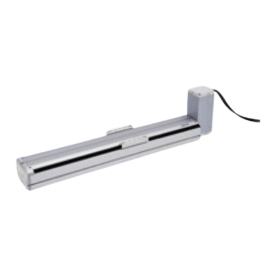
Chapter 3 Axis Specifications ■3.1 Axis type and names of individual parts ■Type of axis The following shows the axis type: KBX-30F-BT-M21N-40 Axis stroke Motor set direction Brake Series name 100 mm Top side mounted 150 mm motor axis 200 mm Right side mounted Frame No. -
Page 15: Single Axis Specification
■3.2 Single axis specification ■ Specifications Type of axis KBX-30-B-N- The values enclosed in parentheses indicate those for the AC 200-watt servo motor. Motor AC 100-watt servo motor absolute) (AC 200-watt servo motor absolute) Drive method Timing belt Lead 21 mm... - Page 16 ■ Axis dimensions (1) Top side mounted motor axis [KBX-30*-BT-***N] Type KBX-30E-BT-M21N-□□ KBX-30F-BT-M21N-□□ KBX-30F-BT-M42N-□□ Stroke X (mm) 1000 1100 1200 1300 1400 1500 1600 1700 1800 1900 2000 2100 2200 2300 2400 2500 2600 2700 2800 2900 3000 3100 3200...
- Page 17 (2) Bottom side mounted motor axis [KBX-30*-BU-***N] Type KBX-30E-BU-M21N-□□ KBX-30F-BU-M21N-□□ KBX-30F-BU-M42N-□□ Stroke X (mm) 1000 1100 1200 1300 1400 1500 1600 1700 1800 1900 2000 2100 2200 2300 2400 2500 2600 2700 2800 2900 3000 3100 3200 Full length L(mm)
- Page 18 (3) Right side mounted motor axis [KBX-30*-BR-***N] Type KBX-30E-BR-M21N-□□ KBX-30F-BR-M21N-□□ KBX-30F-BR-M42N-□□ Stroke X (mm) 1000 1100 1200 1300 1400 1500 1600 1700 1800 1900 2000 2100 2200 2300 2400 2500 2600 2700 2800 2900 3000 3100 3200 Full length L(mm)
- Page 19 (4) Left side mounted motor axis [KBX-30*-BL-***N] Type KBX-30E-BL-M21N-□□ KBX-30F-BL-M21N-□□ KBX-30F-BL-M42N-□□ Stroke X (mm) 1000 1100 1200 1300 1400 1500 1600 1700 1800 1900 2000 2100 2200 2300 2400 2500 2600 2700 2800 2900 3000 3100 3200 Full length L(mm)
-
Page 20: Chapter 4 Cable Installation
Chapter 4 Cable Installation Install the cable according to the following procedure: (1) Loosen the four hexagon socket head button bolts holding the motor cover cap and remove the motor cover cap from the motor cover. Motor cap cover Hexagon socket head button bolt (M4x12) Motor cover Select the cover of the cable outlet in the direction where the cable of the motor cover cap is pulled out, and hold it with cutting pliers. -
Page 21: Chapter 5 Installing Actuator (Axis)
Chapter 5 Installing Actuator (Axis) This chapter describes the basic installation procedures for the axis and peripheral equipment. Installation shall comply with the instructions of this Chapter. If the installation procedure is incorrect, robot performance cannot be achieved. Not only that, the service life may be seriously reduced. CAUTION Precautions for installation ... -
Page 22: Installing Actuator (Axis)
Table are specified in the Actuator Instruction Manual. When you want to use a combination of axes, see the following Table for each an axis. [Robot type for KBX-30] When used as a slider traveling type axis (in normal use) -
Page 23: Parameter Values
■5.3 Parameter values The parameters of this product are available in two types -- parameter 1 and parameter 2 -- depending on the frequency of use. The relationship between each parameter and the robot type is illustrated below: Setting the robot type allows the parameters on the circled portion on the left to be automatically changed. ■5.3.1 Values of parameter 1 for each robot type This parameter has a higher frequency of use. - Page 24 ■5.3.2 Values of parameter 2 for each robot type Belt-driven axis (slider movable type) Robot type 601290 602090 602080 Automatic setting Parameter (100 W, Lead 21) (200 W, Lead 21) (200 W, Lead 42) Axis display 0.05 0.05 0.05 In position data value 20000 20000...
-
Page 25: Chapter 6 Precautions For Use
Chapter 6 Precautions for Use ■6.1 Fluctuation in sliding resistance during long-term storage The belt drive axis of the electric actuator drives the slider by meshing between the timing belt and pulley. When the electric actuator has been stored or its operation has been suspended for a longer period of time (*1), the timing belt is kept curled at the meshing portion between the timing belt and pulley (or roller). -
Page 26: About Cracks On The Back Of The Timing Belt During Long-Term Operation
■6.3 About cracks on the back of the timing belt during long-term operation When the slider part of the belt drive axis reciprocates about 1 million (*1), crack-like streaks occur in the rubber on the back surface (toothless surface) of the timing belt. However, if you are using it within the specifications, there is no problem. -
Page 27: Servo Gain Setting
■6.4 Servo gain setting In the actuator, in order to facilitate the parameter setting work of the controller, the initial parameters for operating the component arm are automatically set by setting the "robot type" (6 digit number) determined for each model to the controller. - Page 28 (2) Speed gain (V) ● When the value is reduced ・ If it is made too small, an error such as "overflow error" may occur during operation (especially when accelerating) and operation may not be possible. ・ The positioning and holding force of the slider is reduced. (Rigidity decreases) ●...
- Page 29 ■6.4.2 About adjustment of servo gain When adjusting the servo gain, refer to the contents described in ■ 6.4.1 "Servo gain setting value and operating condition" and set according to the following description. (1) Speed gain setting The initial value of speed gain usually does not need to be changed. If it is changed, please set as follows.
- Page 30 ● Abnormalities such as vibration and abnormal noise may occur due to resonance, so check the operation from the low speed range used for return to origin operation and "JOG" operation to the high speed range used for continuous operation. ●...
-
Page 31: Chapter 7 Maintenance
Chapter 7 Maintenance ■7.1 Precautions for inspection and maintenance work (1) Precautions for inspection and maintenance work Observe the following instructions at the time of inspection and maintenance: 1. The robot shall be inspected and maintained by the personnel having a sufficient level of skill and experience. If such personnel are not available, contact the manufacturer and request implementation of the relevant work or education of the person in charge. -
Page 32: Inspection Before Starting The Work
■7.2 Inspection before starting the work (1) Before starting your work with the robot, make sure of the following: 1. Brake device function 2. Emergency stop device function 3. Contact preventive equipment and robot interlock function 4. Related devices/robot interlocking function 5. -
Page 33: Greasing
■7.5 Greasing Greasing positions The linear guide of this product are provided with an oilless seal. To prevent a possible accident, check for the greasing conditions and damages on a periodic basis. If insufficient lubrication has been found out, supply grease according to the following steps. -
Page 34: Timing Belt Inspection
■7.6 Timing belt inspection Inspect the timing belt at intervals of approximately 500 hours. Check the belt for deterioration, fatigue and scratches. Replace it if any problem has been detected. For the replacement procedure, see the Actuator Instruction Manual. ... - Page 35 (2) Loosen two belt clamp bolts and reduce the timing belt tension. (This step is not necessary if you want to replace the motor for the 21 mm-lead product alone.) When the motor faces leftward, remove the frame cover mounting plate from the end base and loosen the belt clamp bolt from the hole of the end base.
- Page 36 For 42 mm-lead product Belt clamp proper Loosen the belt clamp mounting screw on the Motor block motor block side and remove the belt clamp proper from the motor block. Belt clamp mounting bolt (6) Remove the screw of the sheet metal fixing the belt of the belt clamp on the motor block side. Then remove the belt.
- Page 37 For 42 mm-lead product Turn back the timing belt within the motor block so that it can be applied to the pulley (See 7.8.2). Timing belt to be formed into a ring CAUTION Do not allow the belt to be twisted. (11) For the 21 mm-lead product, mount the motor spacer on the motor block.
- Page 38 (16) Mount the motor on the motor block, and loosen four bearing clamping plate screws on the bottom of the motor block. Make sure that the bearing clamping plate rotates a little about the bearing. After that, uniformly retighten bearing clamping Bearing fixing plate mounting screws having been loosened.
-
Page 39: Routing The Timing Belt
■7.8 Routing the timing belt For the details of the motor block interior, see Section 7.7 (10). Route the timing belt so that the belt tooth will touch the toothed pulley and the back of the belt will touch the toothless pulley. - Page 40 Left side mounted motor axis (The end side belt clamp is located inside the end base.) End pulley (toothed) Belt clamp (toothless) ) (Inside the motor block) Belt clamp (Inside the end base) Slider block Motor facing leftward Motor block Slider block internal pulley End base Timing belt...
-
Page 41: Origin Position Adjustment
Right side mounted motor axis Slider block internal pulley (toothed) Motor pulley (toothed) ) Slider block (Inside the motor block) Belt clamp Slider block internal pulley (toothless) Motor block End block Belt clamp Timing belt (Inside the motor bracket) End pulley (toothed) Motor facing rightward ... -
Page 42: Linear Guide Replacement
■7.10 Linear guide replacement If the linear guide needs to be replaced, contact our sales office closest to your company. It must not be replaced by the customer. This replacement is performed for each axis. It should be noted that this replacement cannot be made inside the device or in the combined state. -
Page 43: Chapter 8 Spare Parts
Chapter 8 Spare Parts ■8.1 Spare Parts When a trouble has occurred to the robot proper and you have found it out at an earlier stage, you cannot repair it if you have no repair parts. Accordingly, you are recommended to keep spare parts on hand. Parts name Remarks Varies according to the stroke. - Page 44 Jul. 2022...
Need help?
Do you have a question about the KBX-30 and is the answer not in the manual?
Questions and answers