Table of Contents
Advertisement
Quick Links
INSTRUCTION MANUAL
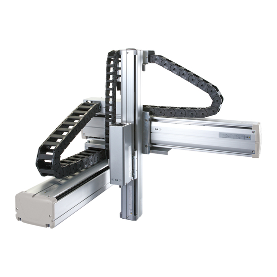
Electric actuator
KBX series
KBX-T5
KBX-T7
Slider type
● Before operating the product, read this
instruction manual without fail.
● Among all, carefully read the description related
to safety.
● Keep this instruction manual in a safe place so
that you can read it at any time when
necessary.
SM-629762-A
2th Edition
CKD Corporation
Advertisement
Table of Contents

Subscribe to Our Youtube Channel
Related Manuals for CKD KBX-T5


Summary of Contents for CKD KBX-T5
- Page 1 SM-629762-A INSTRUCTION MANUAL Electric actuator KBX series KBX-T5 KBX-T7 Slider type ● Before operating the product, read this instruction manual without fail. ● Among all, carefully read the description related to safety. ● Keep this instruction manual in a safe place so that you can read it at any time when necessary.
- Page 2 All efforts have been made to assure the contents of this manual. If you have any questions, or find any mistakes, however, please contact CKD. CKD will not be held responsible for any effects caused by using this equipment, regardless of Item 3 above. The contents of this manual are subject to change without prior notice to effect improvements.
-
Page 3: Table Of Contents
Contents Chapter 1 Safety ................................1 ■1.1 Cautions for safety ............................1 ■1.2 For your safe operation ............................ 5 ■1.3 Warranty ................................9 Chapter 2 Shipment List............................. 10 ■2.1 Shipment list ..............................10 Chapter 3 Axis Specifications ............................ 11 ■3.1 Axis type and names of individual parts ......................11 ■3.2 Single axis specification .......................... -
Page 4: Chapter 1 Safety
Overview • This manual describes the axis type expression method, specifications and motor replacement procedures, etc., according to the type of axis. • For the installation, see the instruction manual (installation of actuator) provided separately. Chapter 1 Safety ■1.1 Cautions for safety ●... - Page 5 WARNING • Install the safety fences to prevent anyone from entering the working envelope of the robot. When the door is attached to the safety fence, the robot should be stopped at emergency at the same time that the door has opened. •...
- Page 6 WARNING • As the equipment is heavy, make sure of its weight and gravity center position and disconnect the cables when carrying the equipment. Also, DO NOT carry the equipment with the slider. Otherwise, the slider will move and you will get injured.
- Page 7 CAUTION • DO NOT place the equipment at a place where the ambient temperature exceeds 40°C, or where the temperature changes sharply, causing condensing, or where it is exposed to direct sunlight. Additionally, if the equipment is installed at a narrow place, the ambient temperature rises due to heat generation in the controller itself or external device, which will result in malfunction or mis-operation of the equipment.
-
Page 8: For Your Safe Operation
■1.2 For your safe operation When you use the electric actuator KBK Series, be sure to take the measures in conformity to the following instruction: This machine is an industrial robot in conformance to the provisions of Paragraph 31of Article 36 of the Ordinance on Industrial Safety and Hygiene. - Page 9 ■1.2.2 Precautions for installation Observe the following instructions when installing a robot: (1) The robot shall be laid out to ensure the work space required for robot teaching, maintenance and inspection. (2) The robot controller, other controllers and stationary operation panel shall be installed outside the movable range and where the operator can watch the robot operations.
- Page 10 (3) Measures to ensure the operation safety of the personnel working within the movable range Any one of the following measures or other measures on the equal or higher level shall be taken so that you can stop the robot operation immediately in the event of an error when working within the movable range: 1.
- Page 11 Requesting your cooperation For the safety instructions which seem especially important, relevant warning label is attached to the equipment. When the label attached to the equipment has peeled off or the characters are defaced and unreadable, please procure it from our sales agent in your territory by specifying the part number, and attach it to the original place.
-
Page 12: Warranty
■1.3 Warranty ■1.3.1 Warranty period This product is warranted for one of the following periods whichever comes first. (1) For 24 months after shipment from our factory. (2) For 18 months after installation at the customer's factory. (3) For 4000 hours of operation. ■1.3.2 Details of warranty (1) This product is warranted. -
Page 13: Chapter 2 Shipment List
Chapter 2 Shipment List ■2.1 Shipment list When the axis proper is shipped, it is composed of the following parts: (1) Actuator (axis) (2) Introduction Manual... -
Page 14: Chapter 3 Axis Specifications
Chapter 3 Axis Specifications ■3.1 Axis type and names of individual parts ■Type of axis The following shows the axis type: KBX-T5D-ST-M12N-40 Series name Ball screw lead Motor set direction 6 mm Straight axis Frame No. 12 mm Size S Size M Axis stroke 50mm... -
Page 15: Single Axis Specification
■3.2 Single axis specification ■ Specifications Type of axis KBX-T5D-ST-M- Motor AC 50-watt servo motor absolute Ball screw 8 Drive method Lead 12 mm Lead 6 mm Guide method Linear guide (Single rail) bearing block ... 1 piece Maximum payload Mass Ball screw lead Horizontal Vertical... - Page 16 Type of axis KBX-T7D-ST-M- Motor AC 50-watt servo motor absolute Ball screw 12 Drive method Lead 12 mm Lead 6 mm Guide method Linear guide (Single rail) bearing block ... 1 piece Maximum payload Mass Ball screw lead Horizontal Vertical (Note 1) (Note 3) 12 mm 12 kg...
- Page 17 ■ Axis dimensions [KBX-T5D-ST-M***] KBX-T5D-ST- KBX-T5D-ST- KBX-T5D-ST- KBX-T5D-ST- KBX-T5D-ST- KBX-T5D-ST- KBX-T5D-ST- KBX-T5D-ST- KBX-T5D-ST- KBX-T5D-ST- Without brake M**N-05 M**N-10 M**N-15 M**N-20 M**N-25 M**N-30 M**N-35 M**N-40 M**N-45 M**N-50 Type KBX-T5D-ST- KBX-T5D-ST- KBX-T5D-ST- KBX-T5D-ST- KBX-T5D-ST- KBX-T5D-ST- KBX-T5D-ST- KBX-T5D-ST- KBX-T5D-ST- KBX-T5D-ST- With brake M**B-05 M**B-10 M**B-15 M**B-20...
- Page 18 [KBX-T7D-ST-M***] KBX-T7D-ST- KBX-T7D-ST- KBX-T7D-ST- KBX-T7D-ST- KBX-T7D-ST- KBX-T7D-ST- KBX-T7D-ST- KBX-T7D-ST- KBX-T7D-ST- KBX-T7D-ST- KBX-T7D-ST- KBX-T7D-ST- KBX-T7D-ST- Without brake M**N-05 M**N-10 M**N-15 M**N-20 M**N-25 M**N-30 M**N-35 M**N-40 M**N-45 M**N-50 M**N-55 M**N-60 M**N-70 Type KBX-T7D-ST- KBX-T7D-ST- KBX-T7D-ST- KBX-T7D-ST- KBX-T7D-ST- KBX-T7D-ST- KBX-T7D-ST- KBX-T7D-ST- KBX-T7D-ST- KBX-T7D-ST- KBX-T7D-ST- KBX-T7D-ST- KBX-T7D-ST-...
-
Page 19: Chapter 4 Installing Actuator (Axis)
Chapter 4 Installing Actuator (Axis) ■4.1 Installing Actuator (Axis) This chapter describes the basic installation procedures for the axis and peripheral equipment. Installation shall comply with the instructions of this Chapter. If the installation procedure is incorrect, robot performance cannot be achieved. -
Page 20: Robot Type For Each Axis
Table are specified in the Actuator Instruction Manual. When you want to use a combination of axes, see the following Table for each an axis. [Robot type for KBX-T5/KBX-T7] When used as a slider traveling type axis (in normal use) -
Page 21: Parameter Values
■4.3 Parameter values The parameters of this product are available in two types -- parameter 1 and parameter 2 -- depending on the frequency of use. The relationship between each parameter and the robot type is illustrated below: Setting the robot type allows the parameters on the circled portion on the left to be automatically changed. ■4.3.1 Values of parameter 1 for each robot type This parameter has a higher frequency of use. - Page 22 ■4.3.2 Values of parameter 2 for each robot type Straight axis (slider movable type) Automatic 600200 600210 600220 600230 Robot type setting Parameter (Lead 6) (Lead 12) (Lead 6) (Lead 12) Axis display 00.05 00.05 00.05 00.05 In position data value 20000 20000 20000...
-
Page 23: Chapter 5 Precautions For Use
Chapter 5 Precautions for Use ■5.1 Servo gain setting In the actuator, in order to facilitate the parameter setting work of the controller, the initial parameters for operating the component arm are automatically set by setting the "robot type" (6 digit number) determined for each model to the controller. - Page 24 (2) Speed gain (V) ● When the value is reduced ・ If it is made too small, an error such as "overflow error" may occur during operation (especially when accelerating) and operation may not be possible. ・ The positioning and holding force of the slider is reduced. (Rigidity decreases) ●...
- Page 25 ■5.1.2 About adjustment of servo gain When adjusting the servo gain, refer to the contents described in ■ 5.1.1 "Servo gain setting value and operating condition" and set according to the following description. (1) Speed gain setting The initial value of speed gain usually does not need to be changed. If it is changed, please set as follows.
- Page 26 ● Abnormalities such as vibration and abnormal noise may occur due to resonance, so check the operation from the low speed range used for return to origin operation and "JOG" operation to the high speed range used for continuous operation. ●...
-
Page 27: Chapter 6 Maintenance
Chapter 6 Maintenance ■6.1 Precautions for inspection and maintenance work (1) Precautions for inspection and maintenance work observe the following instructions at the time of inspection and maintenance: 1. The robot shall be inspected and maintained by the personnel having a sufficient level of skill and experience. If such personnel are not available, contact the manufacturer and request implementation of the relevant work or education of the person in charge. -
Page 28: Inspection Before Starting The Work
■6.2 Inspection before starting the work (1) Before starting your work with the robot, make sure of the following: 1. Brake device function 2. Emergency stop device function 3. Contact preventive equipment and robot interlock function 4. Related devices/robot interlocking function 5. -
Page 29: Adjusting Home Position
■6.4 Adjusting Home Position Adjust the home position in the following manner. (1) Turn the power off. (2) Loosen and remove the two (2) low-head plus screws from the top side of the motor block. Fig. 6.4–1 (3) Remove the stainless sheet and loosen one (1) hexagon socket head cap screw (M2.5) of the coupling connecting the motor and ball screw. - Page 30 (4) Temporarily connect the actuator and controller, connect the teach pendant with the controller, then turn the power on. For how to connect, see Para. 2.5.4 of the instruction manual (basic) provided separately. (5) Set the servo gain values (position and speed) of Parameter 1 to zero (0). For the setting procedures, see Para. 13.3.3,13.3.4 of the instruction manual (basic).
-
Page 31: Changing Home Position
■6.5 Changing Home Position (1) Specify "0" for the motor revolving direction of Parameter 2. (2) Adjust the home position. As in Para. 5.4 above, the position "B" mm away from the end block should be the home point. (See Fig. 6.5–1.) Fig. - Page 32 Before tightening the coupling clamp screw, be sure to turn off the controller power. CAUTION DO NOT shift the motor shaft and coupling from the stopped positions The home position differs between the KBX-T5 and KBX-T7 actuators. (See Fig. 6.6–4.) Fig. 6.6–4 Type of axis...
-
Page 33: Replacing Stainless Sheet
■6.7 Replacing Stainless Sheet To replace the stainless sheet, observe the following procedures. Take careful precautions not to cut your hand by the stainless sheet. CAUTION (1) Remove the four (4) screws securing the stainless sheet, using a screwdriver, and remove the plate. Fig. -
Page 34: Greasing
■6.8 Greasing Greasing procedures • Ball screw and linear guide 1. Turn off the drive power. 2. Remove the screws (4 places) fixing the stainless sheet. 3. Greasing according to the table and figure shown below. Type of grease Inspection and Greasing position Volume of grease (manufacturer) -
Page 35: Replacement Of Ball Screw
■6.9 Replacement of ball screw If the replacement of ball screw needs to be replaced, contact our sales office closest to your company. It must not be replaced by the customer. This replacement is performed for each axis. It should be noted that this replacement cannot be made inside the device or in the combined state. -
Page 36: Chapter 7 Spare Parts
Accordingly, you are recommended to keep spare parts on hand. Part name Remarks For KBX-T5 Stainless sheet For KBX-T7 (Differs with the stroke.) For KBX-T5 and KBX-T7 (commonly used) AC servo motor (encoder: absolute) (50 W) AC servo motor with brake For KBX-T5 and KBX-T7 (commonly used) (encoder: absolute) - Page 37 Jul. 2022...
Need help?
Do you have a question about the KBX-T5 and is the answer not in the manual?
Questions and answers