Table of Contents
Advertisement
Quick Links
Discontinue
INSTRUCTION
MANUAL
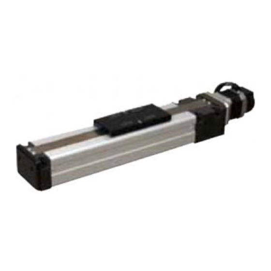
ELECTRIC ACTUATOR
KBZ Series
CONTROLLER
KCA-01-M05
ACTUATOR INSTRUCTION
MANUAL
● Read this manual carefully and thoroughly
before using this product.
● Pay extra attention to the instructions
concerning safety.
● After reading this manual, keep it in a safe
and convenient place.
SM-479504-A
Advertisement
Table of Contents

Related Manuals for CKD KBZ Series


Summary of Contents for CKD KBZ Series
- Page 1 Discontinue SM-479504-A INSTRUCTION MANUAL ELECTRIC ACTUATOR KBZ Series CONTROLLER KCA-01-M05 ACTUATOR INSTRUCTION MANUAL ● Read this manual carefully and thoroughly before using this product. ● Pay extra attention to the instructions concerning safety. ● After reading this manual, keep it in a safe...
- Page 2 Thank you for selecting the Electric Actuator KBZ series. To ensure correct usage, read this instruction manual before starting use of the Electric Actuator KBZ series. For information on the actuators in Electric Actuator KBZ series, refer to the Actuator Operating Manual supplied with the actuator. PRECAUTION 1.
-
Page 3: Table Of Contents
Discontinue Contents Chapter 1 General Safety Instruction ................1 ■ 1.1 Important Safety Information....................1 ■ 1.2 Safe Operation ......................... 6 ■ 1.2.1 Auxiliary safety precautions before robot installation ............6 ■ 1.2.2 Precautions for installing the robot ..................7 ■ 1.2.3 Precautions for operation of the robot ................ - Page 4 Discontinue Chapter 3 Parameter Settings ..................53 ■ 3.1 Entering and Exiting the PARA Mode..................53 ■ 3.2 Mode Setting .......................... 54 ■ 3.2.1 M01 (T/P Japanese/English switching)................55 ■ 3.2.2 M13 (OUT2 Function Selection) ..................55 ■ 3.3 Parameter 1 ........................... 56 ■...
- Page 5 Discontinue ■ 4.2.5 Operation/Teach switching input (IN6) ................98 ■ 4.2.6 + Jog input, - Jog input (IN1, IN2)..................98 ■ 4.2.7 Write input (IN4)........................ 99 ■ 4.2.8 Command point number input (IN7 - IN10)............... 99 ■ 4.2.9 Output during operation (OUT1) ..................99 ■...
-
Page 6: Chapter 1 General Safety Instruction
Discontinue Chapter 1 General Safety Instruction ■ 1.1 Important Safety Information To ensure safe usage of the Electric Actuator KBZ, read this Operating Manual before installation, programming, operation, maintenance, and inspection. After reading this manual, keep it in an easily accessible location, such as near this equipment, where it can be referred to at all times. - Page 7 Discontinue WARNING • A safety fence must be installed to prevent entry into the range of motion of the robot. If a door or other entrance is provided in the safety fence, an emergency stop must be applied to the robot when the door is opened. •...
- Page 8 Discontinue CAUTION • Do not insert your fingers or hands into the openings or moving parts. This can result in an injury. • When using the axis unit at an orientation other than the horizontal mounting, an axis with brake must be used. When the power is turned off, the slider can drop, and this can result in an injury.
- Page 9 Discontinue CAUTION • When using the motor reversal axis in a vertical orientation, perform periodic inspection of the belt, and replace the belt after every 3000 hours of operation. If the belt is used past its lifespan, it can break. This could cause the slider to unexpectedly drop, and result in an injury.
- Page 10 Discontinue <IMPORTANT> Warning labels are affixed to the product body for particularly important safety information. Please make sure the labels do not come off or become illegible. Controller warning label WARNING • To ensure safety, be sure to read the Operating Manual before installation, programming, operation, maintenance, and inspection.
-
Page 11: Safe Operation
Discontinue ■ 1.2 Safe Operation When using the Electric Actuator KBZ series, safety measures must be implemented to satisfy the items below. This equipment corresponds to an industrial robot as stipulated in article 36, item 31 of the Occupational Safety and Health Act regulations. Important safety information when using this equipment is contained in the sections "Selection", "Installation", "Usage", "Periodic Testing", and "Training"... -
Page 12: Precautions For Installing The Robot
Discontinue ■ 1.2.2 Precautions for installing the robot Pay attention to the following points when installing the robot. (1) Allow ample clearance for teaching the robot, maintenance operations and inspection. (2) The robot controller, other control devices must be installed outside the robot's zone of operation, but within easy access of the operator. - Page 13 Discontinue (3) Precautions as needed to assure the safety of personnel in the robot's area of operation To secure the zone of robot operation, take measures such as but not limited to the following. Assign a guard to watch the robot operating area to prevent unauthorized persons from entering the operating zone.
-
Page 14: Warranty
CKD will not be liable for any secondary or incidental damage as a result of breakdowns of this product. (2) During the warranty period of this product, CKD will repair free of charge only breakdowns that occur for operation and usage performed in accordance with the instruction manuals provided with the product. -
Page 15: Notes
(1) CKD cannot guarantee basic performance of this product when it is used under conditions outside the product specifications. (2) CKD is not liable for any accidents, damage, or breakdowns that occur as a result of failing to follow the warning and caution information provided in this instruction manual. -
Page 16: Chapter 2 Overview
Discontinue Chapter 2 Overview ■ 2.1 Features This product is a single-axis robot controller with 24 V DC power supply that has been developed for providing a powerful features in a compact, low-cost design. The main features and functions are shown below. [Features of Axis Unit] Motor sensor with built-in resolver The motor sensor incorporates a brushless resolver as standard for providing superior resistance to... -
Page 17: System Configuration
Discontinue ■ 2.2 System Configuration Battery View from Arrow A Teach pendant Computer Control power supply 駆動電源 Drive power supply 制御電源 Regenerative resistor 回生抵抗 Sequencer and other devices Sensor センサ Motor モータ KBZ axis... -
Page 18: Controller Specifications
Discontinue ■ 2.3 Controller Specifications Item Description Compatible robot Electric Actuator KBZ series Controller model KCA-01-M05 Number of controllable axes 1 axis Motor capacity 50 W Control method Semi-closed loop control Teaching method Remote teaching, Direct teaching or MDI Speed setting... -
Page 19: External Dimensions
Discontinue ■ 2.4 External Dimensions ■ 2.5 Names and Functions of Each Part ■ 2.5.1 Explanation of the controller CN6 battery connector SW1 brake release switch LED1 status LED View from Arrow A SW2 mode setting switch CN3 sensor connector CN5 serial connector CN1 power connector CN4 input/output connector... - Page 20 Discontinue CN6 battery connector This is a connector for connecting the resolver ABS backup battery. For details on the battery connector, refer to section ■ 2.7.8. SW1 brake release switch This is a momentary switch for manually releasing the brake. The brake is manually released while the lever is raised to the up position, and the brake returns to normal brake control when the lever is released.
- Page 21 Discontinue Flashing pattern 0.8 sec 0.4 sec Repeats continuously after this II. Boot mode (SW2 is set to F) Color Status Flashing pattern Boot standby Flashing red + green Boot in progress − Solid green Normal end − Solid red Abnormal end Flashing pattern Flashing pattern...
- Page 22 Discontinue Cable-side connector model Receptacle housing 1-1318118-6 Terminal 1318108-1 Manufacturer Tyco Electronics AMP Row B Row A Controller-side connector model Tab header 1376020-1 Manufacturer Tyco Electronics AMP CN5 serial connector This is an RS-232C connector for connecting the teach pendant (TPH-4C) or the communication cable (PCBL-31) for computer connection.
- Page 23 Discontinue Cable-side connector model Plug 10114-3000PE Shell kit 10314-52A0-008 Manufacturer Controller-side connector model Receptacle 10214-52A2PL Manufacturer CN4 input/output connector This connector consists of system input/output and emergency stop input, and it is connected to a sequencer or other device for performing external control of the robot. For details of the input/output connector, refer to Chapter 4.
- Page 24 Discontinue CN2 motor connector This is a connector for connecting the motor cable. Pin No. Signal name Notes Brake Brake Cable-side connector mode Receptacle housing 5557-06R Terminal 5556TL Manufacturer MOLEX Controller-side connector model Header 5569-06A1 Manufacturer MOLEX...
-
Page 25: Explanation Of The Teach Pendant
Discontinue ■ 2.5.2 Explanation of the teach pendant Emergency stop switch Instruction-word and numeric keys Move keys KCA-TPH-4C ESC key Exits the mode in which processing has been performed with a function key. F1-F4 keys Function keys to perform various types of processing. RUN/PRGM key Switches between RUN mode and PRGM mode. - Page 26 Discontinue HELP key Displays the explanation about the current function key. ALT key Use this key to select a new input item in place of the old one, except for numeric values, in the table and parameter mode. SEARCH key Use this key to search for a parameter number, table number, or error number.
- Page 27 Discontinue Shown below is the operation system diagram of the teach pendant. [RUN mode] T/P ON Override Power ON Monitor Extension Monitor Page Robot type Error history display Version T/P ON Memory initialization T/P OFF PRGM mode Clear Memory initialization Point table Parameter mode Set mode...
-
Page 28: Connections
Discontinue ■ 2.6 Connections Please wire to KCA-01-M05 as shown below. KCA-01-M05 Regenerative resistor Teach pendant 24 V (*2) power Regenerative resistor Noise Computer MCCB supply filter KBZ axis Control power supply Sensor cable 100 V AC/ 200 V AC Drive power supply Sequencer and other devices... -
Page 29: Procedures From Installation To Operation
Discontinue ■ 2.7 Procedures from Installation to Operation The procedures for installing the robot to operating the robot are as follow. Reference page 1) Selecting the power supply ····················································································· Section ■ 2.7.1 2) Installing the axis··················································································· Axis unit instruction manual 3) Installing the controller ····························································································... -
Page 30: Selecting The Power Supply
Discontinue ■ 2.7.1 Selecting the power supply The power supplies for this controller are as shown in the following table. Note that, if capacity of the drive power supply is insufficient, low power output, low torque, and other problems can occur that prevent full performance during operation. -
Page 31: Installing The Controller
Discontinue ■ 2.7.2 Installing the controller The controller uses a natural cooling method through convection. When installing the controller, place it in the vertical orientation as shown in the figure below, and leave a space of at least 10 mm right and left, 50 mm above and below it. -
Page 32: Supply Power And Grounding
Discontinue ■ 2.7.3 Supply power and grounding The power supply cable of the controller is connected as shown below. Power supply connector wiring procedure Peel off the covering of the wires. Uncovered wire length: 6 to 7 mm Open the wire terminal pockets of the power supply connector. -
Page 33: Power Supply On/Off Timing
Discontinue ■ 2.7.4 Power supply on/off timing Note: If this timing is not observed for shutting off the control power supply and drive power supply, the vertical axis can drop by up to about 5 mm. Control power supply Drive power supply Servo on input (IN3) READY/Error output 1 sec or... -
Page 34: Improvement Of Noise Resistance
Discontinue ■ 2.7.5 Improvement of noise resistance Using the following measures to further improve the noise resistance is recommended. Insert a power line insulation transformer (1:1) or noise filter. Insulation To controller input connectors 24 V of control power supply and transformer power supply... -
Page 35: Setting The Robot Type
Discontinue ■ 2.7.6 Setting the robot type Setting the robot type enables automatic setting of various parameter values for the axes that are used. Setting range : 000000 to 999999 Initial value : 700000 For the robot type values, refer to the actuator instruction manual. When the robot type is changed, the parameters in the table below are automatically set. - Page 36 Discontinue Set the robot type according to the following procedure: The initial display is shown for two seconds after the STEP 1 T O S H I B A M A C H I N E [PRGM] power is turned on. T E A C H I N G P E N D A N T 0001 * The display format and version vary depending on...
-
Page 37: Servo Gain Adjustment
Discontinue ■ 2.7.7 Servo gain adjustment There are two kinds of gain in the servo mechanism of this Electric Actuator KBZ: position gain (P03) and speed gain (P04). They are set through parameter 1. Generally, a larger servo gain enables higher speed response in the servo mechanism and a smaller servo gain enables smooth movement of the Electric Actuator KBZ. -
Page 38: Resolver Abs Backup
Discontinue ■ 2.7.8 Resolver ABS backup All models of the KBZ axis AC servomotor include a resolver ABS. The power is driven by a battery to enable constant monitoring of motor operation even when the power supply to the controller is cut off and to allow smooth startup without returning to the origin when starting the system and recovering from an emergency stop. - Page 39 Discontinue Backup specification Item Specification Remarks Controller front LED flashes in orange when at 3.1 V DC or less (low voltage warning) Backup voltage 3.6 V DC (Standard) Battery error occurs at 2.5 V DC or less (Note 1) When controller is in 260 μA (Maximum) 25°C non conducting state...
-
Page 40: Regenerative Resistors
Discontinue ■ 2.8 Regenerative Resistors Regenerative resistors are devices that absorb the energy generated when the axis unit motor is decelerated. These are used when the load inertia exceeds the allowable value or when a large load descends down a long stroke (generating a large amount of power) along the Z-axis. (The regenerative resistor prevents an overvoltage from occurring in the controller.) * A resistor type (KCA-CAR-0500) and a unit type (KCA-CAR-UN50) are available. -
Page 41: External Dimensions
Discontinue ■ 2.8.2 External dimensions KCA-CAR-0500 KCA-CAR-UN50 60±1.5 5.3±0.3 4.2±0.2 5.3±0.3 接続コネクタ Connector 4.2±0.2 ■ 2.8.3 Installation The regenerative resistors uses a natural cooling system based on convection currents. When installing the regenerative resistors, install it standing vertically as shown in the figure, and provide at least 10 mm of space on the right and left sides and at least 50 mm of space at the top and bottom. -
Page 42: Connection Example
Discontinue ■ 2.8.4 Connection example Connect the controller and power supplies to the regenerative resistor as shown below. Controller コントローラ 1 Drive power 駆動電源 supply DC24V 2 24 V DC 3 Control power 制御電源 CN1 supply 24 V DC DC24V 4... - Page 43 Discontinue Connection terminal KCA-CAR-0500 KCA-CAR-UN50 Front View Bottom View Pin No. Name Resistor 2 Resistor 1 Resistor 2 Temperature relay 1 Temperature relay 2 Temperature relays 1 and 2 Resistor 1 * If the length of the output lines of the temperature relay is not enough, use by connecting the supplied relay connector.
-
Page 44: Basic Knowledge
Discontinue ■ 2.9 Basic Knowledge ■ 2.9.1 Let's begin moving the robot. Enter a simple program to move the robot. The following explains items 11-16 in section ■ 2.7: 11) Setting a software limit In order to prevent the robot from overrunning, a software limit is to be set for the machine to limit the axis travel range. -
Page 45: Setting The Point Table
Discontinue 14) Setting a point table The following is an example of setting to move the robot 100 mm in the positive direction from the origin. Check that the PRGM mode is active, and press the STEP 1 [ P R G M ] N O R M A L [PRGM] key. -
Page 46: Jog Operation (Axis Operation In Manual Mode)
Discontinue ■ 2.9.2 Jog operation (axis operation in manual mode) Jog operation is operating an axis in remote mode. Use jog operation when stopping the automatic operation and moving an axis or when moving an axis during the editing of a point table. Particularly, if an axis having a brake is used, the brake is applied when the servo lock is freed, and the axis cannot be moved. -
Page 47: Entering Coordinate Values
Discontinue STEP 3 For example, the axis moves while the key is [ P R G M ] N O R M A L [PRGM] held down. P N T - T B L X 1 = 0 0 0 0 . 0 0 0001 N O 0 0 1 V = 1 A = 5 D = 5... - Page 48 Discontinue Remote teaching cannot be performed when the cursor is not at the above position. NOTE DIRECT If the key is pressed when the cursor is not at the above position, jog operation to simply move the axis is performed. (Refer to section ■ 2.9.2.) DIRECT If no origin return has been performed, the error buzzer bleeps when the key is...
- Page 49 Discontinue Direct teaching cannot be performed when the cursor is not at the above position. NOTE FREE When the key is pressed, an axis having a brake is braked. LOCK DIRECT If no origin return has been performed, the error buzzer bleeps when the key is pressed, and the direct teaching mode cannot be activated.
-
Page 50: Setting The Override
Discontinue ■ 2.9.4 Setting the override The override function can be used to slow down the overall movement speed. This can allow operation checks at device startup at low speed, for instance. However, note that the override function is disabled during jog operation, low-speed origin return, and medium-speed origin return. - Page 51 Discontinue (1) Performing Clear All Memory through the PRGM (program) mode Activate the PRGM (program) mode, and press the key. HELP The following screen will be displayed: In this condition, press the key. STEP 1 [ P R G M ] F 1 : [PRGM] H E L P F 2 :...
- Page 52 Discontinue (2) Performing Clear All Memory without turning on the teach pendant (T/P ON) after the power is turned This machine can perform Clear All Memory without turning T/P ON after the power is turned on. If Clear All Memory cannot be performed through the PRGM mode when an error occurs, use the following method to clear the memory: The initial display is shown for two seconds after the STEP 1...
-
Page 53: Monitor Function
Discontinue ■ 2.9.6 Monitor function A function is provided for monitoring the controller and axis states. The parameters that can be monitored are shown below. X1 (*1): Coordinate value (mm) SP: Speed (mm/s) MR: Motor rotational speed (rpm) CR: Current (A rms) DC: Deviation counter (pulses) EL: Execution loading ratio (%) DF: Driving force (N) - Page 54 Discontinue STEP 4 In page 2/3, the following can be monitored: [ M O N I ] D C = 0 0 0 0 0 0 0 p l s [PRGM] DC: Deviation counter (pulses), EL: Execution loading E L = 0 0 0 % 0001 D F = 0 0 0 0 0 N ratio (%), and DF: Driving force (N)
-
Page 55: Turning On/Off The Teach Pendant
Discontinue ■ 2.9.7 Turning on/off the teach pendant This machine can logically disconnect the teach pendant through the following operation even while the teach pendant is connected, thus enabling system input. Turning off the teach pendant Activate the RUN mode, and press the key to STEP 1 HELP... -
Page 56: Displaying The Versions
Discontinue ■ 2.9.8 Displaying the versions The versions of the controller and teach pendant can be displayed on the screen. The initial display is shown for two seconds after the STEP 1 T O S H I B A M A C H I N E [PRGM] power is turned on. - Page 57 Discontinue This page is intentionally left blank...
-
Page 58: Parameter Settings
Discontinue Chapter 3 Parameter Settings The parameters in this controller can be broadly divided into the four types below. Type Parameter No. Description Refer to Section Mode setting M01 to M19 This contains the parameters for the entire system. ■ 3.2 This contains the axis parameters for settings that are changed Section Parameter 1... -
Page 59: Mode Setting
Discontinue ■ 3.2 Mode Setting The mode setting contains the parameters for the entire system. Parameter No. Parameter Setting range Initial value Units Refer to 0, 1 T/P Japanese/English switching Section ■ 3.2.1 00 ~ 99 IN1 function selection 00 ~ 99 IN2 function selection IN3 function selection 00 ~ 99... -
Page 60: M01 (T/P Japanese/English Switching)
Discontinue ■ 3.2.1 M01 (T/P Japanese/English switching) This parameter selects the T/P display language. Enter 0 (display in Japanese) or 1 (display in English) STEP 1 M 0 1 [PRGM] using the numeric keys, and press the key. D I S P L A Y 0 : J A P A N E S E 0001 Pressing the... -
Page 61: Parameter 1
Discontinue ■ 3.3 Parameter 1 Parameter 1 contains the axis parameters for settings that are changed relatively frequently. Parameter Initial Robot type Parameter Setting range Units Refer to value (*1) Section ■ + Software limit -8000.00 to +8000.00 0.00 3.3.1 Section ■... -
Page 62: P01 (+ Software Limit)
Discontinue ■ 3.3.1 P01 (+ Software limit) This indicates the maximum value of the robot movable range. Enter the coordinate value using the numeric keys, and STEP 1 P 0 1 [PRGM] press the key. + S O F T W A R E L I M I T 0001 Pressing the key displays the next screen. -
Page 63: P03 (Servo Gain (Position))
Discontinue ■ 3.3.3 P03 (Servo Gain (Position)) If the setting value is too small for the position gain of the servo system, the positioning time becomes longer. If the setting value is too large, hunting (vibration) occurs. Enter the servo gain using the numeric keys, and press STEP 1 P 0 3 [PRGM]... -
Page 64: P05 (Origin Offset)
Discontinue ■ 3.3.5 P05 (Origin Offset) If the robot coordinates were shifted in parallel from the coordinates that were taught due to replacement of the motor, ball screws, or other components, origin offset can be used to return to the original position. Enter the coordinate value of origin offset using the STEP 1 P 0 5... -
Page 65: P06 (Jog Speed (Low))
Discontinue ■ 3.3.6 P06 (Jog Speed (Low)) This indicates the low-speed movement speed during jog operation. Enter the jog speed (low speed) using the numeric keys, STEP 1 P 0 6 [PRGM] and press the key. 0001 J O G S P E E D ( L O W ) Pressing the key displays the next screen;... -
Page 66: Parameter 2
Discontinue ■ 3.4 Parameter 2 Parameter 2 contains the axis parameters for settings that are changed less frequently than Parameter 1. After these parameters are changed, the control power and drive power must be turned off and then on again. The parameters will not be enabled unless the control power and drive power are turned off. - Page 67 Discontinue Activate the PARA mode to set Parameter 2. (Refer to section ■ 3.1.) In this condition, press the key. STEP 1 [ P A R A ] F 1 : S E T M O D E [PRGM] F 2 : P A R A M E T E R 1 0001 F 3 : P A R A M E T E R 2 F 4 : T A B L E...
-
Page 68: K01 (Axis Display)
Discontinue ■ 3.4.1 K01 (Axis Display) The axis display is the title of the axis displayed on the teach pendant. Select a target alphabetic character (X, Y, Z, R, ?) with STEP 1 K 0 1 [PRGM] key, and press the key. -
Page 69: K03 (Overflow Data)
Discontinue ■ 3.4.3 K03 (Overflow Data) When the value of the deviation counter (deviation between the target position and current position) reaches or exceeds this value, a positional deviation exceeded error occurs. Enter the overflow data using the numeric keys, and STEP 1 K 0 3 [PRGM]... -
Page 70: K05 (Maximum Speed)
Discontinue ■ 3.4.5 K05 (Maximum Speed) This indicates the movement speed limit value. If the setting for the movement speed is set higher than this value, a speed limit is applied. Enter the maximum speed using thenumeric keys, and STEP 1 K 0 5 [PRGM] press the... -
Page 71: K07 (Middle Return Home Speed)
Discontinue ■ 3.4.7 K07 (Middle return home speed) This indicates the movement speed (medium speed) during the origin return operation. Enter the medium origin-return speed using the numeric STEP 1 K 0 7 [PRGM] keys, and press the key. 0001 M I D D L E R T N H O M E S P D Pressing the key displays the next screen;... - Page 72 Discontinue [Explanation of Origin Return Speed] The robot has four origin return methods, and these are divided into two procedures: Initial origin return after power is turned on (start from origin return speed M) and origin return on the second time and after (start from origin return speed H).
-
Page 73: K09 (Return Home Method)
Discontinue ■ 3.4.9 K09 (Return home method) This indicates the sequence during the origin return operation. Enter the origin return method (0-3) using the numeric STEP 1 K 0 9 [PRGM] keys, and press the key. R T N H O M E M E T H O D 0001 Pressing the key displays the next screen;... -
Page 74: K10 (Home Sensor Logic)
Discontinue ■ 3.4.10 K10 (Home Sensor Logic) This selects if the output signal of the origin sensor incorporated in the axis turns OFF (NC) or ON (NO). Enter the origin sensor logic (0 or 1) using the numeric STEP 1 K 1 0 [PRGM] keys, and press the... -
Page 75: K12 (Lead)
Discontinue ■ 3.4.12 K12 (Lead) This indicates the distance that is advanced per motor revolution. Enter the axis lead using the numeric keys, and press STEP 1 K 1 2 [PRGM] key. L E A D 0001 Pressing the key displays the next screen; NEXT A 0 = 0 1 2 . -
Page 76: K14 (Multiplier)
Discontinue ■ 3.4.14 K14 (Multiplier) This indicates the multiplier factor for generating the pulses of the sensor installed on the motor. This is disabled in this controller. STEP 1 Enter the multiplier factor using the numeric keys, and K 1 4 [PRGM] 0001 M U L T I P L I E R... -
Page 77: Tables
Discontinue ■ 3.5 Tables This controller has five types of tables available. Parameter No. Type Number of tables Refer to Point table 15 (No.1 to 15) Section ■ 3.5.1 Speed table 8 (No.1 to 8) Section ■ 3.5.2 Acceleration/deceleration table 8 (No.1 to 8) Section ■... -
Page 78: T01 (Point Table)
Discontinue ■ 3.5.1 T01 (Point Table) A total of 15 point tables are available, numbered from 1 to 15, and they are selected by command point number input (IN7 – IN10) when activated by system input operation. One point table consists of 12 different types of data including coordinate value, speed table number, and other data. - Page 79 Discontinue STEP 1 The screen as shown here appears following the initial P O W E R F 1 : T / P O N [PRGM] display after the power is turned on. In this condition, - O N F 2 : 0001 press the key.
- Page 80 Discontinue (2) Coordinate value Enter the coordinate value (X1) using the numeric keys, STEP 1 [ P R G M ] N O R M A L [PRGM] and press the key. P N T - T B L X 1 = 0 0 0 0 . 0 0 0001 * "X1"...
- Page 81 Discontinue (3) Speed table number Enter the speed table number (V) using the numeric STEP 1 [ P R G M ] N O R M A L [PRGM] keys, and press the key. P N T - T B L X 1 = 0 0 0 0 . 0 0 0001 N O 0 0 1 V = 1 A = 5 D = 5...
- Page 82 Discontinue (6) Area output table number Enter the area output table number (AT) using the STEP 1 [ P R G M ] N O R M A L [PRGM] numeric keys, and press the key. P N T - T B L X 1 = 0 0 0 0 . 0 0 0001 N O 0 0 1 V = 1 A = 5 D = 5...
- Page 83 Discontinue If normal operation (NORMAL) is selected in "(1) STEP 2 [ P R G M ] A G I N G = O F F [PRGM] Operation method," select the aging operation (AGING) P N T - T B L T M = 0 . 0 0 0 0001 option (valid (ON) or invalid (OFF)) with the key,...
- Page 84 Discontinue {1} If normal operation (NORMAL) is selected in "(1) Operation method:" (9) Timer value Enter the timer value (TM) using the numeric keys, and STEP 1 [ P R G M ] A G I N G = O F F [PRGM] press the key.
- Page 85 Discontinue {2} If torque limit operation (TORQUE LIMIT) is selected in "(1) Operation method:" (8) Torque limit table number Enter the torque limit table number (TT) using the STEP 1 [ P R G M ] T T = 8 [PRGM] numeric keys, and press the key.
- Page 86 Discontinue (9) Torque limit judgement time Enter the torque limit judgement time (TM) using the STEP 1 [ P R G M ] T T = 8 [PRGM] numeric keys, and press the key. P N T - T B L T M = 0 . 0 0 0 0001 N O 0 0 1 T A = 0 0 0 .
- Page 87 Discontinue (10) Torque limit movement amount Enter the torque limit movement amount (TA) using the STEP 1 [ P R G M ] T T = 8 [PRGM] numeric keys, and press the key. P N T - T B L T M = 0 . 0 0 0 0001 N O 0 0 1 T A = 0 0 0 .
- Page 88 Discontinue Select the torque limit end (TE) option (valid (ON) or STEP 1 [ P R G M ] T E = O F F [PRGM] invalid (OFF)) with the key, and press the P N T - T B L L E = O F F 0001 key.
-
Page 89: T02 (Speed Table)
Discontinue ■ 3.5.2 T02 (Speed Table) A total of eight speed tables are available, numbered from 1 to 8. They are selected "(3) Speed table number" in the point table (T01). The speed during operation is the value specified by a speed table. Select a target speed table by pressing the key on the table selection screen in STEP2 of section ■... -
Page 90: T03 (Acceleration/Deceleration Table)
Discontinue ■ 3.5.3 T03 (Acceleration/Deceleration Table) A total of eight acceleration/deceleration tables are available, numbered from 1 to 8. They are selected "(4) Acceleration table number" or "(5) Deceleration table number" in the point table (T01). The acceleration (deceleration) time during operation is the value specified by a acceleration/deceleration table. Select a target acceleration/deceleration table by pressing the key on the table selection screen in STEP2 of section ■... -
Page 91: T04 (Torque Limit Table)
Discontinue The acceleration/deceleration tables are stored in the EEPROM. The EEPROM write count NOTE limit is 1 million. Because reading and writing may be unable to be performed normally if the number of writes exceeds 1 million, set the writes to the minimum count necessary. ■... - Page 92 Discontinue (1) Torque limit value (T.LMT) During torque limit operation, Torque limit value = Motor maximum torque (2) Load output standard value (L.STD) If the output torque exceeds the load output standard value for the torque limit judgement time or longer, the load output (OUT6) is set to ON.
-
Page 93: T05 (Area Output Table)
Discontinue ■ 3.5.5 T05 (Area Output Table) A total of eight area output tables are available, numbered from 1 to 8. Each area output table consists of four types of data: Coordinate value 1 (P1), Coordinate value 2 (P2), Comparison condition, and Output logic. - Page 94 Discontinue Data Configuration in Area Output Table Data Setting range Initial value Units (1) Coordinate value 1 (P1) -8000.00 to +8000.00 0.00 (2) Coordinate value 2 (P2) (3) Comparison condition <=<= / <= / >= <=<= (4) Output logic The area output tables are stored in the EEPROM. The EEPROM write count limit is 1 NOTE million.
- Page 95 Discontinue (4) Output logic This specifies the output logic to the area output (OUT4) when the condition is met. 0: Output OFF when condition is met, Output ON when condition isn’t met 1: Output ON when condition is met, Output OFF when condition isn’t met [Setting example] (1) Coordinate value 1 (2) Coordinate value 2...
- Page 96 Discontinue This page is intentionally left blank...
-
Page 97: Chapter 4 Connection With External Devices
Discontinue Chapter 4 Connection with External Devices ■ 4.1 Input/Output Signals The input/output connector (CN4) consists of a system input/output and emergency stop input for connecting to a sequencer or other device for use in external control of the robot. ■... -
Page 98: Emergency Stop Input
Discontinue ■ 4.1.2 Emergency stop input This is an input for setting the controller to an emergency stop state. When this circuit is not connected, the controller is set to an emergency stop. Emergency stop input +24 V Remote operation emergency stop switch 3.3 kΩ... -
Page 99: System Output
Discontinue ■ 4.1.4 System output System output consists of 8 outputs, numbered from OUT1 to OUT8. Each output function is different during normal operation and during torque limit operation. Operation mode Operating status (*1) Teaching status (*2) Control mode During normal operation (*3) During torque limit operation (*3) -... -
Page 100: Input/Output Signal Connection Example
Discontinue ■ 4.1.5 Input/Output signal connection example + COM System input OUT1 OUT2 OUT3 OUT4 OUT5 OUT6 OUT7 OUT8 OUT9 OUT10 IN10 - COM 24 V DC + COM System output OUT1 OUT2 OUT3 OUT4 OUT5 OUT6 OUT7 OUT8 - COM Sequencer or other device Emergency stop input +24 V... -
Page 101: System Input/Output Signals
Discontinue ■ 4.2 System Input/Output Signals The input signals of the controller use a 10 msec filter for preventing malfunctions due to chattering, noise, or other causes. Once an input signal is switched, a period of 10 msec elapses before the controller recognizes the switching of the input signal. - Page 102 Discontinue Before shutting off the control power supply and drive power supply, set this input to OFF, and allow at least 1 second to elapse. If the control power supply and drive power supply are shut off while this input is set to ON, the vertical axis can drop up to about 5 mm.
-
Page 103: Error Reset Input (In5)
Discontinue ■ 4.2.4 Error reset input (IN5) Signal name: ALRST This is an input that resets an error state. This signal can be received only when the controller is stopped (when it is not operating). ■ 4.2.5 Operation/Teach switching input (IN6) Signal name: RTSEL This is an input that switches between Operating status and Teaching status. -
Page 104: Write Input (In4)
Discontinue ■ 4.2.7 Write input (IN4) Signal name: WRITE This is an input for writing the coordinate value to the point table (T01). The coordinate value cannot be written before completion of origin return. An attempt to write it causes an error indicating that origin return is incomplete. The write input is invalid while T/P ON is selected on the teach pendant, or while operation or parameter transfer is being performed through the computer software (SF-98D). -
Page 105: Error Output (Out2)
Discontinue ■ 4.2.10 Error output (OUT2) Signal name: ERROR This signal is ON when an error occurs in the controller. For details on the error types and their troubleshooting procedures, refer to section ■ 6.2. The function of OUT2 is selected by the parameter M13. (Refer to section ■ 3.2.2.) Normal Error occurs Normal... -
Page 106: Positioning Complete Output (Out3)
Discontinue ■ 4.2.12 Positioning complete output (OUT3) Signal name: POSI This is a signal that indicates that the target position was reached and positioning was completed. This is in the OFF state after the control power supply and drive power supply are turned on and before the origin return operation is completed. -
Page 107: Torque Limit Operation Output (Out5)
Discontinue ■ 4.2.15 Torque limit operation output (OUT5) Signal name: TQCON This is ON during the torque limit operation. (Section A in the figure below) This output is valid only during torque limit operation. A different signal is output during normal operation. -
Page 108: Limit Output (Out7)
Discontinue ■ 4.2.17 Limit output (OUT7) Signal name: TQLIM This is ON when the torque limit continues for the Torque limit judgement time or longer (section ■ 3.5.1 – (9)). This is set to OFF if the output torque drops below the torque limit value even after if it was set to ON momentarily. -
Page 109: Chapter 5 Operation
Discontinue Chapter 5 Operation This chapter describes the robot operating procedures using system input. Robot operation and system output are the same when the robot is operated by the teach pendant and computer software (SF-98D). ■ 5.1 Normal Operation ■ 5.1.1 Moving to target position Example: Moving to point table 3 when stopped at point table 2 (3) 10 msec or longer Point table 2... -
Page 110: Deceleration Stop During Movement
Discontinue Point table 3 setting example (Refer to section ■ 3.5.1) Other input signals Signal Item Symbol Setting value Function State name NORMAL (Normal (1) Operation method Stop input operation) (2) Coordinate value X1(*1) 300.00 [mm] Servo on input 100.0 (3) Speed table number Error reset input [mm/sec] ) - Page 111 Discontinue Movement is started when the start input (IN1) is received. At the same time, the completion point number outputs (OUT5 - OUT8) are all set to ON(=1111). Also, output during operation (OUT1) is set to ON, and the positioning complete output (OUT3) is set to OFF.
-
Page 112: Torque Limit Operation
Discontinue ■ 5.2 Torque Limit Operation Torque limit operation moves the robot to the temporary target position without torque limit, and subsequently moves it to the final target position in the same direction, with specified torque limit. There are two methods to end torque limit operation: one method ends it through an external signal, and the other ends it automatically. - Page 113 Discontinue Point table 3(=0010) is specified by command point number input (IN7 - IN10). Before setting start input (IN1) to ON, check that the output during operation (OUT1) is OFF and the error output (OUT2) is OFF. If OUT2 is assigned to READY/Error output, check that it is ON. Set start input (IN1) to ON after at least 10 msec has elapsed from (1).
- Page 114 Discontinue Point table 3 setting example (Refer to section ■ 3.5.1) Other input signals Signal Item Symbol Setting value Function State name TORQUE LIMIT Servo on input Operation method (Torque limit Error reset input operation) Operation/Teach switching Coordinate value X1(*1) 400.00 [mm] input Speed table number...
-
Page 115: Ending Torque Limit Operation Automatically
Discontinue ■ 5.2.2 Ending torque limit operation automatically This is a method for ending the torque limit operation automatically by the controller. In the controller, detect that the torque limit operation has ended by setting the output during operation (OUT1) to OFF. Determine whether a workpiece is present using the status of the positioning complete output (OUT3), limit output (OUT7), and output during locking (OUT8). - Page 116 Discontinue Movement is started when the start input (IN1) is received. At this point, the torque limit is not activated. At the same time, the output during operation (OUT1) is set to ON, positioning complete output (OUT3) is set to OFF, and the torque limit operation output (OUT5) is set to ON. After the output during operation (OUT1) is set to ON, return the start input (IN1) to OFF, or return it to OFF after at least 10 msec has elapsed after the start input (IN1) was set to ON.
- Page 117 Discontinue Point table 3 setting example (Refer to section ■ 3.5.1) Other input signals Signal Item Symbol Setting value Function State name TORQUE LIMIT Stop input Operation method (Torque limit Servo on input operation) Coordinate value X1 (*1) 200.00 [mm] Error reset input Operation/Teach switching Speed table number...
-
Page 118: Origin Return
Discontinue ■ 5.3 Origin Return If the start input (IN1) is set to ON(=1111) when the command point number inputs (IN7 - IN10) are all set to ON, the origin return operation is started. (1) During initialization (max. 3 sec) Control power supply and drive power supply (5) 10 msec or longer Command point number input (IN7 - IN10) -
Page 119: Jog Operation
Discontinue ■ 5.4 Jog Operation To perform jog operation, set the Operation/Teach switching input (IN6) to ON to switch to Teaching status. Example 1: Jog movement in + direction Operation/Teach switching input (IN6) + Jog input (IN1) - Jog input (IN2) Output during operation (OUT1) ②... - Page 120 Discontinue Example 2: Jog inching movement in the + direction (For fine adjustment) Operation/Teach switching input (IN6) + Jog input (IN1) - Jog input (IN2) Output during operation (OUT1) Error output (OUT2) Positioning complete output (OUT3) Jog inching movement amount Speed Set the Operation/Teach switching input (IN6) to ON to switch to Teaching status.
-
Page 121: Writing Coordinate Values To The Point Table
Discontinue ■ 5.5 Writing Coordinate Values to the Point Table This controller can change the data of the coordinate values in the point table (T01) by the system input/output signals. Example: When writing the current coordinates to the coordinate value of point table 1 Operation/Teach switching input (IN6) Point table 1 ****... -
Page 122: Chapter 6 Errors
Discontinue Chapter 6 Errors When an error is detected, the controller changes to Fault status, and a servo off is used to stop the robot. If an error is detected, check the details/cause of the error according to the error list and take proper action to eliminate the error cause. - Page 123 Discontinue (4) Error history Checking method Description Refer to Section 1 Teach pendant The past 16 errors can be viewed in the history. ■ 6.1 2 Computer software (SF-98D) The past 16 errors can be viewed in the history. If more than one errors occur, the first-detected error is displayed. All the errors are cleared by setting the error reset input to ON.
-
Page 124: Error History Display
Discontinue ■ 6.1 Error History Display The 16 errors most recently occurred can be displayed. Activate the RUN mode, and press the key to HELP STEP 1 [ R U N ] F 1 : [PRGM] display this screen. 0001 H E L P F 2 : O V E R R I D E Pressing the... -
Page 125: Error Code List
Discontinue ■ 6.2 Error Code List Error Error name State Primary cause Remedy code Incompatible Occurs when T/P was An incompatible type of T/P was Check the T/P and controller controller connected to the controller connected to the controller model, and use the correct type Occurs only when power is Controller failure Replace controller... - Page 126 Discontinue Error Error name State Primary cause Remedy code Insufficient power capacity Insufficient regenerative Add regenerative protection performance circuits to power supply Occurs during operation (Drive voltage has exceeded 55 V Insufficient regenerative Over voltage or more) protection performance Lower the deceleration Occurs when power is Controller breakdown Replace controller...
- Page 127 Discontinue This page is intentionally left blank...
-
Page 128: Chapter 7 Maintenance And Inspection
Discontinue Chapter 7 Maintenance and Inspection ■ 7.1 Procedures Before and After Inspection and Maintenance (1) Before inspection and maintenance Be sure maintenance and inspection personnel are adequately trained. If none of your personnel has adequate training, ask your manufacturer's representative to carry out inspection and maintenance or to train your personnel. -
Page 129: Inspection Before Operation
Discontinue ■ 7.2 Inspection Before Operation (1) Check the following before operation: Braking device performance Emergency stop device performance Interlock device between bumpers and the Electric Actuator KBZ Interlock devices between the Electric Actuator KBZ and auxiliary devices External cables and piping for damage Power source voltage, hydraulic oil pressure and pneumatic pressure Electric Actuator KBZ movement Presence of abnormal sound or vibration...
Need help?
Do you have a question about the KBZ Series and is the answer not in the manual?
Questions and answers