
Related Manuals for Patiowell T-PS1268S0BN-1A


Summary of Contents for Patiowell T-PS1268S0BN-1A
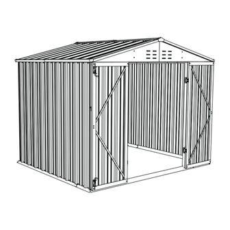
- Page 1 ASSEMBLY INSTRUCTIONS METAL GARDEN SHED SKU: T-PS1268S0BN-1A T-PS1268S0BN-2A YOUR Metal Garden Shed LIFE BUILDER Installation Tutorial https://www.patiowell.com/ pages/video-t-ps1268s0bna www.patiowell.com saleservice@patiowell.com...
- Page 2 SITE PREPARATION Level the ground surface. Recommendation: Construct a wooden or concrete base as a foundation. The external dimensions of the product : 76.2’’ 71.5’’ 89.8’’...
- Page 3 Requires two people and takes 3 hours for Installation. Recommended to wear gloves to avoid scratches. Please read the manual carefully before installation. DO NOT RETURN YOUR UNIT TO THE STORE Contact us first saleservice@patiowell.com...
- Page 4 ROOF PARTS A3 X2 A4 X2 C4R X2 C4L X2 C5 X4 GC X4 GE X2 M2 X4 M2L X4 M9 X2 M10 X2 M11 X4 M13 X2 PE3 X2 PE4 X4 PE5 X2 PE6 X2...
- Page 5 WALL PARTS W1A X12 WS2A X4 WS3A X2 ULA X1 C2 X4 BE1 X1 GS X2 BE2 X1 GR X2 UE1 X1 V1 X50 UE2 X1 UR1 X1 V2 X309 BS3 X2 BE1L X1 BE2L X1 BS3L X2 UE1L X1 UE2R X1 US3 X4...
- Page 6 DOOR PARTS 20 X4 DC X2 DG X1 DH X4 DLA X1 DRA X1 DF X1 DX2 X4 SCREW inch inch F1(X343) M4*10 F2(X44) M4*10 inch inch F3(X32) M5*12 F4(X5) M6*10 For GC inch F5(X4) M4*16...
- Page 7 UE2R UE1L WS2A WS2A WS2A WS3A WS3A WS2A BS3L BE2L BE1L BS3L...
- Page 8 CONTENTS Bottom frame construction 09-12 (page) Wall construction 13-24 (page) Roof Mount 25-33 (page) Door installation 34-41 (page)
- Page 9 STEP 1 BE1L BE1L BE1L F1 X2 STEP 2 BE2L BE2L F1 X2...
- Page 10 STEP 3 BS3L BS3L BS3L F1 X2 STEP 4 BE1L BE1L BS3L BE1L F1 X2...
- Page 11 STEP 5 BE2L BS3L BS3L BE1L BS3L F1 X2 STEP 6 BS3L BS3L BS3L F1 X2...
- Page 12 STEP 7 BE2L BE2L BE2L BS3L F1 X2 STEP 8 BS3L BE2L BS3L BS3L F1 X2...
- Page 13 STEP 9 Tips: Align the gasket with the hole, and then use the electric drill to drill the V2 into the hole. STEP 10 Please align the screws with the screw holes for installation. WS2A WS2A BE1L F1 X4 V2 X4...
- Page 14 STEP 11 WS2A F1 X4 V2 X4 STEP 12 WS2A BE1L F1 X4 V2 X4...
- Page 15 STEP 13 F1 X4 V2 X4 STEP 14 UE1L UE1L...
- Page 16 STEP 15 × √ Note: Connector must fit. STEP 16 Pay attention to distinguishing the direction when installing. BE1L F1 X6 V2 X6...
- Page 17 STEP 17 UE2R UE2R STEP 18 BE1L F1 X6 V2 X6...
- Page 18 STEP 19 Insert Insert STEP 20 Tips: Insert US3 into C2. F1 X2 V2 X2 BE1L...
- Page 19 STEP 21 Note: Insert US3 into C2 BE1L F1 X2 V2 X2 STEP 22 W1A W1A BE1L F1 X32 V2 X32...
- Page 20 STEP 23 BE1L STEP 24 BE1L F1 X32 V2 X32...
- Page 21 STEP 25 BE1L STEP 26 BE1L F1 X32 V2 X32...
- Page 22 STEP 27 BE1L STEP 28 WS3A WS3A WS3A F1 X4 V2 X4...
- Page 23 STEP 29 WS3A WS3A STEP 30 WS3A Tips: Insert ULA and UR1 between the top beam and bottom frame respectively, and then push them to the corresponding position.
- Page 24 STEP 31 F1 X4 V2 X2 STEP 32 F1 X4 V2 X2...
- Page 25 STEP 33 BE1L F2 X12 V2 X4 STEP 34 F1 X20 V2 X20...
- Page 26 STEP 35 Note: M2L is pressed into M2. STEP 36 Note: Do not tighten F2 yet. F2 X12...
- Page 27 STEP 37 STEP 38 Note: Finally tighten all F2. F2 X4...
- Page 28 STEP 39 F2 X8 STEP 40 F2 X4...
- Page 29 STEP 41 F2 X4 STEP 42 Note: Do not install F1 and V2 in the holes near the outer side of PE5. F1 X9 V2 X9...
- Page 30 STEP 43 Note: Do not install F1 and V2 in the holes near the outer side of PE6. F1 X45 V2 X45 STEP 44 Note: Do not install F1 and V2 in the holes near the outer side of PE6. F1 X9 V2 X9...
- Page 31 STEP 45 Note: Do not install F1 and V2 in the holes near the outer side of PE5. F1 X45 V2 X45 STEP 46 F1 X8 V2 X8...
- Page 32 STEP 47 F1 X3 V2 X3 STEP 48 F1 X6...
- Page 33 STEP 49 F1 X2 V2 X2 STEP 50 F5 X4...
- Page 34 STEP 51 STEP 52 Note: Make clear the front and back of the door panel.
- Page 35 STEP 53 outside inside outside F1 X8 V2 X8 F4 X2...
- Page 36 STEP 54 F1 X6 V2 X6 F3 X8...
- Page 37 STEP 55 F1 X8...
- Page 38 STEP 56...
- Page 39 STEP 57 Note: Make clear the front and back of the door panel. STEP 58 inside outside outs F1 X8 V2 X8 F4 X3...
- Page 40 STEP 59 F1 X6 V2 X6 F3 X8...
- Page 41 STEP 60 F3 X16...
- Page 42 STEP 61 Metal Garden She Put it on the screw tip to prevent injury. V1 X50 ASSEMBLY INSTRUCTIONS FINISH Requires two people and takes 2-3 hours for Installa�on.
- Page 43 CARE & SAFETY • Unsuitable for storage of flammable or corrosive substances. • It is of utmost importance to assemble all of the parts according to the directions. Do not skip any step. • Please consult your local authorities if any permits are required to erect shed. •...
Need help?
Do you have a question about the T-PS1268S0BN-1A and is the answer not in the manual?
Questions and answers