Burkert 8756 Operating Instructions Manual
Mass flow meter (mfm) for liquids / mass flow controller (mfc) for liquids
Hide thumbs
Also See for 8756:
- Operating instructions manual (88 pages) ,
- Operating instructions manual (86 pages) ,
- Operating instructions manual (80 pages)
Table of Contents
Advertisement
Quick Links
Type 8756
büS / CANopen
Analogue
Mass Flow Meter (MFM) for liquids / Mass Flow Controller (MFC) for liquids
Massendurchflussmesser (MFM) für Flüssigkeiten / Massendurchflussregler (MFC) für Flüssigkeiten
Débitmètre massique (MFM) pour liquides / Régulateur de débit massique (MFC) pour liquides
Operating Instructions
Bedienungsanleitung
Manuel d'utilisation
Advertisement
Table of Contents
Troubleshooting

Subscribe to Our Youtube Channel
Related Manuals for Burkert 8756


Summary of Contents for Burkert 8756
- Page 1 Type 8756 büS / CANopen Analogue Mass Flow Meter (MFM) for liquids / Mass Flow Controller (MFC) for liquids Massendurchflussmesser (MFM) für Flüssigkeiten / Massendurchflussregler (MFC) für Flüssigkeiten Débitmètre massique (MFM) pour liquides / Régulateur de débit massique (MFC) pour liquides Operating Instructions Bedienungsanleitung Manuel d‘utilisation...
- Page 2 We reserve the right to make technical changes without notice. Technische Änderungen vorbehalten. Sous réserve de modifications techniques. © Bürkert SAS, 2020 Operating Instructions 2010/01_EU-ML_00573797 / Original EN...
-
Page 3: Table Of Contents
Type 8756 Table of contents 6.4 Mechanical data ............17 The OperaTing insTrucTiOns ..........6 6.5 Fluid data ..............17 1.1 Definition of the term product ........6 6.5.1 Mass Flow Meter ..........17 1.2 Definition of the term büS ..........6 6.5.2 Pressure loss, MFM .......... 18 1.3 About Namur and the Namur Recommendation NE107 6 6.5.3 Mass Flow Controller ........19 1.4 Symbols used .............. - Page 4 Type 8756 8.2.2 With büS cables from Bürkert ......30 10.6 Optimise the control parameters (MFC) ......43 8.2.3 With CANopen cables ........31 10.7 Specify the source that gives the set-point value (MFC) ................43 8.3 Wiring the Analogue variant ......... 32 10.8 Set-point values without communication (büS/ 8.3.1 Digital input ............34 CANopen MFC) ............44 8.3.2 Relay output ............. 35 8.4 Connecting the functional earth ........35 11 mainTenance ..............45 11.1 Maintenance for operation with heavily contami-...
- Page 5 Type 8756 12 accessOries /spare parTs ......... 54 12.1 Electrical accessories ..........54 12.2 Additional software ............54 13 decOmmissiOning ............55 13.1 Safety instructions ............55 13.2 Dismantling ..............55 14 TranspOrT ............... 56 15 sTOrage, dispOsal ............57 16 reTurning The prOducT ..........57 English...
-
Page 6: The Operating Instructions
NAMUR recommendation (NE) 107: self-monitoring and diag- content of the Operating Instructions, contact Bürkert. nosis of field devices. Definition of the term product Symbols used The term "product" as used in the Operating Instructions, refers DANGER to one or several of the following products: • a Type 8756-büS /CANopen Mass Flow Meter (MFM) The symbol warns of an immediate danger. ▶ Failure to observe the warning results in fatal or serious injuries. • a Type 8756-Analogue Mass Flow Meter (MFM) • a Type 8756-büS /CANopen Mass Flow Controller (MFC) WARNING • a Type 8756-Analogue Mass Flow Controller (MFC) The symbol warns of a potentially dangerous situation. Definition of the term büS ▶... -
Page 7: Intended Use
The symbol warns of a possible danger. nearby equipment and the environment. ▶ Failure to observe the warning may result in moderate or minor Type 8756 MFM is used exclusively to measure the mass flow injuries. rate of liquids. NOTICE Type 8756 mfc is used exclusively to measure and regulate the mass flow rate of liquids. -
Page 8: Basic Safety Instructions
Type 8756 Basic safety instructions Basic safeTy insTrucTiOns The safety instructions do not take into account any contin- Risk of injury that is due to escape of the fluid. gencies or occurrences that may arise during installation, use You can be injured through contact with the operating fluid, its and maintenance of the product. reaction products, and vapours. The operating company is responsible for the respect of the local You can be injured through inhalation of vapours. safety regulations including for the personnel safety. ▶ Observe all applicable accident protection and all applicable safety regulations relating to the operating fluid used. risk of injury that is due to pressure in the installation or in the product. -
Page 9: General Information
Type 8756 General information general infOrmaTiOn Various dangerous situations. Contact To avoid personal injury, obey the following instructions: The name of the manufacturer is displayed as inset writing on the ▶ After an interruption in the electrical supply or in the fluid cover and the housing of the product. supply, ensure a controlled restart of the process. To contact the manufacturer of the product, use the following ▶ Observe best industry practice. address: Germany NOTICE Bürkert Fluid Control Systems components or assemblies at risk from electrostatic Sales Center charges. Christian-Bürkert-Str. 13-17 D-74653 Ingelfingen The product contains electronic components which are suscep- Germany tible to electrostatic discharge (ESD). Contact with electrostati- Tel. + 49 (0) 7940 - 10 91 111 cally charged persons or objects endangers these components. Fax + 49 (0) 7940 - 10 91 448 In the worst case, they will become defective immediately or will Email: info@burkert.com... -
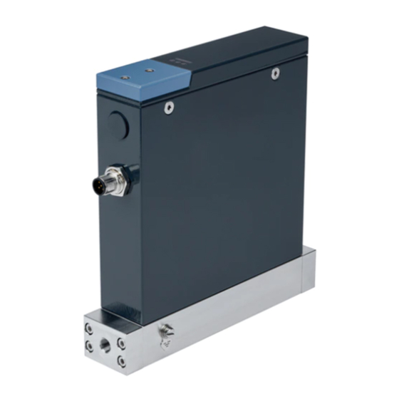
Page 10: Description
Type 8756 Description descripTiOn 3. Possible fluid connections: • G-threaded fluid connections according to DIN ISO228/1 Product variants • NPT-threaded fluid connections according to ASME/ ANSI B 1.20.1 5.1.1 Mass Flow Meter (MFM) • fluid connections with male vacuum-fittings • fluid connections with male compression-fittings 4. M4 screw for functional earth connection 5. Base block 6. Product status-indicator. The indicator operates according to Namur NE 107. 7. Status indicator of the connection to the Ethernet port 1 8. Status indicator of the fieldbus communication 9. Status indicator of the connection to the Ethernet port 2 10. M3 screw 11. Cover 12. büS-interface for Bürkert-Communicator software 13. Slot for the memory card Fig. -
Page 11: Mass Flow Controller (Mfc)
Type 8756 Description 5.1.2 Mass Flow Controller (MFC) 5. Base block 6. Pump 7. Product status-indicator. The indicator operates according to Namur NE 107. 8. Status indicator of the connection to the Ethernet port 1 9. Status indicator of the fieldbus communication 10. Status indicator of the connection to the Ethernet port 2 11. M3 screw 12. Cover 13. büS-interface for Bürkert-Communicator software 14. Slot for the memory card Fig. 2: Mass Flow Controller variants Pump of an MFC The pump is a micro-annular gear pump. NOTICE 1. Electrical connection, Analogue variant only: 5-pin M12 female connector, A coding The micro-annular gear pump is not completely tight. -
Page 12: Product Status-Indicator
Type 8756 Description Product status-indicator The product status indicator shows the product state. The colour of the product status indicator is based on the NAMUR NE 107 recom- mendation. Refer to Tab. 1. If different product states have been generated, the colour of the product status indicator shows the product state with the highest priority. Messages related to the product states are listed and possibly transmitted on any connected fieldbus. If the product status indicator flashes, then the product is selected in a man-machine interface such as the Bürkert Communicator software. Tab. 1: Product status indicator in accordance with NAMUR NE 107, edition 2006-06-12, active diagnostics colour of the product colour code product status meaning status indicator (for a plc) Green No event has been generated. →... -
Page 13: Memory Card
Type 8756 Description Memory card Bürkert-Communicator software NOTICE The MassFlowCommunicator is another PC software that is not compatible with the product. You cannot use the If the memory card is defective or lost, then buy a new memory PC software MassFlowCommunicator to configure or card from your Bürkert sales office. operate the product. The product is delivered with a memory card that is inserted in the product. The Type 8920 Bürkert-Communicator is a PC-software and At product start-up, there are two possibilities: enables the following actions, for example: • If product-specific data is stored on the inserted memory card, • Setting the parameters of the product, for example the basic the product adopts the data. At product delivery, the memory settings for the product start-up card contains product-specific data. To get a list of the stored • Running the diagnostics, and read the error memories for data, refer to the Help for the Initiation file that can be down- example loaded from country.burkert.com. -
Page 14: Büs /Canopen Variant
Type 8756 Description 5.5.1 büS /CANopen variant → Connect the jack male-connector of the AC/DC-adapter cable to the jack female-connector of the M12 female-con- To do the settings with the Type 8920 Bürkert-Communicator nector cable. software, do the following steps: → Connect the M12 female connector to the büS network. → Buy the USB-büS-interface set with article number 00772426 micro-USB from Bürkert. See Fig. 3. 5-pin M12 female connector connector jack AC/DC adapter female-connector büS stick with termina- tion-resistance switch Fig. 3: USB-büS-interface set with article number 00772426 → Download the latest version of the Type 8920 Bürkert-Com- municator software from country.burkert.com jack male-connector → During installation, the büS stick must not be inserted at the PC. Install the Bürkert-Communicator software on a PC. -
Page 15: Analogue Variant
Type 8756 Description → Wait until the Windows pilot of the büS stick has been com- pletely installed on the PC. → Connect the AC/DC adapter to the power supply. → Start the Bürkert-Communicator software. → Click on in the Bürkert-Communicator software to establish the communication between the Bürkert-Communi- Fig. 5: Assembled parts of the USB-büS-interface set with article cator software and the product. A window opens. number 00772551 → Select büs-stick. → Set the termination-resistance switch of the büS stick to ON. → Choose the port Bürkert büs stick, click on finish and wait → Insert the büS stick into a USB port of the PC. until the product symbol appears in the list of devices. → Energize the product. Refer to chpt. 8 Electrical installation. → In the list of devices, click on the symbol related to the product: the menu structure for the product is displayed. -
Page 16: Technical Data
Type 8756 Technical data Technical daTa Tab. 2: Operating conditions of the product Ambient temperature 0 °C...+50 °C Conformity Fluid temperature • MFM • –10 °C...+70 °C, only in liquid state The product complies with the EU directives according to the EU • MFC • –10 °C...+60 °C, only in liquid state declaration of conformity (if applicable). Ambient humidity < 95%, non-condensing Standards IP-Code according to Under the following conditions: EN 60529 The applied standards, which verify conformity with the EU direc- • Cables must be connected. tives, can be found on the EU type examination certificate and/or • Mating connectors must be plugged the EU declaration of conformity (if applicable). in and tightened. -
Page 17: Mechanical Data
Type 8756 Technical data Mechanical data Quality of the operating fluid • Liquids • Clean liquids Dimensions, weight: see data sheet of the product • Maximum particle size • 10 μm • Minimum dynamic viscosity • 0.3 mPa.s Tab. 3: Materials of the product • Maximum dynamic viscosity • 200 mPa.s Product part Material Take the pressure loss into Base-block Stainless steel 316L account. Refer to chpt. 6.5.2. Housing Painted aluminium, stainless steel Density measurement Sealing Refer to the Type label •... -
Page 18: Pressure Loss, Mfm
Type 8756 Technical data Mass flow rate measurement • Mass flow rate range • 0.1...25 kg/h • Measurement accuracy after • ±0.2% of the measured 1 minute warm-up time value PLUS ±0.0014 kg/h. 0.0014 kg/h = zero-point stability • Maximum measurement • 1:250 range The measurement range 7.5 10 12.5 15 17.5 20 22.5 is defined as the ratio of [kg/h] Qnominal of the product to Qmin. Qmin = 0.1 kg/h. Refer Nominal flow rate Q to Fig. 6. • Repeatability • ±0.1% of the measured Fig. 6: MFM: Measurement range depending on nominal flow rate value PLUS ±0.0007 kg/h... -
Page 19: Mass Flow Controller
Type 8756 Technical data Quality of the operating fluid ∆p [bar] • Liquids • Clean liquids • Maximum particle size • 10 μm • Minimum dynamic • 0.3 mPa.s viscosity • Maximum dynamic • 200 mPa.s, with reduced viscosity flow-rate range. If the flow rate is equal to 8 kg/h, then the fluid viscosity must be max. 50 mPa.s. Take the pressure loss into [kg/h] account. Refer to chpt. 6.5.4. Fig. 7: Pressure loss diagram, MFM, for water, in the measurement Density measurement range 0...25 kg/h... - Page 20 Type 8756 Technical data Mass flow rate measurement • Mass flow rate range • 0.1...8 kg/h • Control accuracy after • ±0.2% of the measured 1 minute warm-up time value PLUS ±0.0014 kg/h. If Qmin < 0.3kg/h, then the control accuracy can be higher. 0.0014 kg/h = zero-point [kg/h] stability • Maximum measurement • 1:80 Nominal flow rate Q range The measurement range is defined as the ratio of Qnominal Fig. 8: MFC: Measurement range depending on nominal flow rate of the product to Qmin.
-
Page 21: Pressure Loss, Mfc
Type 8756 Technical data Electrical data 6.5.4 Pressure loss, MFC A Mass Flow Controller (MFC) with pump has a pressure loss that 6.6.1 büS /CANopen variant depends on the operating fluid. WARNING Fig. 9. gives the pressure loss for water at 20 °C through an MFC with pump. ▶ For UL-certified components, only use limited power circuits p [bar] of "NEC Class 2". Tab. 7: Electrical data of an MFM Operating voltage 24 V DC ±10 % Maximum power 4 W consumption Communication büS and CANopen. The communication interface type can be chosen with the Bürk- ert-Communicator software. Pump inlet Pump outlet Tab. -
Page 22: Analogue Variant
Type 8756 Technical data 6.6.2 Analogue variant Tab. 10: Electrical data of an MFC Operating voltage 24 V DC ±10% WARNING residual ripple < 2 % Power consumption ▶ For UL-certified components, only use limited power circuits • Maximum power • 52 W of "NEC Class 2". consumption Tab. 9: Electrical data of an MFM • Typical power • 16 W for water and a flow rate of 8 kg/h consumption Operating voltage 24 V DC ±10 %... -
Page 23: Markings
Type 8756 Technical data Markings 6.7.2 Type label WARNING 8756 24V ... 4W [4W] Risk of injury that is due to escape of the fluid. IP65/IP67 NEC Class 2 only You can be injured through contact with the operating fluid, its 25.0 kg/h reaction products, and vapours. büS/CANopen You can be injured through inhalation of vapours. Ta= –10°C...+60°C S/N 1000 W41ME PS=100barg VAAg ▶... -
Page 24: Additional Markings
Type 8756 Installation insTallaTiOn 12. Ambient temperature 13. büS /CANopen variant: communication interface Safety instructions Analogue variant: input and output 14. Nominal mass flow rate (Q nominal) DANGER 15. IP-Code risk of injury that is due to pressure in the installation or in Fig. 11: Description of the Type label (example) the product. 6.7.3 Additional markings ▶... -
Page 25: Installation Steps
Type 8756 Installation Fluid installation WARNING The product has one of the following fluid connection types: risk of injury that is due to improper installation. • G1/8'' threaded fluid connections according to DIN ISO228/1 ▶ Only trained personnel can carry out the installation. Person- • NPT1/8'' threaded fluid connections according to ASME/ nel must use suitable tools. ANSI B 1.20.1 ▶ Secure the installation against unintentional actuation. • fluid connections with 1/4'' vaccum-fittings or 1/8'' ▶ Ensure a controlled restart after installation. vaccum-fittings Installation steps • fluid connections with 1/4'' double-ferrule fittings or 1/8'' dou- ble-ferrule fittings 1. Do the fluid installation into the pipe. Refer to chpt. 7.4 . • fluid connections with 6-mm double-ferrule fittings or 4-mm 2. Do the electrical installation. Refer to chpt. 8. - Page 26 Type 8756 Installation WARNING NOTICE malfunction that is due to the damage of the mfc pump. risk of injury that is due to leakage in an mfm. ▶ Mount a mesh filter upstream of the product. The mesh size ▶ At a low mass flow rate and a high pressure, make sure the must be of max. 10 µm. You can use the Type KF01 filter installation is tight. The tightness prevents incorrect meas- from Bürkert. urements or the leakage of the operating fluid. To make sure the installation is tight, observe the following Cavitation of gas in the liquid and degassing must be instructions: avoided. ▶ Use pipes with a diameter that is adapted to the fluid con- •...
-
Page 27: G1/8'' Threaded Fluid Connections
Type 8756 Installation 7.4.1 G1/8'' threaded fluid connections Flow direction → Remove the protective cap that closes the threaded connection. → Do the fluid connection on one side of the product. → Obey the instructions that are given by the manufacturer of the fitting used. → Obey the torques that are given by the manufacturer of the Risk of product mal- fitting used. function due to bubble → Do the fluid connection on the other side of the product in the collection same way. 7.4.2 NPT1/8'' threaded fluid connections → Do the fluid connection on one side of the product. → Obey the instructions that are given by the manufacturer of the fitting used. → Obey the torques that are given by the manufacturer of the Fig. 13: Horizontal mounting positions fitting used. -
Page 28: Fluid Connections With Double-Ferrule Fittings
Type 8756 Electrical installation elecTrical insTallaTiOn → Do the fluid connection on the other side of the product in the same way. Safety instructions 7.4.4 Fluid connections with double-ferrule fittings DANGER → Do the fluid connection on one side of the product. risk of injury from electric shocks. → Obey the instructions that are given by the manufacturer of ▶ Before working on the installation or the product, switch off the fitting used. the power. Ensure that nobody can reactivate the power. → Obey the torques that are given by the manufacturer of the ▶ Observe all applicable accident protection and all applicable fitting used. safety regulations for electrical equipment. → Do the fluid connection on the other side of the product in the WARNING same way. -
Page 29: Wiring The Büs /Canopen Variant
Type 8756 Electrical installation Wiring the büS /CANopen variant WARNING 8.2.1 With büS extension cables from Risk of injury from electromagnetic fields. Bürkert If the functional earth (FE) is not attached, then the requirements of the EMC directive are not met. NOTICE ▶ Connect the housing to the functional earth (FE). Use a green- requirements for the correct operation of the product. and-yellow cable that is as short as possible. And the cable cross-section must be at least equal to the cross section of ▶ Refer to the cabling guide that is available in English and the power-supply cable. German at country.burkert.com To wire the product, you can use büS extension cables from... -
Page 30: With Büs Cables From Bürkert
Type 8756 Electrical installation → Screw the mating female connector to the 5-pin male con- If you use a büS cable from Bürkert, then observe the signals of nector, to the torque given by the manufacturer of the mating the conductors as given in Tab. 13. female connector. Tab. 13: Signals of the büS cable conductors → Do the functional earthing of the product. Refer to chpt 8.4. Colour of the büS cable conductor Signal 8.2.2 With büS cables from Bürkert 24 V DC black DGND NOTICE white CAN_H requirements for the correct operation of the product. -
Page 31: With Canopen Cables
Type 8756 Electrical installation 8.2.3 With CANopen cables Pin Assignment Shield NOTICE 24 V requirements for the correct operation of the product. DGND ▶ Use shielded CANopen cables. The cable shielding can be CAN_H Coding lug either a braid shielding or a foil shielding. CAN_L M12 thread is internally connected to FE To wire the product, you can use mating female connectors from Bürkert. Refer to Tab. 14. Fig. 15: büS /CANopen MFM, büS /CANopen MFC:Pin assignment, 5-pin M12 male connector (A coding) Tab. -
Page 32: Wiring The Analogue Variant
Type 8756 Electrical installation Wiring the Analogue variant Pin Assignment Shield NOTICE 24 V requirements for the correct operation of the product. DGND ▶ Use shielded cables. The cable shielding can be either a Coding lug CAN_H braid shielding or a foil shielding. CAN_L requirements for the correct operation of the product. M12 thread is internally connected to FE • Use a mating female connector with shield-connection Fig. - Page 33 Type 8756 Electrical installation → Screw the mating female connector to the 5-pin male con- Pin Assignment nector, to the torque that is given by the manufacturer of the GND for the ana- mating female connector. logue output Coding lug → Wire the mating male connector according to the pin 24 V assignment of the M12 female connector in Fig. 19. Observe the instructions given by the manufacturer of the mating male Not connected connector. → Connect the cable shielding to the mating male connector. Measured value M12 thread is internally connected analogue output Pin Assignment to FE GND for the digital Fig. 17: Analogue MFM: Pin assignment, 5-pin M12 male connector (A input...
-
Page 34: Digital Input
Type 8756 Electrical installation 8.3.1 Digital input The 5-pin M12 female connector has a digital input. A digital input is used to remotely trigger a function. The following functions are available: • MFM or MFC: Reset the totalizer for the active fluid. • MFC: Start the function autotune. • MFC: Trigger the remote control of the pump or trigger the control of the pump by the product. Tab. 15 shows the function that is assigned by default to the digital input of the 5-pin M12 female connector of an MFM or an MFC. Tab. 15: Default assignment of the digital input of the 5-pin M12 female connector analogue variant default assignment reset totalizer start autotune → To choose the function to be remotely triggered over the digital input, use the Bürkert-Communicator software. Only one of the available functions can be associated to the digital input. -
Page 35: Relay Output
Type 8756 Electrical installation 8.3.2 Relay output → To choose the events that are assigned to the relay output, use the Bürkert-Communicator software. Several events can be The 5-pin M12 female connector has a relay output. The associated to the relay output. switching of the relay can show one of the following event: • MFM or MFC: A warning message has been generated. For Connecting the functional earth example if the supply voltage is too high, then a warning To do the functional earthing of the product, obey the following message is generated. instructions: • MFM or MFC: A failure message has been generated. For → Use a green-and-yellow cable that is as short as possible. example if a sensor failure is detected, then a failure message And the cable cross-section must be at least equal to the is generated. cross section of the power-supply cable. • MFC: The set-point value cannot be reached. → With a flat screwdriver of size 6.5 mm, loosen the M4 screw. -
Page 36: Start-Up
Type 8756 Start-up START-uP Start-up steps The operation of the product is tested at the factory with Safety instructions fluid. Residual fluid can remain in the fluidic parts of the product. DANGER To avoid personal injury: No zero adjustment is needed. ▶ Make sure the product operating-pressure is not higher than the operating pressure value on the product data-sheet. 1. Pressurise the pipes with operating fluid. Find the data sheet on our homepage: 2. Flush the pipes with operating fluid. country.burkert.com 3. Vent the pipes completely. WARNING 4. Energize the product. If product-specific data is stored on the inserted memory risk of injury from improper operation. card, then the product adopts the data. To get a list of the stored Improper operation can lead to injuries and damage to the data at product delivery, refer to the Help for the Initiation file that product and its environment. can be downloaded from country.burkert.com. ▶ Before start-up, make sure that the operating personnel are... -
Page 37: Operation
Type 8756 Operation OperaTiOn NOTICE When the pipes are empty and vented, the pump of an mfc 10.1 Safety instructions can be damaged if the pump runs dry. DANGER 6. If the product is an MFC, then run the function that is described in chpt. 10.2.5. This avoids damaging the pump. risk of injury that is due to pressure in the installation or in 7. If the product is an MFC, then run the Autotune function. -
Page 38: Functions
Type 8756 Operation 10.2 Functions DANGER 10.2.1 Empty-pipe detection Risk of injury that is due to escape of the fluid. You can be injured through contact with the operating fluid, its To detect if the pipe is empty, the product monitors the density reaction products, and vapours. value of the liquid. You can be injured through inhalation of vapours. If the density value is lower than 0.2 kg/l, then the pipe is empty. ▶ Observe all applicable accident protection and all applicable The product status-indicator is yellow. safety regulations relating to the operating fluid used. An out-of-specification event is generated. WARNING → If needed and if the product variant is an MFC, fill the pipe automatically as described in chpt. 10.2.5. risk of injury that is due to improper operation. -
Page 39: 10.2.3 Flush Bubbles From The Pipe
Type 8756 Operation 10.2.3 Flush bubbles from the pipe Go to sensor parameter advanced Limit on low cut off To make sure that there are no bubbles in the pipe, do the fol- 3. Set the cut-off limit in the range that is displayed. lowing procedure: The cut-off limit is set. → In the Bürkert-Communicator software, select the product. → Make sure that the product is filled with fluid. If you have an 10.2.5 Fill the pipe without damaging the MFC, use the function that controls the pipe filling. Refer to pump (MFC) chpt. 10.2.5. To make sure that the pump is not damaged when filling the → Go to actuator diagnostics... -
Page 40: Emergency Stop Of The Pump (Mfc)
Type 8756 Operation → Restart the product. If the operating mode of the fieldbus is büS, then the → Start the fucntion again. canopen status is set to Operational and the PDOs are sent to büS. 10.2.6 Emergency stop of the pump (MFC) If the operating mode of the fieldbus is CANopen, then the To avoid damage to the pump, the pump is automatically canopen status is set to pre-op until the CANopen network stopped when the following problems occur simultaneously: master switches the product to Operational. • The setpoint cannot be reached. 10.3.2 Increase the data transmission speed • The product has detected that the pipe is empty. If the data transmission-speed is increased, then the product The product status-indicator is red. provides more cyclic process-data. A error event is generated. For example, the actual value of the mass flow rate is available → Fill the pipe automatically as described in chpt. 10.2.5. -
Page 41: Operating Modes Of An Mfc
Type 8756 Operation 10.4 Operating modes of an MFC → If the bus load is less than or equal to 45%, then the data transmission-speed can be increased. Do the following: When energizing the product for the first time, the product enters a 1. In the Bürkert-Communicator software, select the product. short initialisation phase and then switches to the normal operating mode. The normal operating mode is described in chpt. 10.5. The product status-indicator flashes. The possible operating modes are described in Tab. 19. Go to general settings diagnostics inhibit time. Tab. 19: Names of the operating modes of an MFC in the Bürkert- To increase the data transmission-speed, click set dia- Communicator PC-software gnostic mode. The function inhibit time switches to set to... -
Page 42: Normal Operating Mode (Mfc)
Type 8756 Operation 10.5 Normal operating mode (MFC) The transmission means of the set-point value w and the measured value of the flow rate depends on the product. Refer to chpt. 10.5.1 The normal operating-mode is active when energizing the product büS/CANopen variant or to chpt. 10.5.2 Analogue variant. for the first time. Fig. 21 shows the normal operating-mode of an → To change the operating mode, change the source for the set- MFC. point values. Refer to chpt. 10.7. → If the operating conditions have changed, optimise the Electronics control parameters. Refer to chpt. 10.6. 10.5.1 büS/CANopen variant = w-x If the product detects that the pipe is empty, then the control function is impossible. → Fill the pipe as described in chpt. 10.2.5. After applying the operating voltage, the product enters a short Pump Sensor initialisation phase and then switches to the normal operating mode. -
Page 43: Optimise The Control Parameters (Mfc)
Type 8756 Operation • The measured value of the flow rate is transmitted over the WARNING analogue output according to the ranges in Tab. 20. Risk of injury from flowing fluid. Tab. 20: Analogue-input ranges and analogue-output ranges While the Autotune function is running, the mass flow can be Analogue Minimum value of the Maximum value of the higher than the nominal flow. output input ranges and output input ranges and output ▶ Before running the Autotune function, make sure no danger range ranges ranges can occur if the mass flow increases. 4...20 mA 4 mA, w = 0%... -
Page 44: Set-Point Values Without Communication (Büs/Canopen Mfc)
Type 8756 Operation If you change the source for the set-point value, then the operating point position (y) that is used. A restart of the product sets the mode of the MFC is changed. set-point position (y) to zero. • To change the source for the set-point value, change the setting analyze system: the product operates in the normal operating of the parameter set-point value source with the Bürkert-Com- mode but according to a predefined chronological sequence with municator PC-software. set-point values. Use the resulting diagram in combination with the graphical representation of process values to analyse the On a büS/CANopen variant you can alternatively change the related system with the Bürkert-Communicator software. object. Refer to the related procedure in the product-specific help in the documentation of the initiation files. Download the initiation 10.8 Set-point values without files and the related documentation at country.burkert.com. communication (büS/CANopen The setting of the parameter set-point value source is MFC) -
Page 45: Maintenance
Type 8756 Maintenance mainTenance DANGER If no heavily contaminated fluids are used and if the product is Risk of injury that is due to escape of the fluid. operated according to the Operating instructions, then the product You can be injured through contact with the operating fluid, its is maintenance-free. reaction products, and vapours. 11.1 Maintenance for operation with You can be injured through inhalation of vapours. heavily contaminated fluids ▶... -
Page 46: Replacing The Memory Card
Type 8756 Maintenance → Pay attention to the insertion direction of the memory card. WARNING Fig. 23 shows the final position of the memory card in the risk of injury that is due to improper maintenance. product. ▶ Only trained personnel can do the maintenance work. Per- sonnel must use suitable tools. ▶ Secure the installation against unintentional actuation. Inserted memory card ▶ Ensure a controlled restart after maintenance. 11.2 Replacing the memory card To replace the memory card on the product, do the following: Fig. 23: Cross-sectional drawing → De-energize the product. → With a TX8 screwdriver, screw the cover to a torque of 1.2 N·m, that is 0.9 lbf·ft. → With a TX8 screwdriver loosen the screws of the cover. -
Page 47: Troubleshooting If The Product Status-Indicator Shows A Problem
Type 8756 Maintenance 11.3 Troubleshooting if the product status-indicator shows a problem The product status indicator shows the product state. The colour of the product status indicator is based on the NAMUR NE 107 recom- mendation. If different product states have been generated, the colour of the product status indicator shows the product state with the highest priority. Messages related to the product states are listed and possibly transmitted on any connected fieldbus. 11.3.1 Troubleshooting if the product status-indicator is red Tab. 21: Troubleshooting, all product variants indicator according to description What to do? NE 107 Defective sensor. Defective memory. Maintenance is needed. Contact the manufacturer. Defective product. -
Page 48: Troubleshooting If The Product Status-Indicator Is Orange
Type 8756 Maintenance Tab. 23: Troubleshooting, specific to MFC variants indicator according to description What to do? NE 107 Incorrect Autotune. Autotune aborted. Make sure that the fluid flows through the product. Do the Autotune again. The pump has automatically stopped because the Fill the pipe automatically as described in chpt. 10.2.5. product has detected that the pipe is empty. 11.3.2 Troubleshooting if the product status-indicator is orange Tab. 24: Troubleshooting, specific to büS/CANopen variants indicator according to... -
Page 49: Troubleshooting If The Product Status-Indicator Is Yellow
Type 8756 Maintenance 11.3.3 Troubleshooting if the product status-indicator is yellow Tab. 26: Troubleshooting, all variants indicator according to description What to do? NE 107 Yellow One of the following values is out of specification: Operate the product within the specifications. • the fluid temperature • the product temperature • the supply voltage The sensor or the product can be damaged. The product has detected that the pipe is empty. • If the product variant is an MFC, then fill the pipe automatically as described in chpt. 10.2.5. • If the product variant is an MFM, then do the following steps: →... -
Page 50: Troubleshooting If The Product Status-Indicator Is Blue
Type 8756 Maintenance Tab. 27: Troubleshooting, specific to büS/CANopen variants indicator description What to do? according to NE 107 Yellow BüS /CANopen variant: Other fieldbus participants use the same Assign an individual node ID to each fieldbus participant. node ID. Tab. 28: Troubleshooting, specific to MFC variants indicator according to description What to do? NE 107 Yellow The set-point position for the pump has (almost) reached Decrease the back pressure. 100%. The set-point value cannot be reached. -
Page 51: Troubleshooting Of Other Problems
Type 8756 Maintenance 11.4 Troubleshooting of other problems 11.4.1 Product status-indicator is OFF, is flashing or goes out periodically Tab. 30: Troubleshooting if the product status-indicator is OFF, is flashing or goes out periodically problem possible cause What to do? The product status-in- The product is not energised. -
Page 52: No Mass Flow Rate
Type 8756 Maintenance 11.4.3 No mass flow rate Tab. 32: Troubleshooting if no mass flow rate, all product variants possible cause What to do? The pipes are too large or not yet fully vented. Vent the pipes. Change the pipe diameter. The flow-rate value is below the cut-off limit. If the cut-off limit is too high, decrease the value of the cut-off limit. Refer to 10.2.4. Tab. 33: Troubleshooting if no mass flow rate, specific to MFC product variants... -
Page 53: Set-Point Problems, Mfc Variants
Type 8756 Maintenance 11.4.5 Set-point problems, MFC variants problem possible cause What to do? Set-point value at 0 % There is pressure upstream the pump. The pressure makes Install the fluid container in such a way that no pressure is but operating fluid still the fluid flow. Pressure can be due to an incorrect position of generated upstream the pump. flows the fluid container. Set-point value at 0 %, The installation position of the product is incorrect. Install the product as recommended in chpt. 7.4. And run the no mass flow, but a Autotune function to adapt to the operating conditions. non-zero mass flow There are bubbles in the sensor. The relay output of an Ana- Flush the product fluidic parts to remove the bubbles. Do the rate is measured logue device variant can be parametered to switch when procedure that is described in chpt. 10.2.3. there are bubbles in the sensor. Set-point value is not The mesh filter is clogged. Clean or replace the mesh filter. reached The outlet pressure is too high. Make sure that the pipe diameters and the pipe lengths are adapted. -
Page 54: Accessories /Spare Parts
Type 8756 Accessories /Spare Parts ACCESSORIES /SPARE PARTS Tab. 36: Electrical accessories, Analogue variant item article number CAUTION USB-büS-interface set, without power 772551 supply risk of injury and risk of material damage that are due to Memory card On request unsuitable parts. → For further accessories, refer to the product data sheet. Incorrect accessories and unsuitable replacement parts can cause injuries and damage to the product and its environment. -
Page 55: Decommissioning
Type 8756 Decommissioning decOmmissiOning DANGER 13.1 Safety instructions Risk of injury from dangerous fluids. You can be injured through contact with the operating fluid, its DANGER reaction products, and vapours. You can be injured through inhalation of vapours. risk of injury that is due to pressure in the installation and in ▶ Before you disconnect pipes or valves, flush out dangerous the product. fluids, release pressure in the pipes and drain. ▶ Before working on the installation or product, cut the pres- ▶ Observe all applicable accident protection and all applicable sure. Vent and drain the pipes. -
Page 56: Transport
Type 8756 Transport TranspOrT NOTICE Transport damage. Fluid If the product is not protected in transport, the product can be connections damaged. Fig. 24: Fluid connections, for example threaded connections • Remove cables, connectors, product-external filters and installation → Remove the product. equipment. • Protect the electrical interfaces with protective plugs. • Clean and vent contaminated products. • Close the fluid connections with protective caps. Protective caps ensure protection and sealing. • Pack the product in two suitable zip lock bags, to avoid any contamination during the transport. -
Page 57: Storage, Disposal
Type 8756 Storage, disposal STORAGE, DISPOSAl NOTICE incorrect storage can cause damage to the product. • Close fluid connections with protective caps. • Store the product dry and dust-free in sealed zip lock bags. • Storage temperature: –10...+70 °C. environmental damage that is due to parts contaminated by fluids. • Dispose of the product and its packaging in an environmen- tally friendly manner. • Comply with applicable environmental and disposal regulations. reTurning The prOducT no work or tests will be carried out on the product until a valid contamination declaration has been received. - Page 58 Type 8756 English...
- Page 60 www.burkert.com...
Need help?
Do you have a question about the 8756 and is the answer not in the manual?
Questions and answers