National Instruments NI cDAQ-9139 User Manual
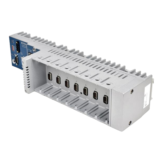
Eight-slot controller
Hide thumbs
Also See for NI cDAQ-9139:
- Safety, environmental, and regulatory information (4 pages) ,
- User manual (139 pages) ,
- Quick start manual (6 pages)

Related Manuals for National Instruments NI cDAQ-9139


Summary of Contents for National Instruments NI cDAQ-9139
- Page 1 (217) 352-9330 | Click HERE Find the National Instruments cDAQ-9133 at our website:...
- Page 2 NI cDAQ -9138/9139 User Manual NI CompactDAQ Eight-Slot Controller NI cDAQ-9138/9139 User Manual March 2016 371042D-01...
- Page 3 11500 North Mopac Expressway Austin, Texas 78759-3504 USA Tel: 512 683 0100 For further support information, refer to the appendix. To comment on NI NI Services documentation, refer to the NI website at and enter the Info Code ni.com/info feedback © 2012–2016 National Instruments. All rights reserved.
- Page 4 National Instruments Corporation. National Instruments respects the intellectual property of others, and we ask our users to do the same. NI software is protected by copyright and other intellectual property laws. Where NI software may be used to reproduce software or other materials belonging to others, you may use NI software only to reproduce materials that you may reproduce in accordance with the terms of any applicable license or other legal restriction.
- Page 5 ™ The ExpressCard word mark and logos are owned by PCMCIA and any use of such marks by National Instruments is under license. The mark LabWindows is used under a license from Microsoft Corporation. Windows is a registered trademark of Microsoft Corporation in the United States and other countries.
-
Page 6: Table Of Contents
CFast SSD Module ....................1-34 Cables and Accessories ....................1-34 Using the cDAQ Controller ....................1-35 C Series Module ....................... 1-35 Parallel versus Serial DIO Modules ..............1-36 cDAQ Module Interface ................... 1-36 STC3......................... 1-36 Processor and Ports....................1-37 © National Instruments | v... - Page 7 Contents Chapter 2 Analog Input Analog Input Triggering Signals ..................2-1 Analog Input Timing Signals.................... 2-1 AI Sample Clock Signal ...................2-2 Routing the Sample Clock to an Output Terminal ........... 2-2 AI Sample Clock Timebase Signal ................2-2 AI Convert Clock Signal Behavior For Analog Input Modules ....... 2-2 Scanned Modules....................
- Page 8 Sample Clocked Buffered Pulse Measurement ..........5-8 Semi-Period Measurement ..................5-8 Single Semi-Period Measurement ..............5-9 Implicit Buffered Semi-Period Measurement........... 5-9 Pulse versus Semi-Period Measurements ............5-10 Frequency Measurement................... 5-10 Low Frequency with One Counter ..............5-11 © National Instruments | vii...
- Page 9 Contents High Frequency with Two Counters..............5-12 Large Range of Frequencies with Two Counters ..........5-13 Sample Clocked Buffered Frequency Measurement ........5-14 Choosing a Method for Measuring Frequency ..........5-15 Which Method Is Best?..................5-16 Period Measurement ....................5-18 Position Measurement....................
- Page 10 Clock Routing........................6-1 80 MHz Timebase ....................6-2 20 MHz Timebase ....................6-2 100 kHz Timebase ....................6-2 Appendix A Controller Operating System and Configuration Appendix B Where to Go from Here Appendix C NI Services Index © National Instruments | ix...
-
Page 11: Getting Started With The Cdaq Controller
The National Instruments CompactDAQ cDAQ-9138 controller features the 1.06 GHz Celeron processor. The National Instruments CompactDAQ cDAQ-9139 controller features the 1.33 GHz Intel Core i7 processor. The NI cDAQ-9138 and NI cDAQ-9139 are available as a Windows Embedded Standard 7 (WES7) or a LabVIEW Real-Time system. -
Page 12: Safety Guidelines
Product misuse can result in a hazard. You can compromise the safety protection built into the product if the product is damaged in any way. If the product is damaged, return it to National Instruments for repair. Because some C Series modules may have more stringent certification... -
Page 13: Electromagnetic Compatibility Guidelines
Furthermore, any modifications to the product not expressly approved by National Instruments could void your authority to operate it under your local regulatory rules. -
Page 14: Unpacking
At the end of the product life cycle, all products must be sent to EU Customers a WEEE recycling center. For more information about WEEE recycling centers, National Instruments WEEE initiatives, and compliance with WEEE Directive 2002/96/EC on Waste and Electronic Equipment, visit ni.com/environment/... -
Page 15: Installing The Ni Cdaq-9138/9139 For Windows
The NI-DAQmx driver software preloaded onto your cDAQ controller is available for download . The documentation for NI-DAQmx is available from Start»All ni.com/support Programs»National Instruments»NI-DAQ. Other NI documentation is available from ni.com/manuals Refer to Figure 1-1 while completing the following assembly steps. - Page 16 Chapter 1 Getting Started with the cDAQ Controller Connect a computer keyboard and mouse to the bottom two USB ports on the cDAQ controller. Attach a ring lug to a 1.31 mm (16 AWG) or larger wire. Remove the ground screw from the ground terminal on the front panel.
- Page 17 When in use, the cDAQ controller may become warm to the touch. This is Note normal. The network behavior is determined by the Windows network drivers. Refer Note to the Windows documentation for information about configuring IP settings. © National Instruments | 1-7...
-
Page 18: Installing The Ni Cdaq-9138/9139 For Labview Real-Time
Chapter 1 Getting Started with the cDAQ Controller You can use the cDAQ controller BIOS setup utility to configure the cDAQ Note controller to start immediately when power is applied or to respond to the front-panel power button. Refer to the section of Power/Wake Configuration Submenu Appendix A,... - Page 19 The NI-DAQmx driver software is included on the disk shipped with your kit and is available for download at . The documentation for NI-DAQmx is available after ni.com/support installation from Start»All Programs»National Instruments»NI-DAQ. Other NI documentation is available from ni.com/manuals Power on the host computer and connect it to an Ethernet network.
- Page 20 Chapter 1 Getting Started with the cDAQ Controller Verify that the DISABLE RT DIP switch is in the OFF position so that the controller will boot into LabVIEW Real-Time. Refer to the section for more information DIP Switches about the DISABLE RT DIP switch. Figure 1-4.
- Page 21 For information about configuring network settings, refer to the Configure Note Network Settings book of the MAX Remote Systems Help. In MAX, click Help»Help The serial number listed in MAX is the last eight digits of the cDAQ controller primary MAC address. © National Instruments | 1-11...
-
Page 22: Troubleshooting Network Communication In Ni Cdaq-9138/9139 For Labview Real-Time Controller
Chapter 1 Getting Started with the cDAQ Controller Topics»Remote Systems. On the Contents tab, browse to LabVIEW Real-Time Target Configuration»Configure Network Settings. For information about configuring the controller to launch an embedded stand-alone application at startup, refer to the LabVIEW Help. For more information about setting up the controller as an RT target, refer to the LabVIEW Help. - Page 23 Optionally, you can connect the positive lead of a secondary power source to the V2 terminal and the negative lead to the other C terminal. © National Instruments | 1-13...
-
Page 24: Mounting The Cdaq Controller
Chapter 1 Getting Started with the cDAQ Controller Install the power connector plug on the front panel of the cDAQ controller and tighten the connector screw flanges. Turn on the external power source(s). The cDAQ controller uses V1 if the voltage across V1 and C is 9 V or greater. If the V1-to-C voltage drops below 9 V, the cDAQ controller switches to V2. - Page 25 50.8 mm (2.00 in.) 50.8 mm 29.2 mm (2.00 in.) (1.15 in.) Measure Ambient Measure Ambient Temperature Here Temperature Here 50.8 mm 50.8 mm (2.00 in.) 63.5 mm 63.5 mm (2.00 in.) (2.50 in.) (2.50 in.) © National Instruments | 1-15...
-
Page 26: Using The Cdaq Controller On A Desktop
Chapter 1 Getting Started with the cDAQ Controller Your installation must meet the following requirements for space and Caution cabling clearance, as shown in Figure 1-10: • Allow 50.8 mm (2 in.) on the top and the bottom of the controller for air circulation. -
Page 27: Mounting The Cdaq Controller On A Panel
Fasten the mounting plate to the controller using a number 2 Phillips screwdriver and six M4 × 10 screws. National Instruments provides these screws with the panel mount kit. Tighten the screws to a maximum torque of 1.3 N · m (11.5 lb · in.). - Page 28 (0.88 in.) (0.38 in.) 7.2 mm 193.7 mm 193.7 mm 2.5 mm (0.29 in.) (7.63 in.) (7.63 in.) (0.10 in.) NI cDAQ-9139 cDAQ-9139 NI CompactDAQ NI CompactDAQ 114.3 mm (4.50 in.) 25.4 mm (1.00 in.) 108.9 mm 188.6 mm 108.9 mm (4.29 in.)
-
Page 29: Mounting The Cdaq Controller On A Din Rail
Fasten the DIN rail clip to the controller using a number 2 Phillips screwdriver and three M4 × 10 screws. National Instruments provides these screws with the DIN rail mount kit. Tighten the screws to a maximum torque of 1.3 N · m (11.5 lb · in.). Make sure the DIN rail kit is installed as shown in Figure 1-16, with the larger lip of the DIN clip positioned up. -
Page 30: Mounting The Cdaq Controller On A Rack
Chapter 1 Getting Started with the cDAQ Controller Figure 1-16. Installing the DIN Rail Clip on the cDAQ Controller Insert one edge of the DIN rail into the deeper opening of the DIN rail clip, as shown in Figure 1-17, and press down firmly on the controller to compress the spring until the clip locks in place on the DIN rail. -
Page 31: Removing Modules From The Cdaq Controller
BLUE RETURN Ground reference 5 V power for DDC Ground return for power No Connect — DDC_D Data signal of serial communication HSYNC Horizontal synchronization signal VSYNC Vertical synchronization signal DDC_C Clock signal of serial communication © National Instruments | 1-21... -
Page 32: Usb Ports
Chapter 1 Getting Started with the cDAQ Controller Do not hot-swap VGA devices while the cDAQ controller is in a Caution hazardous location or connected to high voltages. USB Ports The cDAQ controller supports common USB mass-storage devices such as USB Flash drives and USB-to-IDE adapters formatted with FAT16 and FAT32 file systems. -
Page 33: Ethernet Leds
Ethernet ACT/LINK and 10/100/1000 LAN connector LEDs. Table 1-5. Ethernet LED Indications LED Color LED State Indication ACT/ — LAN link not established LINK Green Solid LAN link established Flashing Activity on LAN © National Instruments | 1-23... -
Page 34: Ethernet Cabling
Chapter 1 Getting Started with the cDAQ Controller Table 1-5. Ethernet LED Indications (Continued) LED Color LED State Indication 10/100/ Yellow Solid 1,000 Mbit/s data rate selected 1000 Green Solid 100 Mbit/s data rate selected — 10 Mbit/s data rate selected Ethernet Cabling Table 1-6 shows the shielded Ethernet cable wiring connections for both straight through and crossover cables. -
Page 35: Rs-232 Serial Port
COM 2 is designed to operate in four-wire (RS-422) or two-wire mode. NI offers a DIN rail-mountable screw terminal adapter (NI part number 778674-01) that you can use to connect termination resistors to COM 2. © National Instruments | 1-25... -
Page 36: Mxi-Express Port
Chapter 1 Getting Started with the cDAQ Controller Cable adapters for the 10-position modular jacks are available from NI. Part numbers 182845-01, -02, and -03 are 1, 2, and 3 m cable adapters for connecting the 10-position modular jack to a 9-position D-SUB plug. Go to and enter Info Code for up-to-date information about supported... - Page 37 Keep the SAFE MODE switch in the OFF position during normal operation. NI recommends that you keep the (NI cDAQ-9138/9139 for Windows) SAFE MODE switch in the OFF position at all times. © National Instruments | 1-27...
- Page 38 Chapter 1 Getting Started with the cDAQ Controller Table 1-7. DIP Switches (Continued) Switch Description CONSOLE OUT The position of the (NI cDAQ-9138/9139 for LabVIEW Real-Time) CONSOLE OUT switch determines whether console input and output are redirected to the RS-232 serial port. If the switch is in the ON position, console input and output are redirected to the RS-232 serial port.
-
Page 39: Power Connector
4 seconds. Refer to the section of Appendix A, Power/Wake Configuration Submenu Configuration, for information about configuring how the Controller Operating System and controller responds to the power button. © National Instruments | 1-29... -
Page 40: Leds
Chapter 1 Getting Started with the cDAQ Controller LEDs The cDAQ controller features four LEDs—POWER, DRIVE, STATUS, and USER1—on its front panel, two LEDs—ACT/LINK and 10/100/1000—near each Ethernet connector, and one LINK LED near the MXI-Express port. Refer to Figure 1-1 for the locations of the LEDs. Table 1-8 lists the LEDs and status indications. - Page 41 Continuously Software error—The controller has detected an flashing unrecoverable error. Contact National Instruments. Continuously Software error—The device may be configured for DHCP flashing or but unable to get an IP address because of a problem with solid the DHCP server.
-
Page 42: Cmos Battery And Cmos Reset Button
Ensure that the ambient operating temperature does not exceed the range specified in the Environmental section of the specifications document for your cDAQ controller. If the problem persists, contact National Instruments. — Normal operation. USER1 Green/ —... -
Page 43: Chassis Grounding Screw
(5 ft). Attach the wire to the earth ground of the facility’s power system. For more information about earth ground connections, refer to the KnowledgeBase document, Grounding for Test and Measurement Devices, by going to and entering the Info Code ni.com/info emcground © National Instruments | 1-33... -
Page 44: Cpu Expansion Module (Cxm) Connector
Chapter 1 Getting Started with the cDAQ Controller If you use shielded cabling to connect to a C Series module with a plastic Note connector, you must attach the cable shield to the chassis grounding terminal using 1.31 mm (16 AWG) or larger wire. Use shorter wire for better EMC performance. CPU eXpansion Module (CXM) Connector In the future, the CXM connector will enable you to connect additional industry-standard I/O to the cDAQ controller. -
Page 45: Using The Cdaq Controller
MXI Express C Series Module National Instruments C Series modules provide built-in signal conditioning and screw terminal, spring terminal, BNC, D-SUB, or RJ-50 connectors. A wide variety of I/O types are available, allowing you to customize the cDAQ controller to meet your application needs. -
Page 46: Parallel Versus Serial Dio Modules
Chapter 1 Getting Started with the cDAQ Controller modules to your sensors/actuators. C Series modules can sometimes provide isolation from channel-to-earth ground and channel-to-channel. For more information about which C Series modules are compatible with the cDAQ controller, refer to the C Series Support in NI-DAQmx document by going to and entering ni.com/info the Info Code... -
Page 47: Processor And Ports
Refer to the specifications document for your cDAQ controller for information about the processors on the cDAQ controller. Refer to the section for cDAQ Controller Features information about using the various ports on the cDAQ controller. © National Instruments | 1-37... -
Page 48: Analog Input
Analog Input Timing Signals The cDAQ controller features the following analog input timing signals: • AI Sample Clock Signal* • AI Sample Clock Timebase Signal • AI Start Trigger Signal* © National Instruments | 2-1... -
Page 49: Ai Sample Clock Signal
AI Convert Clock Signal Behavior For Analog Input Modules Refer to the Scanned Modules, Simultaneous Sample-and-Hold Modules, Sigma-Delta Modules, sections for information about the AI Convert Clock signal and Slow Sample Rate Modules C Series analog input modules. © National Instruments | 2-2... -
Page 50: Scanned Modules
Chapter 2 Analog Input Scanned Modules Scanned C Series analog input modules contain a single A/D converter and a multiplexer to select between multiple input channels. When the cDAQ Module Interface receives a Sample Clock pulse, it begins generating a Convert Clock for each scanned module in the current task. Each Convert Clock signals the acquisition of a single channel from that module. -
Page 51: Slow Sample Rate Modules
Once the acquisition begins, configure the acquisition to stop in one of the following ways: • When a certain number of points has been sampled (in finite mode) • After a hardware reference trigger (in finite mode) • With a software command (in continuous mode) © National Instruments | 2-4... -
Page 52: Using A Digital Source
Chapter 2 Analog Input An acquisition that uses a start trigger (but not a reference trigger) is sometimes referred to as a posttriggered acquisition. That is, samples are measured only after the trigger. When you are using an internal sample clock, you can specify a default delay from the start trigger to the first sample. -
Page 53: Using A Digital Source
Depending on the C Series module capabilities, you may need two modules Note to utilize analog triggering. Routing the Reference Trigger Signal to an Output Terminal You can route Reference Trigger to any output PFI terminal. Reference Trigger is active high by default. © National Instruments | 2-6... -
Page 54: Ai Pause Trigger Signal
Chapter 2 Analog Input AI Pause Trigger Signal You can use the Pause Trigger to pause and resume a measurement acquisition. The internal sample clock pauses while the external trigger signal is active and resumes when the signal is inactive. You can program the active level of the pause trigger to be high or low. Using a Digital Source To use the Pause Trigger, specify a source and a polarity. -
Page 55: Analog Output
You can configure software-timed generations to simultaneously update • Only one simultaneous update task can run at a time • A hardware-timed AO task and a simultaneous update AO task cannot run at the same time © National Instruments | 3-1... -
Page 56: Hardware-Timed Generations
Chapter 3 Analog Output Hardware-Timed Generations With a hardware-timed generation, a digital hardware signal controls the rate of the generation. This signal can be generated internally on the controller or provided externally. Hardware-timed generations have several advantages over software-timed acquisitions: •... -
Page 57: Analog Output Triggering Signals
Figure 3-1. Analog Output Timing Options Analog Comparison Event AO Sample Clock Ctr n Internal Output Analog Comparison AO Sample Clock Event Timebase Programmable 20 MHz Timebase Clock Divider 80 MHz Timebase 100 kHz Timebase © National Instruments | 3-3... -
Page 58: Routing Ao Sample Clock To An Output Terminal
Chapter 3 Analog Output Routing AO Sample Clock to an Output Terminal You can route AO Sample Clock to any output PFI terminal. AO Sample Clock is active high by default. AO Sample Clock Timebase Signal The AO Sample Clock Timebase (ao/SampleClockTimebase) signal is divided down to provide a source for AO Sample Clock. -
Page 59: Routing Ao Start Trigger Signal To An Output Terminal
Help for more information. Using an Analog Source Some C Series modules can generate a trigger based on an analog signal. In NI-DAQmx, this is called the Analog Comparison Event, depending on the trigger properties. © National Instruments | 3-5... -
Page 60: Minimizing Glitches On The Output Signal
Chapter 3 Analog Output When you use an analog trigger source, the samples are paused when the Analog Comparison Event signal is at a high or low level, depending on the trigger properties. The analog trigger circuit must be configured by a simultaneously running analog input task. Depending on the C Series module capabilities, you may need two modules Note to utilize analog triggering. -
Page 61: Digital Input/Output And Pfi
You can only do hardware timing in one direction at a time on a serial bidirectional module. To determine the capability of digital I/O modules supported by the cDAQ controller, refer to the C Series Support in NI-DAQmx document by going to and entering the Info ni.com/info Code rdcdaq © National Instruments | 4-1... -
Page 62: Static Dio
Chapter 4 Digital Input/Output and PFI Static DIO Each of the DIO lines can be used as a static DI or DO line. You can use static DIO lines to monitor or control digital signals on some C Series modules. Each DIO line can be individually configured as a digital input (DI) or digital output (DO), if the C Series module being used allows such configuration. - Page 63 • DI Change Detection Output Several other internal signals can be routed to DI Sample Clock. Refer to the Device Routing in MAX topic in the NI-DAQmx Help or the LabVIEW Help for more information. © National Instruments | 4-3...
- Page 64 Chapter 4 Digital Input/Output and PFI Using an External Source You can route the following signals as DI Sample Clock: • Any PFI terminal • Analog Comparison Event (an analog trigger) You can sample data on the rising or falling edge of DI Sample Clock. Routing DI Sample Clock to an Output Terminal You can route DI Sample Clock to any output PFI terminal.
- Page 65 Refer to the Device Routing in MAX topic in the NI-DAQmx Help or the LabVIEW Help for more information. Using an Analog Source Some C Series modules can generate a trigger based on an analog signal. In NI-DAQmx, this is called the Analog Comparison Event. © National Instruments | 4-5...
-
Page 66: Digital Input Filters
Chapter 4 Digital Input/Output and PFI When you use an analog trigger source, the acquisition stops on the first rising or falling edge of the Analog Comparison Event signal, depending on the trigger properties. Depending on the C Series module capabilities, you may need two modules Note to utilize analog triggering. -
Page 67: Getting Started With Di Applications In Software
The rising and falling edge lines do not necessarily have to be in the task. Tp is a nominal value; the accuracy of the controller timebase and I/O distortion will affect this value. © National Instruments | 4-7... -
Page 68: Digital Output
Chapter 4 Digital Input/Output and PFI Change detection acquisitions can be buffered or nonbuffered: • Nonbuffered Change Detection Acquisition—In a nonbuffered acquisition, data is transferred from the cDAQ controller directly to a PC buffer. • Buffered Change Detection Acquisition—A buffer is a temporary storage in computer memory for acquired samples. -
Page 69: Digital Output Triggering Signals
If the program does not write new data to the buffer at a fast enough rate to keep up with the generation, the buffer underflows and causes an error. Digital Output Triggering Signals Digital output supports two different triggering actions: DO Start Trigger and DO Pause Trigger. © National Instruments | 4-9... -
Page 70: Digital Output Timing Signals
Chapter 4 Digital Input/Output and PFI A digital or analog trigger can initiate these actions. Any PFI terminal can supply a digital trigger, and some C Series analog modules can supply an analog trigger. For more information, refer to the documentation included with your C Series module(s). Refer to the sections for more DO Start Trigger Signal... - Page 71 When you generate digital output signals, the generation pauses as soon as the pause trigger is asserted. If the source of the sample clock is the onboard clock, the generation resumes as soon as the pause trigger is deasserted, as shown in Figure 4-5. © National Instruments | 4-11...
- Page 72 Chapter 4 Digital Input/Output and PFI Figure 4-5. DO Pause Trigger with the Onboard Clock Source Pause Trigger Sample Clock If you are using any signal other than the onboard clock as the source of the sample clock, the generation resumes as soon as the pause trigger is deasserted and another edge of the sample clock is received, as shown in Figure 4-6.
-
Page 73: Getting Started With Do Applications In Software
Assume that an input terminal has been low for a long time. The input terminal then changes from low to high, but glitches several times. When the Filter Clock has sampled the signal high © National Instruments | 4-13... - Page 74 Chapter 4 Digital Input/Output and PFI on N consecutive edges, the low-to-high transition is propagated to the rest of the circuit. The value of N depends on the filter setting, as shown in Table 4-1. Table 4-1. Selectable PFI Filter Settings Min Pulse Filter Width...
-
Page 75: Counters
(Embedded Ctrn) for use in what are traditionally two-counter measurements and generations. The embedded counters cannot be programmed independent of the main counter; signals from the embedded counters are not routable. © National Instruments | 5-1... -
Page 76: Counter Timing Engine
Chapter 5 Counters Counter Timing Engine Unlike analog input, analog output, digital input, and digital output, the cDAQ controller counters do not have the ability to divide down a timebase to produce an internal counter sample clock. For sample clocked operations, an external signal must be provided to supply a clock source. -
Page 77: Counter Input Applications
Source input after the counter is armed. On-demand refers to the fact that software can read the counter contents at any time without disturbing the counting process. Figure 5-2 shows an example of single point edge counting. Figure 5-2. Single Point (On-Demand) Edge Counting Counter Armed SOURCE Counter Value © National Instruments | 5-3... -
Page 78: Buffered (Sample Clock) Edge Counting
Chapter 5 Counters You also can use a pause trigger to pause (or gate) the counter. When the pause trigger is active, the counter ignores edges on its Source input. When the pause trigger is inactive, the counter counts edges normally. You can route the pause trigger to the Gate input of the counter. -
Page 79: Pulse-Width Measurement
FIFO and ignores other edges on the Gate and Source inputs. Software then reads the stored count. Figure 5-5 shows an example of a single pulse-width measurement. Figure 5-5. Single Pulse-Width Measurement GATE SOURCE Counter Value Latched Value © National Instruments | 5-5... -
Page 80: Implicit Buffered Pulse-Width Measurement
Chapter 5 Counters Implicit Buffered Pulse-Width Measurement An implicit buffered pulse-width measurement is similar to single pulse-width measurement, but buffered pulse-width measurement takes measurements over multiple pulses. The counter counts the number of edges on the Source input while the Gate input remains active. On each trailing edge of the Gate signal, the counter stores the count in the counter FIFO. -
Page 81: Pulse Measurement
The counter begins counting when it is armed. The arm usually occurs between edges on the Gate input but the counting does not start until the desired edge. You can select whether to read the high pulse or low pulse first using the StartingEdge property in NI-DAQmx. © National Instruments | 5-7... -
Page 82: Sample Clocked Buffered Pulse Measurement
Chapter 5 Counters Figure 5-9 shows an example of an implicit buffered pulse measurement. Figure 5-9. Implicit Buffered Pulse Measurement Counter Armed Gate Source Buffer Sample Clocked Buffered Pulse Measurement A sample clocked buffered pulse measurement is similar to single pulse measurement, but a buffered pulse measurement takes measurements over multiple pulses correlated to a sample clock. -
Page 83: Single Semi-Period Measurement
Figure 5-11 shows an example of an implicit buffered semi-period measurement. Figure 5-11. Implicit Buffered Semi-Period Measurement Counter Starting Armed Edge GATE SOURCE Counter Value Buffer For information about connecting counter signals, refer to the Default Counter/Timer Routing section. © National Instruments | 5-9... -
Page 84: Pulse Versus Semi-Period Measurements
Chapter 5 Counters Pulse versus Semi-Period Measurements In hardware, pulse measurement and semi-period are the same measurement. Both measure the high and low times of a pulse. The functional difference between the two measurements is how the data is returned. In a semi-period measurement, each high or low time is considered one point of data and returned in units of seconds or ticks. -
Page 85: Low Frequency With One Counter
You can configure the counter to measure one period of the gate signal. The frequency of fx is the inverse of the period. Figure 5-12 illustrates this method. Figure 5-12. Low Frequency with One Counter Interval Measured Gate … … Source Single Period Period of fx = Measurement Frequency of fx = © National Instruments | 5-11... -
Page 86: High Frequency With Two Counters
Chapter 5 Counters High Frequency with Two Counters For high frequency measurements with two counters, you measure one pulse of a known width using your signal and derive the frequency of your signal from the result. Counter 0 is always paired with Counter 1. Counter 2 is always paired with Note Counter 3. - Page 87 From Counter 0, the length of the pulse is N/fx. From Counter 1, the length of the same pulse is J/fk. Therefore, the frequency of fx is given by fx = fk * (N/J). © National Instruments | 5-13...
- Page 88 Chapter 5 Counters Sample Clocked Buffered Frequency Measurement Sample clocked buffered point frequency measurements can either be a single frequency measurement or an average between sample clocks. Use CI.Freq.EnableAveraging to set the behavior. For buffered frequency, the default is True. A sample clocked buffered frequency measurement with CI.Freq.EnableAveraging set to True uses the embedded counter and a sample clock to perform a frequency measurement.
-
Page 89: Choosing A Method For Measuring Frequency
N/fx where N is the divide down. • Sample clocked—For sample clocked frequency measurements, a known timebase is counted for the source frequency (fk). The measurement time is the period of the sample clock (fs). © National Instruments | 5-15... -
Page 90: Which Method Is Best
Chapter 5 Counters Table 5-2. Frequency Measurement Methods Two Counter High Variable Sample Clocked One Counter Frequency Large Range Known timebase Known Known timebase timebase ------------------------------- gating period gating period Measurement time --- - --- - --- - Max. ------------------------------ - ... - Page 91 50 k and 5 M with a measurement time of 1 ms the error percentage is still close to 0.00125%. One of the disadvantages of a sample clocked frequency measurement is that the frequency to be measured © National Instruments | 5-17...
-
Page 92: Period Measurement
Chapter 5 Counters must be at least twice the sample clock rate to ensure that a full period of the frequency to be measured occurs between sample clocks. • Low frequency measurements with one counter is a good method for many applications. However, the accuracy of the measurement decreases as the frequency increases. -
Page 93: Position Measurement
X2 Encoding—The same behavior holds for X2 encoding except the counter increments or decrements on each edge of channel A, depending on which channel leads the other. Each cycle results in two increments or decrements, as shown in Figure 5-18. © National Instruments | 5-19... -
Page 94: Channel Z Behavior
Chapter 5 Counters Figure 5-18. X2 Encoding Ch A Ch B Counter Value 5 • X4 Encoding—Similarly, the counter increments or decrements on each edge of channels A and B for X4 encoding. Whether the counter increments or decrements depends on which channel leads the other. -
Page 95: Measurements Using Two Pulse Encoders
Gate input of the counter. You can configure the counter to sample on the rising or falling edge of the sample clock. Figure 5-22 shows an example of a buffered X1 position measurement. © National Instruments | 5-21... -
Page 96: Two-Signal Edge-Separation Measurement
Chapter 5 Counters Figure 5-22. Buffered Position Measurement Counter Armed Sample Clock (Sample on Rising Edge) Ch A Ch B Count Buffer Two-Signal Edge-Separation Measurement Two-signal edge-separation measurement is similar to pulse-width measurement, except that there are two measurement signals—Aux and Gate. An active edge on the Aux input starts the counting and an active edge on the Gate input stops the counting. -
Page 97: Implicit Buffered Two-Signal Edge-Separation Measurement
On the next active edge of the Gate signal, the counter begins another measurement. The STC3 transfers the sampled values to host memory using a high-speed data stream. Figure 5-25 shows an example of a sample clocked buffered two-signal separation measurement. © National Instruments | 5-23... -
Page 98: Counter Output Applications
Chapter 5 Counters Figure 5-25. Sample Clocked Buffered Two-Signal Separation Measurement Sample Clock GATE SOURCE Counter Value Buffer If an active edge on the Gate and an active edge on the Aux does not occur Note between sample clocks, an overrun error occurs. For information about connecting counter signals, refer to the Default Counter/Timer Routing section. -
Page 99: Single Pulse Generation With Start Trigger
Refer to the following sections for more information about the cDAQ controller pulse train generation options: • Finite Pulse Train Generation • Retriggerable Pulse or Pulse Train Generation • Continuous Pulse Train Generation • Buffered Pulse Train Generation • Finite Implicit Buffered Pulse Train Generation © National Instruments | 5-25... -
Page 100: Finite Pulse Train Generation
Chapter 5 Counters • Continuous Buffered Implicit Pulse Train Generation • Finite Buffered Sample Clocked Pulse Train Generation • Continuous Buffered Sample Clocked Pulse Train Generation Finite Pulse Train Generation This function generates a train of pulses with programmable frequency and duty cycle for a predetermined number of pulses. -
Page 101: Continuous Pulse Train Generation
Start Trigger. You can route the Start Trigger to the Gate input of the counter. You also can use the Gate input of the counter as a Pause Trigger (if it is not used as a Start Trigger). The counter pauses pulse generation when the Pause Trigger is active. © National Instruments | 5-27... -
Page 102: Buffered Pulse Train Generation
Chapter 5 Counters Figure 5-31 shows a continuous pulse train generation (using the rising edge of Source). Figure 5-31. Continuous Pulse Train Generation SOURCE Counter Armed Continuous pulse train generation is sometimes called frequency division. If the high and low pulse widths of the output signal are M and N periods, then the frequency of the Counter n Internal Output signal is equal to the frequency of the Source input divided by M + N. -
Page 103: Continuous Buffered Implicit Pulse Train Generation
Table 5-7 and Figure 5-33 detail a finite sample clocked generation of three samples where the pulse specifications from the create channel are two ticks idle, two ticks active, and three ticks initial delay. © National Instruments | 5-29... -
Page 104: Continuous Buffered Sample Clocked Pulse Train Generation
Chapter 5 Counters Table 5-7. Finite Buffered Sample Clocked Pulse Train Generation Sample Idle Ticks Active Ticks Figure 5-33. Finite Buffered Sample Clocked Pulse Train Generation Counter Armed Sample Clock Counter 2 1 0 1 0 1 0 1 2 1 0 2 1 0 2 1 0 2 1 0 1 0 0 2 1 0 2 1 Load Values... -
Page 105: Frequency Generation
Frequency Output can be routed out to any PFI terminal. All PFI terminals are set to high-impedance at startup. The FREQ OUT signal also can be routed to many internal timing signals. In software, program the frequency generator as you would program one of the counters for pulse train generation. © National Instruments | 5-31... -
Page 106: Frequency Division
Chapter 5 Counters For information about connecting counter signals, refer to the Default Counter/Timer Routing section. Frequency Division The counters can generate a signal with a frequency that is a fraction of an input signal. This function is equivalent to continuous pulse train generation. Refer to the Continuous Pulse Train section for detailed information. -
Page 107: Counter Timing Signals
Table 5-8. Counter Applications and Counter n Source Application Purpose of Source Terminal Pulse Generation Counter Timebase One Counter Time Measurements Counter Timebase Two Counter Time Measurements Input Terminal Non-Buffered Edge Counting Input Terminal © National Instruments | 5-33... -
Page 108: Routing A Signal To Counter N Source
Chapter 5 Counters Table 5-8. Counter Applications and Counter n Source (Continued) Application Purpose of Source Terminal Buffered Edge Counting Input Terminal Two-Edge Separation Counter Timebase Routing a Signal to Counter n Source Each counter has independent input selectors for the Counter n Source signal. Any of the following signals can be routed to the Counter n Source input: •... -
Page 109: Routing Counter N Gate To An Output Terminal
Routing Signals to A, B, and Z Counter Inputs Each counter has independent input selectors for each of the A, B, and Z inputs. Any of the following signals can be routed to each input: • Any PFI terminal • Analog Comparison Event © National Instruments | 5-35... -
Page 110: Routing Counter N Z Signal To An Output Terminal
Chapter 5 Counters Routing Counter n Z Signal to an Output Terminal You can route Counter n Z out to any PFI terminal. Counter n Up_Down Signal Counter n Up_Down is another name for the Counter n B signal. Counter n HW Arm Signal The Counter n HW Arm signal enables a counter to begin an input or output function. -
Page 111: Using An Internal Source
Routing Counter n Internal Output to an Output Terminal You can route Counter n Internal Output to any PFI terminal. Frequency Output Signal The Frequency Output (FREQ OUT) signal is the output of the frequency output generator. © National Instruments | 5-37... -
Page 112: Routing Frequency Output To A Terminal
Chapter 5 Counters Routing Frequency Output to a Terminal You can route Frequency Output to any PFI terminal. Default Counter/Timer Routing Counter/timer signals are available to parallel digital I/O C Series modules. To determine the signal routing options for modules installed in your system, refer to the Device Routes tab in MAX. -
Page 113: Other Counter Features
Depending on how you configure your controller, the cDAQ controller uses one of two synchronization methods: • 80 MHz Source Mode • External or Internal Source Less than 20 MHz © National Instruments | 5-39... -
Page 114: 80 Mhz Source Mode
Chapter 5 Counters 80 MHz Source Mode In 80 MHz source mode, the controller synchronizes signals on the rising edge of the source, and counts on the third rising edge of the source. Edges are pipelined so no counts are lost, as shown in Figure 5-38. -
Page 115: Digital Routing And Clock Generation
Device Routes tab in MAX. Clock Routing Figure 6-1 shows the clock routing circuitry of the cDAQ controller. Figure 6-1. Clock Routing Circuitry 80 MHz Timebase 80 MHz Timebase ÷ 20 MHz Timebase ÷ 100 kHz Timebase © National Instruments | 6-1... -
Page 116: 80 Mhz Timebase
Chapter 6 Digital Routing and Clock Generation 80 MHz Timebase You can use the 80 MHz Timebase as the Source input to the 32-bit general-purpose counter/timers. 20 MHz Timebase The 20 MHz Timebase normally generates many of the AI and AO timing signals. It can function as the Source input to the 32-bit general-purpose counter/timers. -
Page 117: Controller Operating System And Configuration
DIP switches are configured to reset the CMOS and BIOS settings, as shown in the section of Chapter 1, Resetting the System CMOS and BIOS Settings Controller. This warning indicates that the BIOS settings Getting Started with the cDAQ have the default values. © National Instruments | A-1... - Page 118 Appendix A Controller Operating System and Configuration • Warning: Recovering from CPU Overtemp—This warning indicates that the thermal protection features of the cDAQ controller shut down the system because of a high CPU temperature. • Warning: Recovering from Ambient Overtemp—This warning indicates that the thermal protection features of the cDAQ controller shut down the system because of a high ambient temperature.
- Page 119 Returns to the parent menu of a submenu. At the top-level menus, this key serves as a shortcut to the Exit menu. <+>, <-> Cycle between all available settings for a selected configuration option. <Tab> Selects time and date fields. © National Instruments | A-3...
- Page 120 Appendix A Controller Operating System and Configuration Table A-1. BIOS Setup Utility Keyboard Navigation (Continued) Key(s) Function(s) <F9> Loads the optimal default values for all BIOS configuration settings. The optimal default values are the same as the shipping configuration default values. <F10>...
- Page 121 Hardware Prefetcher—This setting enables or disables CPU cache hardware prefetching. The default value is enabled. • Adjacent Cache Line Prefetch—This setting enables or disables prefetching of adjacent cache lines from memory to the CPU cache. The default value is enabled. © National Instruments | A-5...
- Page 122 Appendix A Controller Operating System and Configuration Video Configuration Submenu Use this submenu to apply alternate settings to the video configuration. Normally, you do not need to modify these settings, as the factory default settings provide the most compatible and optimal configuration possible.
- Page 123 COM 1 (RS-232)—This setting enables or disables the onboard RS-232 serial port. The default value is Enabled. • Device Settings—This item displays the current base address and interrupt request level (IRQ) information for the onboard RS-232 serial port. © National Instruments | A-7...
- Page 124 Appendix A Controller Operating System and Configuration • COM 2 (RS-485/422)—This setting enables or disables the onboard RS-485/422 serial port. The default value is Enabled. • Device Settings—This item displays the current base address and interrupt request level (IRQ) information for the onboard RS-485/422 serial port. Serial Port Console Redirection Submenu Use this submenu to access configuration information related to console redirection.
- Page 125 Real Time system. • This setting allows CPU Hyper Threading— (NI cDAQ-9139 for LabVIEW Real-Time) overriding the optimal configuration for Intel Hyper-Threading technology when booting LabVIEW RT. Refer to the section for more information. The CPU Configuration Submenu default value is Use RT Default.
- Page 126 Appendix A Controller Operating System and Configuration Boot Setup Menu Use this menu to configure settings related to the boot process and boot device priority. • Submenu—Use this setting to access the Boot Settings Boot Settings Configuration Configuration submenu. • SCSI Drive Boot—This setting specifies whether or not boot support is enabled for legacy mass storage devices, such as SCSI drives.
- Page 127 By default, no password is specified. • User Password—This setting specifies a password that must be entered to access the BIOS Setup Utility or to boot the system. If only the User’s password is set, then this is a © National Instruments | A-11...
- Page 128 Appendix A Controller Operating System and Configuration power-on password and must be entered to boot or enter the BIOS setup utility. In the BIOS setup utility, the User has Administrator rights. By default, no password is specified. Save & Exit Menu The Save &...
- Page 129 NI-DAQmx for Windows software, install the cDAQ controller and C Series modules, and how to confirm that your device is operating properly. The NI cDAQ-9138 Specifications and NI cDAQ-9139 Specifications list all specifications for your cDAQ controller. Go to and search for your cDAQ controller.
- Page 130 Appendix B Where to Go from Here The NI cDAQ-9138 Safety, Environmental, and Regulatory Information or NI cDAQ-9139 Safety, Environmental, and Regulatory Information includes important hazardous locations information, compliance precautions, and connection information for your cDAQ controller. Go and search for your cDAQ controller.
- Page 131 VIs, set up RT targets, and build, debug, and deploy real-time applications. Open the Getting Started with the LabVIEW Real-Time Module document by selecting Start»All Programs»National Instruments»LabVIEW»LabVIEW Manuals or by navigating to the directory and opening labview\manuals RT_Getting_Started.pdf...
- Page 132 • System Integration—If you have time constraints, limited in-house technical resources, or other project challenges, National Instruments Alliance Partner members can help. To learn more, call your local NI office or visit ni.com/alliance © National Instruments | C-1...
- Page 133 You also can visit the Worldwide Offices section of to access the branch ni.com/niglobal office websites, which provide up-to-date contact information, support phone numbers, email addresses, and current events. © National Instruments | C-2...
- Page 134 AO Start Trigger, 3-4 (LabVIEW Real-Time), 1-8 applications installation and configuration (Windows counter input, 5-3 Embedded Standard 7), 1-5 counter output, 5-24 mounting, 1-14 edge counting, 5-3 NI cDAQ-9138/9139, 1-2 arm start trigger, 5-38 removing modules, 1-21 © National Instruments | I-1...
- Page 135 5-24 getting started with applications in prescaling, 5-39 software, 4-13 pulse train generation, 5-25 timing signals, 4-10 retriggerable single pulse triggering, 4-9 generation, 5-26 digital output signals simple pulse generation, 5-24 DO Pause Trigger, 4-11 © National Instruments | I-2...
- Page 136 Index DO Sample Clock, 4-10 generator, 5-31 DO Sample Clock Timebase, 4-10 measurement, 5-10 DO Start Trigger, 4-11 Frequency Output signal, 5-37 DIN rail mounting, 1-19 DIP switches, 1-26 DISABLE RT DIP switch, 1-27 generations documentation, related documentation, B-1 analog output data, 3-1 DRIVE LED, 1-30 buffered hardware-timed analog output, 3-2...
- Page 137 5-9 pause trigger, 5-38 single two-signal edge-separation, 5-22 period measurement, 5-18 two-signal edge-separation, 5-22 PFI filters, 4-13 using quadrature encoders, 5-19 ports using two pulse encoders, 5-21 Ethernet, 1-22 MXI-Express, 1-26 overview, 1-37 © National Instruments | I-4...
- Page 138 Index RS-232 serial, 1-25 sample clock RS-485/422 serial, 1-25 edge counting, 5-4 USB, 1-22 measurement, 5-21 video (VGA), 1-21 SATA configuration submenu, A-5 position measurement, 5-19 save and exit menu, A-12 buffered, 5-21 security menu, A-11 POWER semi-period measurement, 5-8 button, 1-29 implicit buffered, 5-9 LED, 1-30...
- Page 139 X4 encoding, 5-20 start, 5-38 two-signal edge-separation measurement, 5-22 buffered, 5-23 single, 5-22 unpacking, 1-4 configuration submenu, A-6 ports, 1-22 USER 1 DIP switch, 1-29 LED, 1-32 using the BIOS setup utility to change configuration settings, A-2 © National Instruments | I-6...
Need help?
Do you have a question about the NI cDAQ-9139 and is the answer not in the manual?
Questions and answers