National Instruments cDAQ-9138 User Manual
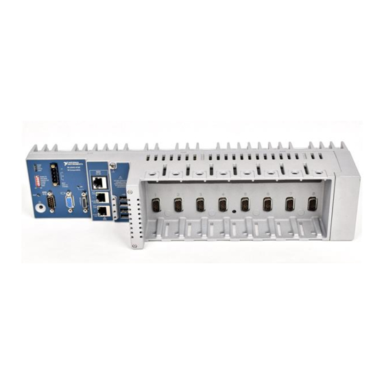
Ni compactdaq eight-slot controller
Hide thumbs
Also See for cDAQ-9138:
- Quick start (4 pages) ,
- Quick start manual (6 pages) ,
- User manual (140 pages)

Subscribe to Our Youtube Channel
Related Manuals for National Instruments cDAQ-9138


Summary of Contents for National Instruments cDAQ-9138
- Page 1 National Instruments cDAQ-9138 Manual Get Pricing & Availability at ApexWaves.com Call Today: 1-800-915-6216 Email: sales@apexwaves.com https://www.apexwaves.com/modular-systems/national-instruments/compactdaq/cDAQ-9138...
- Page 2 NI cDAQ -9138/9139 User Manual NI CompactDAQ Eight-Slot Controller NI cDAQ-9138/9139 User Manual March 2016 371042D-01...
- Page 3 11500 North Mopac Expressway Austin, Texas 78759-3504 USA Tel: 512 683 0100 For further support information, refer to the appendix. To comment on NI NI Services documentation, refer to the NI website at and enter the Info Code ni.com/info feedback © 2012–2016 National Instruments. All rights reserved.
- Page 4 National Instruments Corporation. National Instruments respects the intellectual property of others, and we ask our users to do the same. NI software is protected by copyright and other intellectual property laws. Where NI software may be used to reproduce software or other materials belonging to others, you may use NI software only to reproduce materials that you may reproduce in accordance with the terms of any applicable license or other legal restriction.
- Page 5 ™ The ExpressCard word mark and logos are owned by PCMCIA and any use of such marks by National Instruments is under license. The mark LabWindows is used under a license from Microsoft Corporation. Windows is a registered trademark of Microsoft Corporation in the United States and other countries.
-
Page 6: Table Of Contents
Safety Guidelines......................1-2 Electromagnetic Compatibility Guidelines ..............1-3 Hardware Symbol Definitions ..................1-3 Unpacking......................... 1-4 Installing the NI cDAQ-9138/9139 for Windows ............1-5 Installing the NI cDAQ-9138/9139 for LabVIEW Real-Time......... 1-8 Troubleshooting Network Communication in NI cDAQ-9138/9139 for LabVIEW Real-Time Controller................1-12 Wiring Power to the cDAQ Controller................ - Page 7 Contents Chapter 2 Analog Input Analog Input Triggering Signals ..................2-1 Analog Input Timing Signals.................... 2-1 AI Sample Clock Signal ...................2-2 Routing the Sample Clock to an Output Terminal ........... 2-2 AI Sample Clock Timebase Signal ................2-2 AI Convert Clock Signal Behavior For Analog Input Modules ....... 2-2 Scanned Modules....................
- Page 8 NI cDAQ-9138/9139 User Manual Chapter 4 Digital Input/Output and PFI Digital Input/Output ......................4-1 Serial DIO versus Parallel DIO Modules ..............4-1 Static DIO ......................... 4-2 Digital Input......................4-2 Digital Input Triggering Signals............... 4-2 Digital Input Timing Signals ................4-2 Digital Input Filters ..................
- Page 9 Contents High Frequency with Two Counters..............5-12 Large Range of Frequencies with Two Counters ..........5-13 Sample Clocked Buffered Frequency Measurement ........5-14 Choosing a Method for Measuring Frequency ..........5-15 Which Method Is Best?..................5-16 Period Measurement ....................5-18 Position Measurement....................
- Page 10 NI cDAQ-9138/9139 User Manual Counter n HW Arm Signal ..................5-36 Routing Signals to Counter n HW Arm Input ..........5-36 Counter n Sample Clock Signal................5-36 Using an Internal Source .................. 5-37 Using an External Source ................. 5-37 Routing Counter n Sample Clock to an Output Terminal ........ 5-37 Counter n Internal Output and Counter n TC Signals ..........
-
Page 11: Getting Started With The Cdaq Controller
The National Instruments CompactDAQ cDAQ-9138 controller features the 1.06 GHz Celeron processor. The National Instruments CompactDAQ cDAQ-9139 controller features the 1.33 GHz Intel Core i7 processor. The NI cDAQ-9138 and NI cDAQ-9139 are available as a Windows Embedded Standard 7 (WES7) or a LabVIEW Real-Time system. -
Page 12: Safety Guidelines
Product misuse can result in a hazard. You can compromise the safety protection built into the product if the product is damaged in any way. If the product is damaged, return it to National Instruments for repair. Because some C Series modules may have more stringent certification... -
Page 13: Electromagnetic Compatibility Guidelines
Furthermore, any modifications to the product not expressly approved by National Instruments could void your authority to operate it under your local regulatory rules. -
Page 14: Unpacking
At the end of the product life cycle, all products must be sent to EU Customers a WEEE recycling center. For more information about WEEE recycling centers, National Instruments WEEE initiatives, and compliance with WEEE Directive 2002/96/EC on Waste and Electronic Equipment, visit ni.com/environment/... -
Page 15: Installing The Ni Cdaq-9138/9139 For Windows
You will also require number 1 and number 2 Phillips screwdrivers to install and set up the cDAQ controller. You will need the following items to set up the NI cDAQ-9138/9139 for Windows controller: • Power connector (packaged with the cDAQ controller) •... - Page 16 Chapter 1 Getting Started with the cDAQ Controller Connect a computer keyboard and mouse to the bottom two USB ports on the cDAQ controller. Attach a ring lug to a 1.31 mm (16 AWG) or larger wire. Remove the ground screw from the ground terminal on the front panel.
- Page 17 NI cDAQ-9138/9139 User Manual Verify that the DISABLE RT DIP switch is in the ON position so that the controller boots into the Windows operating system. Refer to the section for more information DIP Switches about the DISABLE RT DIP switch.
-
Page 18: Installing The Ni Cdaq-9138/9139 For Labview Real-Time
ADE readme files for specific version compatibility). You will also require number 1 and number 2 Phillips screwdrivers to install and set up the cDAQ controller. You will need the following items to set up the NI cDAQ-9138/9139 for LabVIEW Real-Time controller: •... - Page 19 The NI-DAQmx driver software is included on the disk shipped with your kit and is available for download at . The documentation for NI-DAQmx is available after ni.com/support installation from Start»All Programs»National Instruments»NI-DAQ. Other NI documentation is available from ni.com/manuals Power on the host computer and connect it to an Ethernet network.
- Page 20 Chapter 1 Getting Started with the cDAQ Controller Verify that the DISABLE RT DIP switch is in the OFF position so that the controller will boot into LabVIEW Real-Time. Refer to the section for more information DIP Switches about the DISABLE RT DIP switch. Figure 1-4.
- Page 21 NI cDAQ-9138/9139 User Manual Stand-Alone Real-Time Application (RT Module) topic of the LabVIEW Help for more information about startup applications. After powerup, you can install software on the cDAQ controller. For RT Note systems, you can also change the network settings using Measurement & Automation Explorer (MAX) on a host computer.
-
Page 22: Troubleshooting Network Communication In Ni Cdaq-9138/9139 For Labview Real-Time Controller
Troubleshooting Network Communication in NI cDAQ-9138/9139 for LabVIEW Real-Time Controller If the controller cannot communicate with the network, you can use the IP RESET DIP switch to manually restore the controller to the default network settings. When you reboot the controller with the IP RESET DIP switch in the ON position, the controller attempts to connect to the network using DHCP. - Page 23 NI cDAQ-9138/9139 User Manual Do not connect V2 to a DC mains supply or to any supply requiring a Caution connecting cable longer than 3 m (10 ft). A DC mains supply is a local DC electricity supply network in the infrastructure of a site or building.
-
Page 24: Mounting The Cdaq Controller
Mounting the cDAQ Controller You can use the cDAQ controller on a desktop or mount it to a panel, wall, DIN rail, or rack. For accessory ordering information, refer to the pricing section of the NI cDAQ-9138/9139 product page at ni.com... - Page 25 For more information about how different mounting configurations can cause temperature derating, go to and enter the Info Code ni.com/info cdaqmounting Figure 1-9. NI cDAQ-9138/9139 Mounted Horizontally with Panel Mount Kit NI cDAQ-9139 cDAQ-9139 NI CompactDAQ NI CompactDAQ Figure 1-10. NI cDAQ-9138/9139 Temperature, Cooling, and Cabling Dimensions Cooling Outline 50.8 mm (2.00 in.)
-
Page 26: Using The Cdaq Controller On A Desktop
Chapter 1 Getting Started with the cDAQ Controller Your installation must meet the following requirements for space and Caution cabling clearance, as shown in Figure 1-10: • Allow 50.8 mm (2 in.) on the top and the bottom of the controller for air circulation. -
Page 27: Mounting The Cdaq Controller On A Panel
Fasten the mounting plate to the controller using a number 2 Phillips screwdriver and six M4 × 10 screws. National Instruments provides these screws with the panel mount kit. Tighten the screws to a maximum torque of 1.3 N · m (11.5 lb · in.). - Page 28 Chapter 1 Getting Started with the cDAQ Controller Figure 1-13. Installing the Mounting Plate on the cDAQ Controller Figure 1-14. Dimensions of the cDAQ Controller with Mounting Plate Installed 406.4 mm (16.00 in.) 387.4 mm (15.25 in.) 22.2 mm 9.5 mm (0.88 in.) (0.38 in.) 7.2 mm...
-
Page 29: Mounting The Cdaq Controller On A Din Rail
Fasten the DIN rail clip to the controller using a number 2 Phillips screwdriver and three M4 × 10 screws. National Instruments provides these screws with the DIN rail mount kit. Tighten the screws to a maximum torque of 1.3 N · m (11.5 lb · in.). Make sure the DIN rail kit is installed as shown in Figure 1-16, with the larger lip of the DIN clip positioned up. -
Page 30: Mounting The Cdaq Controller On A Rack
Chapter 1 Getting Started with the cDAQ Controller Figure 1-16. Installing the DIN Rail Clip on the cDAQ Controller Insert one edge of the DIN rail into the deeper opening of the DIN rail clip, as shown in Figure 1-17, and press down firmly on the controller to compress the spring until the clip locks in place on the DIN rail. -
Page 31: Removing Modules From The Cdaq Controller
The cDAQ controller video (VGA) port, shown in Figure 1-1, outputs graphics using VESA standard VGA analog signaling. Use this port to connect a monitor to program the NI cDAQ-9138/9139 for Windows. Table 1-3 lists the video port pin locations and VGA signals. -
Page 32: Usb Ports
USB devices to the , or drive, starting with the drive if it is available. You can also use these ports to connect a computer keyboard and mouse for cDAQ-9138/9139 for Windows programming. Go to and enter Info Code for up-to-date ni.com/info... -
Page 33: Ethernet Leds
You must use Ethernet port 1 to configure the (NI cDAQ-9138/9139 for LabVIEW Real-Time) NI cDAQ-9138/9139 for LabVIEW Real-Time; you cannot configure the controller through Ethernet port 2. To use Ethernet port 2, you must assign a static IP address to the port using MAX. -
Page 34: Ethernet Cabling
Chapter 1 Getting Started with the cDAQ Controller Table 1-5. Ethernet LED Indications (Continued) LED Color LED State Indication 10/100/ Yellow Solid 1,000 Mbit/s data rate selected 1000 Green Solid 100 Mbit/s data rate selected — 10 Mbit/s data rate selected Ethernet Cabling Table 1-6 shows the shielded Ethernet cable wiring connections for both straight through and crossover cables. -
Page 35: Rs-232 Serial Port
NI cDAQ-9138/9139 User Manual RS-232 Serial Port The cDAQ controller has an RS-232 serial port, shown in Figure 1-1, to which you can connect devices such as displays or input devices. Use the Serial VIs to read from and write to the serial port. -
Page 36: Mxi-Express Port
RIO expansion controller. Go to and enter Info Code ni.com/info for up-to-date information about supported NI devices for the NI cDAQ-9138/9139 exswh5 controller. Complete the following steps to connect one or more cDAQ controller to a MXI-Express device. - Page 37 Description DISABLE RT The position of the (NI cDAQ-9138/9139 for LabVIEW Real-Time) DISABLE RT determines the operating system the cDAQ controller boots into. If the switch is in the OFF position, the controller boots into LabVIEW RT. Move the switch to the ON position to boot the cDAQ controller from an external drive.
- Page 38 Description CONSOLE OUT The position of the (NI cDAQ-9138/9139 for LabVIEW Real-Time) CONSOLE OUT switch determines whether console input and output are redirected to the RS-232 serial port. If the switch is in the ON position, console input and output are redirected to the RS-232 serial port. If the switch is in the OFF position, the RS-232 serial port functions normally.
-
Page 39: Power Connector
Description NO APP Push the NO APP switch (NI cDAQ-9138/9139 for LabVIEW Real-Time) to the ON position to prevent a LabVIEW RT startup application from running at startup. If you want to permanently disable a LabVIEW RT application from running at startup, you must disable it in LabVIEW. -
Page 40: Leds
Chapter 1 Getting Started with the cDAQ Controller LEDs The cDAQ controller features four LEDs—POWER, DRIVE, STATUS, and USER1—on its front panel, two LEDs—ACT/LINK and 10/100/1000—near each Ethernet connector, and one LINK LED near the MXI-Express port. Refer to Figure 1-1 for the locations of the LEDs. Table 1-8 lists the LEDs and status indications. - Page 41 NI cDAQ-9138/9139 User Manual Table 1-8. LED Indications (Continued) Color LED State Indication STATUS Yellow 1 flash every Software error—The controller is unconfigured. Use few seconds MAX to configure the controller. Refer to the Measurement & Automation Explorer Help for information about configuring the controller.
-
Page 42: Cmos Battery And Cmos Reset Button
Ensure that the ambient operating temperature does not exceed the range specified in the Environmental section of the specifications document for your cDAQ controller. If the problem persists, contact National Instruments. — Normal operation. USER1 Green/ —... -
Page 43: Chassis Grounding Screw
NI cDAQ-9138/9139 User Manual Complete the following steps to reset the CMOS and reset the BIOS settings to factory default values: Disconnect power from the cDAQ controller. Press the CMOS reset button, shown in Figure 1-1, Controller, and NI cDAQ-9138/9139 hold it for 1 second. -
Page 44: Cpu Expansion Module (Cxm) Connector
Chapter 1 Getting Started with the cDAQ Controller If you use shielded cabling to connect to a C Series module with a plastic Note connector, you must attach the cable shield to the chassis grounding terminal using 1.31 mm (16 AWG) or larger wire. Use shorter wire for better EMC performance. CPU eXpansion Module (CXM) Connector In the future, the CXM connector will enable you to connect additional industry-standard I/O to the cDAQ controller. -
Page 45: Using The Cdaq Controller
MXI Express C Series Module National Instruments C Series modules provide built-in signal conditioning and screw terminal, spring terminal, BNC, D-SUB, or RJ-50 connectors. A wide variety of I/O types are available, allowing you to customize the cDAQ controller to meet your application needs. -
Page 46: Parallel Versus Serial Dio Modules
Chapter 1 Getting Started with the cDAQ Controller modules to your sensors/actuators. C Series modules can sometimes provide isolation from channel-to-earth ground and channel-to-channel. For more information about which C Series modules are compatible with the cDAQ controller, refer to the C Series Support in NI-DAQmx document by going to and entering ni.com/info the Info Code... -
Page 47: Processor And Ports
NI cDAQ-9138/9139 User Manual – section of Chapter 4, Digital Input Triggering Signals Digital Input/Output and PFI – section of Chapter 4, Digital Output Triggering Signals Digital Input/Output and PFI • Independent Data Streams—The cDAQ controller supports seven independent high-speed data streams, which allow for up to seven simultaneous hardware-timed tasks, such as analog input, analog output, buffered counter/timers, and hardware-timed digital input/output. -
Page 48: Analog Input
Analog Input Timing Signals The cDAQ controller features the following analog input timing signals: • AI Sample Clock Signal* • AI Sample Clock Timebase Signal • AI Start Trigger Signal* © National Instruments | 2-1... -
Page 49: Ai Sample Clock Signal
NI cDAQ-9138/9139 User Manual • AI Reference Trigger Signal* • AI Pause Trigger Signal* Signals with an * support digital filtering. Refer to the section of Chapter 4, PFI Filters Digital PFI, for more information. Input/Output and Refer to the... -
Page 50: Scanned Modules
Chapter 2 Analog Input Scanned Modules Scanned C Series analog input modules contain a single A/D converter and a multiplexer to select between multiple input channels. When the cDAQ Module Interface receives a Sample Clock pulse, it begins generating a Convert Clock for each scanned module in the current task. Each Convert Clock signals the acquisition of a single channel from that module. -
Page 51: Slow Sample Rate Modules
NI cDAQ-9138/9139 User Manual Because of the filtering used in sigma-delta A/D converters, these modules usually exhibit a fixed input delay relative to non-sigma-delta modules in the system. This input delay is specified in the C Series module documentation. Slow Sample Rate Modules Some C Series analog input modules are specifically designed for measuring signals that vary slowly, such as temperature. -
Page 52: Using A Digital Source
Chapter 2 Analog Input An acquisition that uses a start trigger (but not a reference trigger) is sometimes referred to as a posttriggered acquisition. That is, samples are measured only after the trigger. When you are using an internal sample clock, you can specify a default delay from the start trigger to the first sample. -
Page 53: Using A Digital Source
NI cDAQ-9138/9139 User Manual Pretriggered Acquisition be Continuous?, for more information. To access this KnowledgeBase, go to and enter the Info Code ni.com/info rdcanq When the reference trigger occurs, the cDAQ controller continues to write samples to the buffer until the buffer contains the number of posttrigger samples desired. Figure 2-3 shows the final buffer. -
Page 54: Ai Pause Trigger Signal
Chapter 2 Analog Input AI Pause Trigger Signal You can use the Pause Trigger to pause and resume a measurement acquisition. The internal sample clock pauses while the external trigger signal is active and resumes when the signal is inactive. You can program the active level of the pause trigger to be high or low. Using a Digital Source To use the Pause Trigger, specify a source and a polarity. -
Page 55: Analog Output
You can configure software-timed generations to simultaneously update • Only one simultaneous update task can run at a time • A hardware-timed AO task and a simultaneous update AO task cannot run at the same time © National Instruments | 3-1... -
Page 56: Hardware-Timed Generations
Chapter 3 Analog Output Hardware-Timed Generations With a hardware-timed generation, a digital hardware signal controls the rate of the generation. This signal can be generated internally on the controller or provided externally. Hardware-timed generations have several advantages over software-timed acquisitions: •... -
Page 57: Analog Output Triggering Signals
NI cDAQ-9138/9139 User Manual Analog Output Triggering Signals Analog output supports two different triggering actions: AO Start Trigger and AO Pause Trigger. An analog or digital trigger can initiate these actions. Up to two C Series parallel digital input modules can be used in any controller slot to supply a digital trigger. An analog trigger can be supplied by some C Series analog modules. -
Page 58: Routing Ao Sample Clock To An Output Terminal
Chapter 3 Analog Output Routing AO Sample Clock to an Output Terminal You can route AO Sample Clock to any output PFI terminal. AO Sample Clock is active high by default. AO Sample Clock Timebase Signal The AO Sample Clock Timebase (ao/SampleClockTimebase) signal is divided down to provide a source for AO Sample Clock. -
Page 59: Routing Ao Start Trigger Signal To An Output Terminal
NI cDAQ-9138/9139 User Manual Routing AO Start Trigger Signal to an Output Terminal You can route AO Start Trigger to any output PFI terminal. The output is an active high pulse. AO Pause Trigger Signal Use the AO Pause Trigger signal (ao/PauseTrigger) to mask off samples in a DAQ sequence. -
Page 60: Minimizing Glitches On The Output Signal
Chapter 3 Analog Output When you use an analog trigger source, the samples are paused when the Analog Comparison Event signal is at a high or low level, depending on the trigger properties. The analog trigger circuit must be configured by a simultaneously running analog input task. Depending on the C Series module capabilities, you may need two modules Note to utilize analog triggering. -
Page 61: Digital Input/Output And Pfi
You can only do hardware timing in one direction at a time on a serial bidirectional module. To determine the capability of digital I/O modules supported by the cDAQ controller, refer to the C Series Support in NI-DAQmx document by going to and entering the Info ni.com/info Code rdcdaq © National Instruments | 4-1... -
Page 62: Static Dio
Chapter 4 Digital Input/Output and PFI Static DIO Each of the DIO lines can be used as a static DI or DO line. You can use static DIO lines to monitor or control digital signals on some C Series modules. Each DIO line can be individually configured as a digital input (DI) or digital output (DO), if the C Series module being used allows such configuration. - Page 63 NI cDAQ-9138/9139 User Manual DI Sample Clock Signal Use the DI Sample Clock (di/SampleClock) signal to sample digital I/O on any slot using parallel digital modules, and store the result in the DI waveform acquisition FIFO. If the cDAQ controller receives a DI Sample Clock signal when the FIFO is full, it reports an overflow error to the host software.
- Page 64 Chapter 4 Digital Input/Output and PFI Using an External Source You can route the following signals as DI Sample Clock: • Any PFI terminal • Analog Comparison Event (an analog trigger) You can sample data on the rising or falling edge of DI Sample Clock. Routing DI Sample Clock to an Output Terminal You can route DI Sample Clock to any output PFI terminal.
- Page 65 NI cDAQ-9138/9139 User Manual Routing DI Start Trigger to an Output Terminal You can route DI Start Trigger to any output PFI terminal. The output is an active high pulse. DI Reference Trigger Signal Use a reference trigger (di/ReferenceTrigger) signal to stop a measurement acquisition. To use a reference trigger, specify a buffer of finite size and a number of pretrigger samples (samples that occur before the reference trigger).
-
Page 66: Digital Input Filters
Chapter 4 Digital Input/Output and PFI When you use an analog trigger source, the acquisition stops on the first rising or falling edge of the Analog Comparison Event signal, depending on the trigger properties. Depending on the C Series module capabilities, you may need two modules Note to utilize analog triggering. -
Page 67: Getting Started With Di Applications In Software
NI cDAQ-9138/9139 User Manual In NI-DAQmx, the filter is programmed by setting the minimum pulse width, Tp , that will pass the filter, and is selectable in 25 ns increments. The appropriate Filter Clock is selected by the driver. Pulses of length less than 1/2 Tp will be rejected, and the filtering behavior of lengths between 1/2 Tp and 1 Tp are not defined because they depend on the phase of the Filter Clock relative to the input signal. -
Page 68: Digital Output
Chapter 4 Digital Input/Output and PFI Change detection acquisitions can be buffered or nonbuffered: • Nonbuffered Change Detection Acquisition—In a nonbuffered acquisition, data is transferred from the cDAQ controller directly to a PC buffer. • Buffered Change Detection Acquisition—A buffer is a temporary storage in computer memory for acquired samples. -
Page 69: Digital Output Triggering Signals
NI cDAQ-9138/9139 User Manual Hardware-timed generations have several advantages over software-timed acquisitions: • The time between samples can be much shorter. • The timing between samples is deterministic. • Hardware-timed acquisitions can use hardware triggering. Hardware-timed DO operations on the cDAQ controller must be buffered. -
Page 70: Digital Output Timing Signals
Chapter 4 Digital Input/Output and PFI A digital or analog trigger can initiate these actions. Any PFI terminal can supply a digital trigger, and some C Series analog modules can supply an analog trigger. For more information, refer to the documentation included with your C Series module(s). Refer to the sections for more DO Start Trigger Signal... - Page 71 NI cDAQ-9138/9139 User Manual DO Start Trigger Signal Use the DO Start Trigger (do/StartTrigger) signal to initiate a waveform generation. If you do not use triggers, you can begin a generation with a software command. If you are using an internal sample clock, you can specify a delay from the start trigger to the first sample.
- Page 72 Chapter 4 Digital Input/Output and PFI Figure 4-5. DO Pause Trigger with the Onboard Clock Source Pause Trigger Sample Clock If you are using any signal other than the onboard clock as the source of the sample clock, the generation resumes as soon as the pause trigger is deasserted and another edge of the sample clock is received, as shown in Figure 4-6.
-
Page 73: Getting Started With Do Applications In Software
NI cDAQ-9138/9139 User Manual Getting Started with DO Applications in Software You can use the cDAQ controller in the following digital output applications: • Single-point (on-demand) generation • Finite generation • Continuous generation For more information about programming digital output applications and triggers in software, refer the LabVIEW Help or to the NI-DAQmx Help. - Page 74 Chapter 4 Digital Input/Output and PFI on N consecutive edges, the low-to-high transition is propagated to the rest of the circuit. The value of N depends on the filter setting, as shown in Table 4-1. Table 4-1. Selectable PFI Filter Settings Min Pulse Filter Width...
-
Page 75: Counters
(Embedded Ctrn) for use in what are traditionally two-counter measurements and generations. The embedded counters cannot be programmed independent of the main counter; signals from the embedded counters are not routable. © National Instruments | 5-1... -
Page 76: Counter Timing Engine
Chapter 5 Counters Counter Timing Engine Unlike analog input, analog output, digital input, and digital output, the cDAQ controller counters do not have the ability to divide down a timebase to produce an internal counter sample clock. For sample clocked operations, an external signal must be provided to supply a clock source. -
Page 77: Counter Input Applications
NI cDAQ-9138/9139 User Manual Table 5-1. Counter Timing Measurements (Continued) Implicit Sample Clocked Measurement Timing Support Timing Support Buffered Position Buffered Two-Signal Edge Separation Counter Input Applications The following sections list the various counter input applications available on the cDAQ controller: •... -
Page 78: Buffered (Sample Clock) Edge Counting
Chapter 5 Counters You also can use a pause trigger to pause (or gate) the counter. When the pause trigger is active, the counter ignores edges on its Source input. When the pause trigger is inactive, the counter counts edges normally. You can route the pause trigger to the Gate input of the counter. -
Page 79: Pulse-Width Measurement
NI cDAQ-9138/9139 User Manual • Count up when the Counter 0 B input is high; count down when it is low For information about connecting counter signals, refer to the Default Counter/Timer Routing section. Pulse-Width Measurement In pulse-width measurements, the counter measures the width of a pulse on its Gate input signal. -
Page 80: Implicit Buffered Pulse-Width Measurement
Chapter 5 Counters Implicit Buffered Pulse-Width Measurement An implicit buffered pulse-width measurement is similar to single pulse-width measurement, but buffered pulse-width measurement takes measurements over multiple pulses. The counter counts the number of edges on the Source input while the Gate input remains active. On each trailing edge of the Gate signal, the counter stores the count in the counter FIFO. -
Page 81: Pulse Measurement
NI cDAQ-9138/9139 User Manual Pulse Measurement In pulse measurements, the counter measures the high and low time of a pulse on its Gate input signal after the counter is armed. A pulse is defined in terms of its high and low time, high and low ticks or frequency and duty cycle. -
Page 82: Sample Clocked Buffered Pulse Measurement
Chapter 5 Counters Figure 5-9 shows an example of an implicit buffered pulse measurement. Figure 5-9. Implicit Buffered Pulse Measurement Counter Armed Gate Source Buffer Sample Clocked Buffered Pulse Measurement A sample clocked buffered pulse measurement is similar to single pulse measurement, but a buffered pulse measurement takes measurements over multiple pulses correlated to a sample clock. -
Page 83: Single Semi-Period Measurement
NI cDAQ-9138/9139 User Manual You can route an internal or external periodic clock signal (with a known period) to the Source input of the counter. The counter counts the number of rising (or falling) edges occurring on the Source input between two edges of the Gate signal. -
Page 84: Pulse Versus Semi-Period Measurements
Chapter 5 Counters Pulse versus Semi-Period Measurements In hardware, pulse measurement and semi-period are the same measurement. Both measure the high and low times of a pulse. The functional difference between the two measurements is how the data is returned. In a semi-period measurement, each high or low time is considered one point of data and returned in units of seconds or ticks. -
Page 85: Low Frequency With One Counter
NI cDAQ-9138/9139 User Manual Low Frequency with One Counter For low frequency measurements with one counter, you measure one period of your signal using a known timebase. You can route the signal to measure (fx) to the Gate of a counter. You can route a known timebase (fk) to the Source of the counter. -
Page 86: High Frequency With Two Counters
Chapter 5 Counters High Frequency with Two Counters For high frequency measurements with two counters, you measure one pulse of a known width using your signal and derive the frequency of your signal from the result. Counter 0 is always paired with Counter 1. Counter 2 is always paired with Note Counter 3. - Page 87 NI cDAQ-9138/9139 User Manual Large Range of Frequencies with Two Counters By using two counters, you can accurately measure a signal that might be high or low frequency. This technique is called reciprocal frequency measurement. When measuring a large range of frequencies with two counters, you generate a long pulse using the signal to measure.
- Page 88 Chapter 5 Counters Sample Clocked Buffered Frequency Measurement Sample clocked buffered point frequency measurements can either be a single frequency measurement or an average between sample clocks. Use CI.Freq.EnableAveraging to set the behavior. For buffered frequency, the default is True. A sample clocked buffered frequency measurement with CI.Freq.EnableAveraging set to True uses the embedded counter and a sample clock to perform a frequency measurement.
-
Page 89: Choosing A Method For Measuring Frequency
NI cDAQ-9138/9139 User Manual Choosing a Method for Measuring Frequency The best method to measure frequency depends on several factors including the expected frequency of the signal to measure, the desired accuracy, how many counters are available, and how long the measurement can take. For all frequency measurement methods, assume the... -
Page 90: Which Method Is Best
Chapter 5 Counters Table 5-2. Frequency Measurement Methods Two Counter High Variable Sample Clocked One Counter Frequency Large Range Known timebase Known Known timebase timebase ------------------------------- gating period gating period Measurement time --- - --- - --- - Max. ------------------------------ - ... - Page 91 NI cDAQ-9138/9139 User Manual Table 5-3. 50 kHz Frequency Measurement Methods (Continued) Two Counter Sample High Variable Clocked One Counter Frequency Large Range Max. frequency .638 31.27 1,000 .625 error (Hz) Max. error % .00128 .0625 .00125 From this, you can see that while the measurement time for one counter is shorter, the accuracy is best in the sample clocked and two counter large range measurements.
-
Page 92: Period Measurement
Chapter 5 Counters must be at least twice the sample clock rate to ensure that a full period of the frequency to be measured occurs between sample clocks. • Low frequency measurements with one counter is a good method for many applications. However, the accuracy of the measurement decreases as the frequency increases. -
Page 93: Position Measurement
NI cDAQ-9138/9139 User Manual You can route an internal or external periodic clock signal (with a known period) to the Source input of the counter. The counter counts the number of rising (or falling) edges occurring on the Source input between the two active edges of the Gate signal. -
Page 94: Channel Z Behavior
Chapter 5 Counters Figure 5-18. X2 Encoding Ch A Ch B Counter Value 5 • X4 Encoding—Similarly, the counter increments or decrements on each edge of channels A and B for X4 encoding. Whether the counter increments or decrements depends on which channel leads the other. -
Page 95: Measurements Using Two Pulse Encoders
NI cDAQ-9138/9139 User Manual Figure 5-20. Channel Z Reload with X4 Decoding Ch A Ch B Ch Z Max Timebase Counter Value A = 0 B = 0 Z = 1 Measurements Using Two Pulse Encoders The counter supports two pulse encoders that have two channels—channels A and B. -
Page 96: Two-Signal Edge-Separation Measurement
Chapter 5 Counters Figure 5-22. Buffered Position Measurement Counter Armed Sample Clock (Sample on Rising Edge) Ch A Ch B Count Buffer Two-Signal Edge-Separation Measurement Two-signal edge-separation measurement is similar to pulse-width measurement, except that there are two measurement signals—Aux and Gate. An active edge on the Aux input starts the counting and an active edge on the Gate input stops the counting. -
Page 97: Implicit Buffered Two-Signal Edge-Separation Measurement
NI cDAQ-9138/9139 User Manual Figure 5-23 shows an example of a single two-signal edge-separation measurement. Figure 5-23. Single Two-Signal Edge-Separation Measurement Counter Armed Measured Interval GATE SOURCE Counter Value Latched Value Implicit Buffered Two-Signal Edge-Separation Measurement Implicit buffered and single two-signal edge-separation measurements are similar, but implicit buffered measurement measures multiple intervals. -
Page 98: Counter Output Applications
Chapter 5 Counters Figure 5-25. Sample Clocked Buffered Two-Signal Separation Measurement Sample Clock GATE SOURCE Counter Value Buffer If an active edge on the Gate and an active edge on the Aux does not occur Note between sample clocks, an overrun error occurs. For information about connecting counter signals, refer to the Default Counter/Timer Routing section. -
Page 99: Single Pulse Generation With Start Trigger
NI cDAQ-9138/9139 User Manual You can specify a pulse width. The pulse width is also measured in terms of a number of active edges of the Source input. You also can specify the active edge of the Source input (rising or falling). -
Page 100: Finite Pulse Train Generation
Chapter 5 Counters • Continuous Buffered Implicit Pulse Train Generation • Finite Buffered Sample Clocked Pulse Train Generation • Continuous Buffered Sample Clocked Pulse Train Generation Finite Pulse Train Generation This function generates a train of pulses with programmable frequency and duty cycle for a predetermined number of pulses. -
Page 101: Continuous Pulse Train Generation
NI cDAQ-9138/9139 User Manual Figure 5-29. Retriggerable Single Pulse Generation with Initial Delay on Retrigger Counter Load Values 4 3 2 1 0 2 1 0 4 3 2 1 0 2 1 0 GATE (Start Trigger) SOURCE Figure 5-30 shows the same pulse train with CO.EnableInitialDelayOnRetrigger set to the default False. -
Page 102: Buffered Pulse Train Generation
Chapter 5 Counters Figure 5-31 shows a continuous pulse train generation (using the rising edge of Source). Figure 5-31. Continuous Pulse Train Generation SOURCE Counter Armed Continuous pulse train generation is sometimes called frequency division. If the high and low pulse widths of the output signal are M and N periods, then the frequency of the Counter n Internal Output signal is equal to the frequency of the Source input divided by M + N. -
Page 103: Continuous Buffered Implicit Pulse Train Generation
NI cDAQ-9138/9139 User Manual Table 5-6. Finite Implicit Buffered Pulse Train Generation Sample Idle Ticks Active Ticks Figure 5-32. Finite Implicit Buffered Pulse Train Generation SOURCE Counter Armed Continuous Buffered Implicit Pulse Train Generation This function generates a continuous train of pulses with variable idle and active times. Instead of generating a set number of data samples and stopping, a continuous generation continues until you stop the operation. -
Page 104: Continuous Buffered Sample Clocked Pulse Train Generation
Chapter 5 Counters Table 5-7. Finite Buffered Sample Clocked Pulse Train Generation Sample Idle Ticks Active Ticks Figure 5-33. Finite Buffered Sample Clocked Pulse Train Generation Counter Armed Sample Clock Counter 2 1 0 1 0 1 0 1 2 1 0 2 1 0 2 1 0 2 1 0 1 0 0 2 1 0 2 1 Load Values... -
Page 105: Frequency Generation
NI cDAQ-9138/9139 User Manual Frequency Generation You can generate a frequency by using a counter in pulse train generation mode or by using the frequency generator circuit, as described in the section. Using the Frequency Generator Using the Frequency Generator The frequency generator can output a square wave at many different frequencies. -
Page 106: Frequency Division
Chapter 5 Counters For information about connecting counter signals, refer to the Default Counter/Timer Routing section. Frequency Division The counters can generate a signal with a frequency that is a fraction of an input signal. This function is equivalent to continuous pulse train generation. Refer to the Continuous Pulse Train section for detailed information. -
Page 107: Counter Timing Signals
NI cDAQ-9138/9139 User Manual Counter Timing Signals The cDAQ controller features the following counter timing signals: • Counter n Source Signal • Counter n Gate Signal • Counter n Aux Signal • Counter n A Signal • Counter n B Signal •... -
Page 108: Routing A Signal To Counter N Source
Chapter 5 Counters Table 5-8. Counter Applications and Counter n Source (Continued) Application Purpose of Source Terminal Buffered Edge Counting Input Terminal Two-Edge Separation Counter Timebase Routing a Signal to Counter n Source Each counter has independent input selectors for the Counter n Source signal. Any of the following signals can be routed to the Counter n Source input: •... -
Page 109: Routing Counter N Gate To An Output Terminal
NI cDAQ-9138/9139 User Manual • Change Detection Event • Analog Comparison Event In addition, a counter’s Internal Output or Source can be routed to a different counter’s gate. Some of these options may not be available in some driver software. Refer to the Device Routing in MAX topic in the NI-DAQmx Help or the LabVIEW Help for more information about available routing options. -
Page 110: Routing Counter N Z Signal To An Output Terminal
Chapter 5 Counters Routing Counter n Z Signal to an Output Terminal You can route Counter n Z out to any PFI terminal. Counter n Up_Down Signal Counter n Up_Down is another name for the Counter n B signal. Counter n HW Arm Signal The Counter n HW Arm signal enables a counter to begin an input or output function. -
Page 111: Using An Internal Source
NI cDAQ-9138/9139 User Manual Using an Internal Source To use Counter n Sample Clock with an internal source, specify the signal source and the polarity of the signal. The source can be any of the following signals: • DI Sample Clock •... -
Page 112: Routing Frequency Output To A Terminal
Chapter 5 Counters Routing Frequency Output to a Terminal You can route Frequency Output to any PFI terminal. Default Counter/Timer Routing Counter/timer signals are available to parallel digital I/O C Series modules. To determine the signal routing options for modules installed in your system, refer to the Device Routes tab in MAX. -
Page 113: Other Counter Features
NI cDAQ-9138/9139 User Manual Other Counter Features The following sections list the other counter features available on the cDAQ controller. Cascading Counters You can internally route the Counter n Internal Output and Counter n TC signals of each counter to the Gate inputs of the other counter. By cascading two counters together, you can effectively create a 64-bit counter. -
Page 114: 80 Mhz Source Mode
Chapter 5 Counters 80 MHz Source Mode In 80 MHz source mode, the controller synchronizes signals on the rising edge of the source, and counts on the third rising edge of the source. Edges are pipelined so no counts are lost, as shown in Figure 5-38. -
Page 115: Digital Routing And Clock Generation
Device Routes tab in MAX. Clock Routing Figure 6-1 shows the clock routing circuitry of the cDAQ controller. Figure 6-1. Clock Routing Circuitry 80 MHz Timebase 80 MHz Timebase ÷ 20 MHz Timebase ÷ 100 kHz Timebase © National Instruments | 6-1... -
Page 116: 80 Mhz Timebase
Chapter 6 Digital Routing and Clock Generation 80 MHz Timebase You can use the 80 MHz Timebase as the Source input to the 32-bit general-purpose counter/timers. 20 MHz Timebase The 20 MHz Timebase normally generates many of the AI and AO timing signals. It can function as the Source input to the 32-bit general-purpose counter/timers. -
Page 117: Controller Operating System And Configuration
Controller Operating System and Configuration This appendix covers the following topics regarding the NI cDAQ-9138/9139 integrated controller configurations: • Power-On Self Test (POST) Warning Messages • Restoring the Hard Drive to Factory Default Condition (Windows Only) • Installing an Operating System •... - Page 118 CD/DVD-ROM drive, connected to one of the USB ports, to install a different operating system such as Windows Embedded Standard 7 (WES7). For more information about installing an operating system on the NI cDAQ-9138/9139, go to and enter the Info Code ni.com/info...
- Page 119 NI cDAQ-9138/9139 User Manual • Boot Setup Menu • Security Menu • Save & Exit Menu Changing BIOS settings can cause incorrect controller behavior, including failure to boot. In general, do not change a setting unless you are absolutely sure what the setting does. Refer to...
- Page 120 Appendix A Controller Operating System and Configuration Table A-1. BIOS Setup Utility Keyboard Navigation (Continued) Key(s) Function(s) <F9> Loads the optimal default values for all BIOS configuration settings. The optimal default values are the same as the shipping configuration default values. <F10>...
- Page 121 NI cDAQ-9138/9139 User Manual • Submenu—Use this setting to access the Video Configuration Video Configuration submenu. • Submenu—Use this setting to access the Power/Wake Power/Wake Configuration Configuration submenu. • Submenu—Use this setting to access the USB Configuration submenu. USB Configuration •...
- Page 122 Appendix A Controller Operating System and Configuration Video Configuration Submenu Use this submenu to apply alternate settings to the video configuration. Normally, you do not need to modify these settings, as the factory default settings provide the most compatible and optimal configuration possible.
- Page 123 NI cDAQ-9138/9139 User Manual • Transfer Timeout—This setting specifies the number of seconds the POST waits for a USB mass storage device to complete a transaction. The default is 20 seconds. • Device Reset Timeout—This setting specifies the number of seconds the POST waits for a USB mass storage device to start.
- Page 124 Appendix A Controller Operating System and Configuration • COM 2 (RS-485/422)—This setting enables or disables the onboard RS-485/422 serial port. The default value is Enabled. • Device Settings—This item displays the current base address and interrupt request level (IRQ) information for the onboard RS-485/422 serial port. Serial Port Console Redirection Submenu Use this submenu to access configuration information related to console redirection.
- Page 125 LabVIEW RT Options Setup Menu Use this menu to configure boot options for (NI cDAQ-9138/9139 for LabVIEW Real-Time) LabVIEW RT if it is installed on the controller. If you are not using LabVIEW RT, you should leave these settings at default.
- Page 126 Appendix A Controller Operating System and Configuration Boot Setup Menu Use this menu to configure settings related to the boot process and boot device priority. • Submenu—Use this setting to access the Boot Settings Boot Settings Configuration Configuration submenu. • SCSI Drive Boot—This setting specifies whether or not boot support is enabled for legacy mass storage devices, such as SCSI drives.
- Page 127 NI cDAQ-9138/9139 User Manual Boot Settings Configuration Submenu Use this submenu to apply alternate configurations to boot settings. Normally, you do not need to modify these settings, as the factory default settings provide the most compatible and optimal configuration. •...
- Page 128 Appendix A Controller Operating System and Configuration power-on password and must be entered to boot or enter the BIOS setup utility. In the BIOS setup utility, the User has Administrator rights. By default, no password is specified. Save & Exit Menu The Save &...
- Page 129 LabVIEW Real-Time 2012 and version 15.1 or later of other NI application software. NI cDAQ Controller Documentation The NI cDAQ-9138/9139 for Windows Quick Start, packaged with your cDAQ controller preloaded with Windows Embedded Standard 7 software, describes how to set up and install the cDAQ controller and C Series modules, and how to confirm that your device is operating properly.
- Page 130 Appendix B Where to Go from Here The NI cDAQ-9138 Safety, Environmental, and Regulatory Information or NI cDAQ-9139 Safety, Environmental, and Regulatory Information includes important hazardous locations information, compliance precautions, and connection information for your cDAQ controller. Go and search for your cDAQ controller.
- Page 131 VIs, set up RT targets, and build, debug, and deploy real-time applications. Open the Getting Started with the LabVIEW Real-Time Module document by selecting Start»All Programs»National Instruments»LabVIEW»LabVIEW Manuals or by navigating to the directory and opening labview\manuals RT_Getting_Started.pdf...
- Page 132 • System Integration—If you have time constraints, limited in-house technical resources, or other project challenges, National Instruments Alliance Partner members can help. To learn more, call your local NI office or visit ni.com/alliance © National Instruments | C-1...
- Page 133 You also can visit the Worldwide Offices section of to access the branch ni.com/niglobal office websites, which provide up-to-date contact information, support phone numbers, email addresses, and current events. © National Instruments | C-2...
- Page 134 AO Start Trigger, 3-4 (LabVIEW Real-Time), 1-8 applications installation and configuration (Windows counter input, 5-3 Embedded Standard 7), 1-5 counter output, 5-24 mounting, 1-14 edge counting, 5-3 NI cDAQ-9138/9139, 1-2 arm start trigger, 5-38 removing modules, 1-21 © National Instruments | I-1...
- Page 135 NI cDAQ-9138/9139 User Manual troubleshooting network single pulse generation, 5-24 communication, 1-12 with start trigger, 5-25 unpacking, 1-4 synchronization modes, 5-39 using, 1-35 timing signals, 5-33 wiring power, 1-12 triggering, 5-38 cDAQ module interface, 1-36 counting edges, 5-3 CFast SSD module, 1-34...
- Page 136 Index DO Sample Clock, 4-10 generator, 5-31 DO Sample Clock Timebase, 4-10 measurement, 5-10 DO Start Trigger, 4-11 Frequency Output signal, 5-37 DIN rail mounting, 1-19 DIP switches, 1-26 DISABLE RT DIP switch, 1-27 generations documentation, related documentation, B-1 analog output data, 3-1 DRIVE LED, 1-30 buffered hardware-timed analog output, 3-2...
- Page 137 NI cDAQ-9138/9139 User Manual installation measuring cDAQ-9138/9139 for LabVIEW high frequency with two counters, 5-12 Real-Time, 1-8 large range of frequencies using two cDAQ-9138/9139 for Windows, 1-5 counters, 5-13 operating system, A-2 low frequency, 5-11 Intel AMT configuration submenu, A-7...
- Page 138 Index RS-232 serial, 1-25 sample clock RS-485/422 serial, 1-25 edge counting, 5-4 USB, 1-22 measurement, 5-21 video (VGA), 1-21 SATA configuration submenu, A-5 position measurement, 5-19 save and exit menu, A-12 buffered, 5-21 security menu, A-11 POWER semi-period measurement, 5-8 button, 1-29 implicit buffered, 5-9 LED, 1-30...
- Page 139 NI cDAQ-9138/9139 User Manual power/wake configuration, A-6 SATA configuration, A-5 video serial port configuration, A-7 (VGA) port, 1-21 serial port console redirection, A-8 configuration submenu, A-6 USB configuration, A-6 video configuration, A-6 synchronization modes, 5-39 wall mounting, 1-17 100 MHz source, 5-40...
Need help?
Do you have a question about the cDAQ-9138 and is the answer not in the manual?
Questions and answers