National Instruments cDAQ-9133 User Manual
Ni compactdaq controller
Hide thumbs
Also See for cDAQ-9133:
- Quick start manual (6 pages) ,
- Quick start (5 pages) ,
- User manual (140 pages)

Related Manuals for National Instruments cDAQ-9133


Summary of Contents for National Instruments cDAQ-9133
- Page 1 NI cDAQ -9132/9133/9134/ 9135/9136/9137 User Manual NI CompactDAQ Controller NI cDAQ-9132/9133/9134/9135/9136/9137 User Manual January 2019 371800E-01...
- Page 2 11500 North Mopac Expressway Austin, Texas 78759-3504 USA Tel: 512 683 0100 For further support information, refer to the Technical Support and Professional Services appendix. To comment on National Instruments documentation, refer to the National Instruments Web site at and enter the Info Code ni.com/info...
- Page 3 National Instruments Corporation. National Instruments respects the intellectual property of others, and we ask our users to do the same. NI software is protected by copyright and other intellectual property laws. Where NI software may be used to reproduce software or other materials belonging to others, you may use NI software only to reproduce materials that you may reproduce in accordance with the terms of any applicable license or other legal restriction.
- Page 4 ™ The ExpressCard word mark and logos are owned by PCMCIA and any use of such marks by National Instruments is under license. The mark LabWindows is used under a license from Microsoft Corporation. Windows is a registered trademark of Microsoft Corporation in the United States and other countries.
-
Page 5: Table Of Contents
SD Card LEDs ....................1-40 SD Card Slot Cover ..................1-40 USER1 Button ......................1-41 Chassis Grounding Screw..................1-41 CMOS Battery and CMOS Reset Button ..............1-41 Resetting the System CMOS and BIOS Settings ..........1-41 © National Instruments | v... - Page 6 Contents Cables and Accessories..................... 1-42 Using the cDAQ Controller ....................1-44 C Series Module......................1-45 Parallel versus Serial DIO Modules..............1-45 cDAQ Module Interface ...................1-45 STC3 ......................... 1-45 Processor and Ports ....................1-46 Chapter 2 Analog Input Analog Input Triggering Signals ..................2-1 Analog Input Timing Signals....................
- Page 7 Single Point (On-Demand) Edge Counting ............5-3 Buffered (Sample Clock) Edge Counting............5-4 Controlling the Direction of Counting.............. 5-5 Pulse-Width Measurement ..................5-5 Single Pulse-Width Measurement ..............5-5 Implicit Buffered Pulse-Width Measurement........... 5-6 Sample Clocked Buffered Pulse-Width Measurement ........5-6 © National Instruments | vii...
- Page 8 Contents Pulse Measurement ....................5-7 Single Pulse Measurement................5-8 Implicit Buffered Pulse Measurement .............. 5-8 Sample Clocked Buffered Pulse Measurement ..........5-9 Semi-Period Measurement..................5-9 Single Semi-Period Measurement ..............5-10 Implicit Buffered Semi-Period Measurement...........5-10 Pulse versus Semi-Period Measurements ............5-10 Frequency Measurement...................5-11 Low Frequency with One Counter..............
- Page 9 External or Internal Source Less than 20 MHz ..........5-40 Chapter 6 Digital Routing and Clock Generation Digital Routing ......................... 6-1 Clock Routing........................6-1 80 MHz Timebase ....................6-2 20 MHz Timebase ....................6-2 100 kHz Timebase ....................6-2 © National Instruments | ix...
- Page 10 Contents Appendix A Controller Operating System and BIOS Configuration Appendix B Where to Go from Here Appendix C Technical Support and Professional Services Index x | ni.com...
-
Page 11: Getting Started With The Cdaq Controller
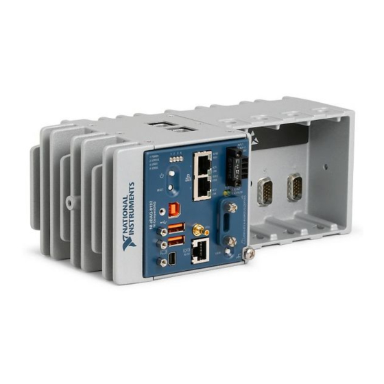
Controller The National Instruments four-slot CompactDAQ cDAQ-9132, cDAQ-9134, and cDAQ-9136 controllers and the eight-slot CompactDAQ cDAQ-9133, cDAQ-9135, and cDAQ-9137 controllers are available as a Windows Embedded Standard 7 (WES7) or a LabVIEW Real-Time system. NI cDAQ-9132/9133/9134/9135 controllers feature the dual-core 1.33 GHz Intel Atom processor. - Page 12 Chapter 1 Getting Started with the cDAQ Controller Figure 1-1 shows the NI cDAQ-9132/9134/9136 controller. Figure 1-2 shows the NI cDAQ-9133/9135/9137 controller. Figure 1-1. NI cDAQ-9132/9134/9136 Controller 1: POWER 1 2 3 4 INPUT 2: STATUS 9–30V 10/100 40W MAX...
-
Page 13: Safety Guidelines
NI cDAQ-9132/9133/9134/9135/9136/9137 User Manual Figure 1-2. NI cDAQ-9133/9135/9137 Controller NI 9263 NI 9263 NI 9263 NI 9263 POWER, STATUS, USER1, and USER2 LEDs SD Card Removable Storage SD Card Slot NI-XNET CAN/LIN Connector (cDAQ-9135 Only) Cover Mounting Holes RJ-45 Ethernet Ports 1 and... -
Page 14: Electromagnetic Compatibility Guidelines
Furthermore, any modifications to the product not expressly approved by National Instruments could void your authority to operate it under your local regulatory rules. -
Page 15: Special Guidelines For Marine Applications
EU Customers At the end of the product life cycle, all products must be sent to a WEEE recycling center. For more information about WEEE recycling centers, National Instruments WEEE initiatives, and compliance with WEEE Directive 2002/96/EC on Waste and Electronic Equipment, visit ni.com/environment/... -
Page 16: Unpacking
Chapter 1 Getting Started with the cDAQ Controller Unpacking The cDAQ controller ships in an antistatic package to prevent electrostatic discharge (ESD). ESD can damage several components on the device. Never touch the exposed pins of connectors. Caution To avoid ESD damage in handling the device, take the following precautions: •... - Page 17 Table 1-1. cDAQ Controller NI-DAQmx Software Support cDAQ Controller Earliest NI-DAQmx Support NI cDAQ-9132/9134 for Windows NI-DAQmx 14.0 NI cDAQ-9133/9135 for Windows NI-DAQmx 14.5 NI cDAQ-9136/9137 for Windows NI-DAQmx 15.1 The NI-DAQmx driver software preloaded onto your cDAQ controller is available for download .
- Page 18 Chapter 1 Getting Started with the cDAQ Controller Figure 1-3. Ring Lug Attached to Ground Terminal Make sure that no I/O-side power is connected to the module. If the controller Note is in a nonhazardous location, the controller power can be on when you install modules.
-
Page 19: Installing The Cdaq Controller For Labview Real-Time
Power connector (packaged with the cDAQ controller) • USB cable (packaged with the cDAQ controller) • Ferrites (packaged with the cDAQ controller) • Host computer running Windows (check your driver and ADE readme files for specific version compatibility) • LabVIEW software © National Instruments | 1-9... - Page 20 The NI-DAQmx driver software is included on the media shipped with your kit and is available for download at . The documentation for NI-DAQmx is ni.com/support available after installation from Start»All Programs»National Instruments» NI-DAQmx. Install NI-XNET on your host computer, as described in the (NI cDAQ-9134/9135) NI-XNET Hardware and Software Installation Guide.
- Page 21 12. Use a USB A-to-B cable (included in the shipping kit) to connect the USB device port of the cDAQ controller to a USB port on the host computer. National Instruments requires a locking USB cable, such as part number Caution 157788-01, in order to meet the shock and vibration specifications of this product.
- Page 22 Chapter 1 Getting Started with the cDAQ Controller 14. Launch Measurement & Automation Explorer (MAX) by double-clicking the NI MAX icon on the host computer desktop. Expand Remote Systems and select NI-cDAQ<model number>-<serial number>. Click the System Settings tab and verify that the System State reads Connected - Safe Mode (No Software Installed) Figure 1-4.
- Page 23 New users can view and use the Voltage - Continuous Input VI, available in the LabVIEW Example Finder. Experienced users can use the LabVIEW Sample Projects, LabVIEW Real-Time Control (NI-DAQmx) and LabVIEW Waveform Acquisition and Logging (NI-DAQmx). © National Instruments | 1-13...
-
Page 24: Connecting To The Network Through The Ethernet Port
Windows XP users may be required to manually install the USB driver on the Note host computer. The USB driver is installed in the National Instruments\ directory. CompactRIO\Staging\USBLAN Use a USB A-to-B cable to connect the USB device port of the cDAQ controller shown in Figure 1-1, to a USB port on the host computer. -
Page 25: Wiring Power To The Cdaq Controller
Do not connect V2 to a DC mains supply or to any supply requiring a Caution connecting cable longer than 3 m (10 ft). A DC mains supply is a local DC electricity supply network in the infrastructure of a site or building. © National Instruments | 1-15... - Page 26 Complete the following steps to connect a power source to the cDAQ controller. Make sure the power source is turned off. Install the ferrite (National Instruments part number 711849-01, included in the shipping kit) across the negative and positive leads of the power source, approximately 50 to 75 mm (2 to 3 in.) from the ends of the leads near the cDAQ controller, as shown in Figure 1-6.
-
Page 27: Powering Down The Cdaq Controller
Safe Mode—When you reboot the controller with this setting on, the controller starts without launching LabVIEW RT or any startup applications. In safe mode the controller launches only the services necessary for updating configuration and installing software. © National Instruments | 1-17... -
Page 28: Removing Modules From The Cdaq Controller
Chapter 1 Getting Started with the cDAQ Controller • Console Out—When you reboot the controller with this setting on, the controller redirects output to the RS-232 serial port. You can use a serial-port terminal program to read the IP address and firmware version of the controller. Use a null-modem cable to connect the RS-232 serial port to a computer. - Page 29 Figure 1-8. NI cDAQ-9132/9134/9136 Mounted Horizontally with Panel Mount Kit Figure 1-9. NI cDAQ-9133/9135/9137 Mounted Horizontally with Panel Mount Kit The allowable operating ambient temperature for the cDAQ-9132/9133/9136/9137 is -20 to 55 °C. The allowable operating ambient temperature for the cDAQ-9134/9135 is -40 to 70 °C.
- Page 30 Chapter 1 Getting Started with the cDAQ Controller Figure 1-10. NI cDAQ-9132/9134/9136 Temperature, Cooling, and Cabling Dimensions (NI cDAQ-9134 Shown) 25.4 mm (1.00 in.) 25.4 mm (1.00 in.) Cooling Dimensions Cooling Dimensions 1: POWER 1: POWER 1 2 3 4 2: STATUS 2: STATUS 10/100...
-
Page 31: Mounting The Cdaq Controller On A Panel
Fasten the mounting plate to the controller using a number 2 Phillips screwdriver and M4 × 10 screws . National Instruments provides these screws with the panel mount kit. Tighten the screws to a maximum torque of 1.3 N · m (11.5 lb · in.). - Page 32 1.58 mm (0.062 in.) 114.3 mm 138.94 mm (4.500 in.) (5.470 in.) 25.41 mm (1.000 in.) 108.84 mm (4.285 in.) The NI cDAQ-9132/9134/9136 controller panel mounting plate requires four screws. The NI cDAQ-9133/9135/9137 controller panel mounting plate requires six screws. 1-22 | ni.com...
- Page 33 NI cDAQ-9132/9133/9134/9135/9136/9137 User Manual Figure 1-14. Dimensions of the cDAQ-9133/9135/9137 with Mounting Plate Installed 327.03 mm (12.875 in.) 152.4 mm (6.000 in.) 152.4 mm (6.000 in.) 11.11 mm (0.437 in.) 7.24 mm 1.55 mm (0.061 in.) (0.285 in.) 114.3 mm 138.94 mm...
-
Page 34: Using The Cdaq Controller On A Desktop
Chapter 1 Getting Started with the cDAQ Controller Using the cDAQ Controller on a Desktop You can install the NI desktop mount kit to the cDAQ controller. Complete the following steps to install the NI desktop mount kit, part number 779473-01, on the cDAQ controller. Align one of the end brackets with the mounting hole at one of the ends of the controller, as shown in Figure 1-16. - Page 35 Figures 1-17 and 1-18 show the dimensions of a controller after the desktop mounting kit is installed. Figure 1-17. Dimensions of the cDAQ-9132/9134/9136 with Desktop Mounting Kit Installed 252.37 mm (9.936 in.) 2x 17.23 mm (0.678 in.) 39.12 mm (1.540 in.) 127.23 mm (5.009 in.) 132.83 mm (5.229 in.) © National Instruments | 1-25...
-
Page 36: Mounting The Cdaq Controller On A Din Rail
Fasten the DIN rail clip to the controller using a number 2 Phillips screwdriver and M4 × 10 screws . National Instruments provides these screws with the DIN rail mount kit. Tighten the screws to a maximum torque of 1.3 N · m (11.5 lb · in.). Make sure the DIN rail kit is installed as shown in Figure 1-19, with the larger lip of the DIN clip positioned up. -
Page 37: Mounting The Cdaq Controller On A Rack
DIN rail–mountable equipment on a standard 19-inch rack. You must order the NI DIN rail mount kit in addition to these kits. Refer to the Cables and Accessories section for the accessory part number for your cDAQ controller. © National Instruments | 1-27... -
Page 38: Installing The Module Immobilization Accessory
Chapter 1 Getting Started with the cDAQ Controller Installing the Module Immobilization Accessory The Module Immobilization accessory, part number 158533-01 (8-slot) or 158534-01 (4-slot), ensures that the C Series module latches cannot be retracted and modules cannot be removed from a system. The Module Immobilization accessory provides extra system assurance and security when shipping and installing systems, and prevents accidental removal from a system during operation. - Page 39 1.3 N · m (11.5 lb · in.). NI recommends using a liquid thread locker for all fasteners if the system is expected to experience vibration for an extended amount or time. © National Instruments | 1-29...
-
Page 40: Cdaq Controller Features
Figure 1-22. Dimensions of the cDAQ-9132/9134/9136 with Module Immobilization Accessory Installed 94.19 mm (3.708 in.) 1.58 mm 200.38 mm (8.676 in.) (0.062 in.) Figure 1-23. Dimensions of the cDAQ-9133/9135/9137 with Module Immobilization Accessory Installed NI 9263 NI 9263 NI 9263 NI 9263 NI 9263 NI 9263... -
Page 41: Usb Host Ports
You can also use these ports to connect a computer keyboard and mouse for controller programming. Install a noise-suppression ferrite (National Instruments part number 711849-01, included in the shipping kit) around all attached external USB cables to ensure that your device meets all EMC standards applicable to your country, as shown in Figure 1-25. -
Page 42: Usb Device Port
USB device port during field maintenance instead of interrupting communication on the RJ-45 Ethernet ports. National Instruments requires a locking USB cable, such as part number Caution 157788-01, in order to meet the shock and vibration specifications of this product. -
Page 43: Reset Button
Removing power without shutting down the cDAQ controller can corrupt Caution the embedded Windows system drive. For information about how to improve robustness on the Windows system, go to and enter the Info Code ni.com/info extxxx © National Instruments | 1-33... -
Page 44: Leds
Chapter 1 Getting Started with the cDAQ Controller LEDs The cDAQ controller features four LEDs—POWER, STATUS, USER1, and USER2—on its front panel as shown in Figure 1-1 or 1-2. Table 1-6 lists the LEDs and status indications. 1-34 | ni.com... - Page 45 USER LEDs. (NI cDAQ-9132/9133/9134/9135/9136/9137 for You can also define a USER LED LabVIEW Real-Time) in LabVIEW Real-Time by using the RT LEDs VI. For more information about the RT LEDs VI, refer to the LabVIEW Help. © National Instruments | 1-35...
-
Page 46: Ethernet Ports
Chapter 1 Getting Started with the cDAQ Controller Ethernet Ports The cDAQ controller has two tri-speed RJ-45 Ethernet ports, shown in Figure 1-1 or 1-2. Refer to Figure 1-26 for Ethernet pin locations and signal descriptions. The Ethernet signal names are listed as Fast Ethernet signal name, RX/TX +/-, and then Gigabit Ethernet signal name, (RX/TX_x+/-). -
Page 47: Ethernet Leds
Table 1-8 shows the shielded Ethernet cable wiring connections for both straight through and crossover cables. Table 1-8. Ethernet Cable Wiring Connections Connector 2 Connector 1 Straight Through Crossover white/orange white/orange white/green orange orange green white/green white/green white/orange blue blue blue white/blue white/blue white/blue green green orange © National Instruments | 1-37... -
Page 48: Ni-Xnet Can/Lin Connector
Chapter 1 Getting Started with the cDAQ Controller Table 1-8. Ethernet Cable Wiring Connections (Continued) Connector 2 Connector 1 Straight Through Crossover white/brown white/brown white/brown brown brown brown Connector 1 Connector 2 Pin 1 Pin 8 Pin 1 Pin 8 NI-XNET CAN/LIN Connector The NI cDAQ-9134/9135 controller features an NI-XNET (NI cDAQ-9134/9135) -
Page 49: Pfi 0 Smb Connector
The cDAQ controller features an SD card slot that can read from and write to NI-approved SD cards. Go to and enter Info Code for information about best practices ni.com/info exyerk for data logging performance with cDAQ controllers. © National Instruments | 1-39... -
Page 50: Sd Card Leds
Chapter 1 Getting Started with the cDAQ Controller You must use the SD card slot cover to protect the SD card in hazardous Caution locations. Do not insert or remove SD cards unless power has been switched off or Caution the area is known to be nonhazardous. -
Page 51: User1 Button
The cDAQ controller BIOS configuration information is stored in a nonvolatile memory location that does not require a battery to preserve the settings. Additionally, the BIOS optimizes boot time by saving specific system information to memory backed up by a battery (CMOS). © National Instruments | 1-41... -
Page 52: Cables And Accessories
SD Door Kit 783660-01 NI Industrial USB Extender Cable 152166-xx NI Locking USB Cable 157788-01 Panel Mounting Kit 157253-01 cDAQ-9132/9134/ 9136 Panel Mounting Kit 157267-01 cDAQ-9133/9135/ 9137 NI Desktop Mounting Kit 779473-01 DIN Rail Mount Kit 157254-01 cDAQ-9132/9134/ 9136 1-42 | ni.com... - Page 53 Mini DisplayPort-to-VGA Adapter Cable 157230-0R5 Mini DisplayPort-to-Full DisplayPort Native 157232-xx Cable TRC-8546 Cable 783702-02 cDAQ-9134/9135 TRC-8542 Cable 783699-02 cDAQ-9134/9135 TRC-8543 Cable 783701-02 cDAQ-9134/9135 SMB112 SMB Plug to BNC Male Cable, 778827-01 50 Ω, 1 m © National Instruments | 1-43...
-
Page 54: Using The Cdaq Controller
Chapter 1 Getting Started with the cDAQ Controller Table 1-10. Cables and Accessories (Continued) Accessory Part Number cDAQ Controller Keyboard and Mouse 779660-01 USB CD/DVD Drive 778492-01 NI TSM 1012 Touch Screen Monitor (12 in.) 783635-01 NI TSM 1015 Touch Screen Monitor (15 in.) 783636-01 NI TSM 1017 Touch Screen Monitor (17 in.) 783637-01... -
Page 55: C Series Module
NI cDAQ-9132/9133/9134/9135/9136/9137 User Manual C Series Module National Instruments C Series modules provide built-in signal conditioning and screw terminal, spring terminal, BNC, D-SUB, or RJ-50 connectors. A wide variety of I/O types are available, allowing you to customize the cDAQ controller to meet your application needs. -
Page 56: Processor And Ports
Chapter 1 Getting Started with the cDAQ Controller – Digital Output Timing Signals section of Chapter 4, Digital Input/Output and PFI • Triggering Modes—The cDAQ controller supports different trigger modes, such as start trigger, reference trigger, and pause trigger with analog, digital, or software sources. Refer to the following sections for more information: –... -
Page 57: Analog Input
Analog Input Timing Signals The cDAQ controller features the following analog input timing signals: • AI Sample Clock Signal* • AI Sample Clock Timebase Signal • AI Start Trigger Signal* © National Instruments | 2-1... -
Page 58: Ai Sample Clock Signal
Chapter 2 Analog Input • AI Reference Trigger Signal* • AI Pause Trigger Signal* Signals with an * support digital filtering. Refer to the PFI Filters section of Chapter 4, Digital Input/Output and PFI, for more information. Refer to the AI Convert Clock Signal Behavior For Analog Input Modules section for AI Convert Clock signals and the cDAQ controller. -
Page 59: Scanned Modules
AI Sample Clock does when a sigma-delta module is not being used. When sigma-delta modules are in an AI task, the controller automatically issues a synchronization pulse to each sigma-delta module that resets their ADCs at the same time. © National Instruments | 2-3... -
Page 60: Slow Sample Rate Modules
Chapter 2 Analog Input Because of the filtering used in sigma-delta ADCs, these modules usually exhibit a fixed input delay relative to non-sigma-delta modules in the system. This input delay is specified in the C Series module documentation. Slow Sample Rate Modules Some C Series analog input modules are specifically designed for measuring signals that vary slowly, such as temperature. -
Page 61: Using A Digital Source
If the buffer becomes full, the cDAQ controller continuously discards the oldest samples in the buffer to make space for the next sample. This data can be accessed (with some limitations) before the cDAQ controller discards it. Refer to the KnowledgeBase document, Can a © National Instruments | 2-5... -
Page 62: Using A Digital Source
Chapter 2 Analog Input Pretriggered Acquisition be Continuous?, for more information. To access this KnowledgeBase, go to and enter the Info Code ni.com/info rdcanq When the reference trigger occurs, the cDAQ controller continues to write samples to the buffer until the buffer contains the number of posttrigger samples desired. Figure 2-3 shows the final buffer. -
Page 63: Ai Pause Trigger Signal
You can use the cDAQ controller in the following analog input applications: • Single-point acquisition • Finite acquisition • Continuous acquisition For more information about programming analog input applications and triggers in software, refer to the NI-DAQmx Help or the LabVIEW Help for more information. © National Instruments | 2-7... -
Page 64: Analog Output
You can configure software-timed generations to simultaneously update. • Only one simultaneous update task can run at a time. • A hardware-timed AO task and a simultaneous update AO task cannot run at the same time. © National Instruments | 3-1... -
Page 65: Hardware-Timed Generations
Chapter 3 Analog Output Hardware-Timed Generations With a hardware-timed generation, a digital hardware signal controls the rate of the generation. This signal can be generated internally on the controller or provided externally. Hardware-timed generations have several advantages over software-timed acquisitions: •... -
Page 66: Analog Output Triggering Signals
Figure 3-1. Analog Output Timing Options Analog Comparison Event AO Sample Clock Ctr n Internal Output Analog Comparison AO Sample Clock Event Timebase Programmable 20 MHz Timebase Clock Divider 80 MHz Timebase 100 kHz Timebase © National Instruments | 3-3... -
Page 67: Routing Ao Sample Clock To An Output Terminal
Chapter 3 Analog Output Routing AO Sample Clock to an Output Terminal You can route AO Sample Clock to any output PFI terminal. AO Sample Clock is active high by default. AO Sample Clock Timebase Signal The AO Sample Clock Timebase (ao/SampleClockTimebase) signal is divided down to provide a source for AO Sample Clock. -
Page 68: Routing Ao Start Trigger Signal To An Output Terminal
You also can specify whether the samples are paused when AO Pause Trigger is at a logic high or low level. Refer to the Device Routing in MAX topic in the NI-DAQmx Help or the LabVIEW Help for more information. © National Instruments | 3-5... -
Page 69: Using An Analog Source
Chapter 3 Analog Output Using an Analog Source Some C Series modules can generate a trigger based on an analog signal. In NI-DAQmx, this is called the Analog Comparison Event, depending on the trigger properties. When you use an analog trigger source, the samples are paused when the Analog Comparison Event signal is at a high or low level, depending on the trigger properties. -
Page 70: Digital Input/Output And Pfi
You can only do hardware timing in one direction at a time on a serial bidirectional module. To determine the capability of digital modules supported by the cDAQ controller, refer to the C Series Support in NI-DAQmx document by going to and entering the Info ni.com/info Code rdcdaq © National Instruments | 4-1... -
Page 71: Static Dio
Chapter 4 Digital Input/Output and PFI Static DIO Each of the DIO lines can be used as a static DI or DO line. You can use static DIO lines to monitor or control digital signals on some C Series modules. Each DIO line can be individually configured as a digital input (DI) or digital output (DO), if the C Series module being used allows such configuration. - Page 72 • DI Change Detection Output Several other internal signals can be routed to DI Sample Clock. Refer to the Device Routing in MAX topic in the NI-DAQmx Help or the LabVIEW Help for more information. © National Instruments | 4-3...
- Page 73 Chapter 4 Digital Input/Output and PFI Using an External Source You can route the following signals as DI Sample Clock: • Any PFI terminal • Analog Comparison Event (an analog trigger) You can sample data on the rising or falling edge of DI Sample Clock. DI Start Trigger Signal Use the DI Start Trigger (di/StartTrigger) signal to begin a measurement acquisition.
- Page 74 Some C Series modules can generate a trigger based on an analog signal. In NI-DAQmx, this is called the Analog Comparison Event. When you use an analog trigger source, the acquisition stops on the first rising or falling edge of the Analog Comparison Event signal, depending on the trigger properties. © National Instruments | 4-5...
-
Page 75: Digital Input Filters
Chapter 4 Digital Input/Output and PFI Depending on the C Series module capabilities, you may need two modules Note to utilize analog triggering. Routing DI Reference Trigger Signal to an Output Terminal You can route DI Reference Trigger to any output PFI terminal. Reference Trigger is active high by default. -
Page 76: Getting Started With Di Applications In Software
Nonbuffered Change Detection Acquisition—In a nonbuffered acquisition, data is transferred from the cDAQ controller directly to a PC buffer. Tp is a nominal value; the accuracy of the controller timebase and I/O distortion will affect this value. © National Instruments | 4-7... -
Page 77: Digital Output
Chapter 4 Digital Input/Output and PFI • Buffered Change Detection Acquisition—A buffer is a temporary storage in computer memory for acquired samples. In a buffered acquisition, data is stored in the cDAQ controller onboard FIFO then transferred to a PC buffer. Buffered acquisitions typically allow for much faster transfer rates than nonbuffered acquisitions because data accumulates and is transferred in blocks, rather than one sample at a time. -
Page 78: Digital Output Triggering Signals
C Series analog modules can supply an analog trigger. For more information, refer to the documentation included with your C Series module(s). Refer to the DO Start Trigger Signal DO Pause Trigger Signal sections for more information about the digital output trigger signals. © National Instruments | 4-9... -
Page 79: Digital Output Timing Signals
Chapter 4 Digital Input/Output and PFI Digital Output Timing Signals The cDAQ controller features the following DO timing signals: • DO Sample Clock Signal* • DO Sample Clock Timebase Signal • DO Start Trigger Signal* • DO Pause Trigger Signal* Signals with an * support digital filtering. - Page 80 When DO Pause Trigger is active, no samples occur, but DO Pause Trigger does not stop a sample that is in progress. The pause does not take effect until the beginning of the next sample. © National Instruments | 4-11...
- Page 81 Chapter 4 Digital Input/Output and PFI When you generate digital output signals, the generation pauses as soon as the pause trigger is asserted. If the source of the sample clock is the onboard clock, the generation resumes as soon as the pause trigger is deasserted, as shown in Figure 4-5. Figure 4-5.
-
Page 82: Getting Started With Do Applications In Software
This is used to determine whether a pulse is propagated to the rest of the circuit. However, the filter also introduces jitter onto the PFI signal. The following is an example of low-to-high transitions of the input signal. High-to-low transitions work similarly. © National Instruments | 4-13... - Page 83 Chapter 4 Digital Input/Output and PFI Assume that an input terminal has been low for a long time. The input terminal then changes from low to high, but glitches several times. When the Filter Clock has sampled the signal high on N consecutive edges, the low-to-high transition is propagated to the rest of the circuit.
-
Page 84: Counters
(Embedded Ctrn) for use in what are traditionally two-counter measurements and generations. The embedded counters cannot be programmed independent of the main counter; signals from the embedded counters are not routable. © National Instruments | 5-1... -
Page 85: Counter Timing Engine
Chapter 5 Counters Counter Timing Engine Unlike analog input, analog output, digital input, and digital output, the cDAQ controller counters do not have the ability to divide down a timebase to produce an internal counter sample clock. For sample clocked operations, an external signal must be provided to supply a clock source. -
Page 86: Counter Input Applications
Source input after the counter is armed. On-demand refers to the fact that software can read the counter contents at any time without disturbing the counting process. Figure 5-2 shows an example of single point edge counting. Figure 5-2. Single Point (On-Demand) Edge Counting Counter Armed SOURCE Counter Value © National Instruments | 5-3... -
Page 87: Buffered (Sample Clock) Edge Counting
Chapter 5 Counters You also can use a pause trigger to pause (or gate) the counter. When the pause trigger is active, the counter ignores edges on its Source input. When the pause trigger is inactive, the counter counts edges normally. You can route the pause trigger to the Gate input of the counter. -
Page 88: Controlling The Direction Of Counting
Gate input remains active. When the Gate input goes inactive, the counter stores the count in the FIFO and ignores other edges on the Gate and Source inputs. Software then reads the stored count. © National Instruments | 5-5... -
Page 89: Implicit Buffered Pulse-Width Measurement
Chapter 5 Counters Figure 5-5 shows an example of a single pulse-width measurement. Figure 5-5. Single Pulse-Width Measurement GATE SOURCE Counter Value Latched Value Implicit Buffered Pulse-Width Measurement An implicit buffered pulse-width measurement is similar to single pulse-width measurement, but buffered pulse-width measurement takes measurements over multiple pulses. -
Page 90: Pulse Measurement
Refer to the following sections for more information about cDAQ controller pulse measurement options: • Single Pulse Measurement • Implicit Buffered Pulse Measurement • Sample Clocked Buffered Pulse Measurement © National Instruments | 5-7... -
Page 91: Single Pulse Measurement
Chapter 5 Counters Single Pulse Measurement Single (on-demand) pulse measurement is equivalent to two single pulse-width measurements on the high (H) and low (L) ticks of a pulse, as shown in Figure 5-8. Figure 5-8. Single (On-Demand) Pulse Measurement Counter Armed Gate Source Latched... -
Page 92: Sample Clocked Buffered Pulse Measurement
You can calculate the semi-period of the Gate input by multiplying the period of the Source signal by the number of edges returned by the counter. Refer to the following sections for more information about semi-period measurement options: • Single Semi-Period Measurement • Implicit Buffered Semi-Period Measurement © National Instruments | 5-9... -
Page 93: Single Semi-Period Measurement
Chapter 5 Counters Refer to the Pulse versus Semi-Period Measurements section for information about the differences between semi-period measurement and pulse measurement. Single Semi-Period Measurement Single semi-period measurement is equivalent to single pulse-width measurement. Implicit Buffered Semi-Period Measurement In implicit buffered semi-period measurements, on each edge of the Gate signal, the counter stores the count in the FIFO. -
Page 94: Frequency Measurement
You can configure the counter to measure one period of the gate signal. The frequency of fx is the inverse of the period. Figure 5-12 illustrates this method. Figure 5-12. Low Frequency with One Counter Interval Measured Gate … … Source Single Period Period of fx = Measurement Frequency of fx = © National Instruments | 5-11... -
Page 95: High Frequency With Two Counters
Chapter 5 Counters High Frequency with Two Counters For high frequency measurements with two counters, you measure one pulse of a known width using your signal and derive the frequency of your signal from the result. Counter 0 is always paired with Counter 1. Counter 2 is always paired with Note Counter 3. -
Page 96: Sample Clocked Buffered Frequency Measurement
T2 is the number of ticks counted of the known timebase as shown in Figure 5-15. The frequency measured is: fx = fk * (T1/T2) © National Instruments | 5-13... -
Page 97: Choosing A Method For Measuring Frequency
Chapter 5 Counters Figure 5-15. Sample Clocked Buffered Frequency Measurement (Averaging) Counter Armed Gate (fx) Source (fk) Sample Clock T1 T2 T1 T2 T1T2 Buffer 2 10 2 10 When CI.Freq.EnableAveraging is set to false, the frequency measurement returns the frequency of the pulse just before the sample clock. - Page 98 ---- 1 – – – Note: Accuracy equations do not take clock stability into account. Refer to the specifications document for your cDAQ controller for information about clock stability. © National Instruments | 5-15...
-
Page 99: Which Method Is Best
Chapter 5 Counters Which Method Is Best? This depends on the frequency to be measured, the rate at which you want to monitor the frequency and the accuracy you desire. Take for example, measuring a 50 kHz signal. Assuming that the measurement times for the sample clocked (with averaging) and two counter frequency measurements are configured the same, Table 5-3 summarizes the results. - Page 100 Measuring a large range of frequencies with two counters measures high and low frequency signals accurately. However, it requires two counters, and it has a variable sample time and variable error % dependent on the input signal. © National Instruments | 5-17...
-
Page 101: Period Measurement
Chapter 5 Counters Table 5-5 summarizes some of the differences in methods of measuring frequency. Table 5-5. Frequency Measurement Method Comparison Measures Number High Measures Low Number of Frequency Frequency Counters Measurements Signals Signals Method Used Returned Accurately Accurately Low frequency Poor Good with one counter... -
Page 102: Position Measurement
A, depending on which channel leads the other. Each cycle results in two increments or decrements, as shown in Figure 5-18. Figure 5-18. X2 Encoding Ch A Ch B Counter Value 5 © National Instruments | 5-19... -
Page 103: Channel Z Behavior
Chapter 5 Counters • X4 Encoding—Similarly, the counter increments or decrements on each edge of channels A and B for X4 encoding. Whether the counter increments or decrements depends on which channel leads the other. Each cycle results in four increments or decrements, as shown in Figure 5-19. -
Page 104: Measurements Using Two Pulse Encoders
Figure 5-22 shows an example of a buffered X1 position measurement. Figure 5-22. Buffered Position Measurement Counter Armed Sample Clock (Sample on Rising Edge) Ch A Ch B Count Buffer © National Instruments | 5-21... -
Page 105: Two-Signal Edge-Separation Measurement
Chapter 5 Counters Two-Signal Edge-Separation Measurement Two-signal edge-separation measurement is similar to pulse-width measurement, except that there are two measurement signals—Aux and Gate. An active edge on the Aux input starts the counting and an active edge on the Gate input stops the counting. You must arm a counter to begin a two edge separation measurement. -
Page 106: Implicit Buffered Two-Signal Edge-Separation Measurement
STC3 transfers the sampled values to host memory using a high-speed data stream. Figure 5-25 shows an example of a sample clocked buffered two-signal separation measurement. Figure 5-25. Sample Clocked Buffered Two-Signal Separation Measurement Sample Clock GATE SOURCE Counter Value Buffer © National Instruments | 5-23... -
Page 107: Counter Output Applications
Chapter 5 Counters If an active edge on the Gate and an active edge on the Aux does not occur Note between sample clocks, an overrun error occurs. For information about connecting counter signals, refer to the Default Counter/Timer Routing section. -
Page 108: Single Pulse Generation With Start Trigger
When the embedded counter reaches the specified tick count, it generates a trigger that stops the primary counter generation. © National Instruments | 5-25... -
Page 109: Retriggerable Pulse Or Pulse Train Generation
Chapter 5 Counters Figure 5-28. Finite Pulse Train Generation: Four Ticks Initial Delay, Four Pulses Counter Armed Source Enablex Ctrx Retriggerable Pulse or Pulse Train Generation The counter can output a single pulse or multiple pulses in response to each pulse on a hardware Start Trigger signal. -
Page 110: Continuous Pulse Train Generation
Trigger). The counter pauses pulse generation when the Pause Trigger is active. Figure 5-31 shows a continuous pulse train generation (using the rising edge of Source). Figure 5-31. Continuous Pulse Train Generation SOURCE Counter Armed © National Instruments | 5-27... -
Page 111: Buffered Pulse Train Generation
Chapter 5 Counters Continuous pulse train generation is sometimes called frequency division. If the high and low pulse widths of the output signal are M and N periods, then the frequency of the Counter n Internal Output signal is equal to the frequency of the Source input divided by M + N. For information about connecting counter signals, refer to the Default Counter/Timer Routing section. -
Page 112: Continuous Buffered Implicit Pulse Train Generation
Table 5-7 and Figure 5-33 detail a finite sample clocked generation of three samples where the pulse specifications from the create channel are two ticks idle, two ticks active, and three ticks initial delay. Table 5-7. Finite Buffered Sample Clocked Pulse Train Generation Sample Idle Ticks Active Ticks © National Instruments | 5-29... -
Page 113: Continuous Buffered Sample Clocked Pulse Train Generation
Chapter 5 Counters Figure 5-33. Finite Buffered Sample Clocked Pulse Train Generation Counter Armed Sample Clock Counter 2 1 0 1 0 1 0 1 2 1 0 2 1 0 2 1 0 2 1 0 1 0 0 2 1 0 2 1 Load Values Source There are several different methods of continuous generation that control what data is written. -
Page 114: Frequency Division
The counters can generate a signal with a frequency that is a fraction of an input signal. This function is equivalent to continuous pulse train generation. Refer to the Continuous Pulse Train Generation section for detailed information. For information about connecting counter signals, refer to the Default Counter/Timer Routing section. © National Instruments | 5-31... -
Page 115: Pulse Generation For Ets
Chapter 5 Counters Pulse Generation for ETS In the equivalent time sampling (ETS) application, the counter produces a pulse on the output a specified delay after an active edge on Gate. After each active edge on Gate, the counter cumulatively increments the delay between the Gate and the pulse on the output by a specified amount. -
Page 116: Counter N Source Signal
Counter n Source input: • 80 MHz Timebase • 20 MHz Timebase • 100 kHz Timebase • Any PFI terminal • Analog Comparison Event • Change Detection Event © National Instruments | 5-33... -
Page 117: Routing Counter N Source To An Output Terminal
Chapter 5 Counters In addition, TC or Gate from a counter can be routed to a different counter source. Some of these options may not be available in some driver software. Refer to the Device Routing in MAX topic in the NI-DAQmx Help or the LabVIEW Help for more information about available routing options. -
Page 118: Routing A Signal To Counter N Aux
In other applications, such as single pulse-width measurement, the counter begins waiting for the Gate signal when it is armed. Counter output operations can use the arm signal in addition to a start trigger. © National Instruments | 5-35... -
Page 119: Routing Signals To Counter N Hw Arm Input
Chapter 5 Counters Software can arm a counter or configure counters to be armed on a hardware signal. Software calls this hardware signal the Arm Start Trigger. Internally, software routes the Arm Start Trigger to the Counter n HW Arm input of the counter. Routing Signals to Counter n HW Arm Input Any of the following signals can be routed to the Counter n HW Arm input: •... -
Page 120: Using An External Source
LabVIEW Help for more information about how to connect your signals for common counter measurements and generations. Refer to Physical Channels in the NI-DAQmx Help or the LabVIEW Help for a list of default PFI lines for counter functions. © National Instruments | 5-37... -
Page 121: Counter Triggering
Chapter 5 Counters Counter Triggering Counters support three different triggering actions: • Arm Start Trigger—To begin any counter input or output function, you must first enable, or arm, the counter. Software can arm a counter or configure counters to be armed on a hardware signal. -
Page 122: Prescaling
In 80 MHz source mode, the controller synchronizes signals on the rising edge of the source, and counts on the third rising edge of the source. Edges are pipelined so no counts are lost, as shown in Figure 5-38. Figure 5-38. 80 MHz Source Mode 80 MHz Source Synchronize Count © National Instruments | 5-39... -
Page 123: External Or Internal Source Less Than 20 Mhz
Chapter 5 Counters External or Internal Source Less than 20 MHz With an external or internal source less than 20 MHz, the module generates a delayed Source signal by delaying the Source signal by several nanoseconds. The controller synchronizes signals on the rising edge of the delayed Source signal, and counts on the following rising edge of the source, as shown in Figure 5-39. -
Page 124: Digital Routing And Clock Generation
Device Routes tab in MAX. Clock Routing Figure 6-1 shows the clock routing circuitry of the cDAQ controller. Figure 6-1. Clock Routing Circuitry 80 MHz Timebase 80 MHz Timebase 20 MHz Timebase 100 kHz Timebase © National Instruments | 6-1... -
Page 125: 80 Mhz Timebase
Chapter 6 Digital Routing and Clock Generation 80 MHz Timebase You can use the 80 MHz Timebase as the Source input to the 32-bit general-purpose counter/timers. 20 MHz Timebase The 20 MHz Timebase normally generates many of the AI and AO timing signals. It can function as the Source input to the 32-bit general-purpose counter/timers. - Page 126 Before restoring the operating system, you can return the cDAQ controller to Note factory-default condition by resetting the BIOS settings, as listed in the Resetting the System CMOS and BIOS Settings section of Chapter 1, Getting Started with the cDAQ Controller. © National Instruments | A-1...
- Page 127 Appendix A Controller Operating System and BIOS Configuration To use the recovery media, complete the following steps. Connect an external DVD drive through a USB hub to one of the USB ports of the cDAQ controller and insert the recovery media. Connect a keyboard to the other USB port on the cDAQ controller.
- Page 128 Selects time and date fields. <F9> Loads the optimal default values for all BIOS configuration settings. The optimal default values are the same as the shipping configuration default values. <F10> Saves settings and exits the BIOS setup utility. © National Instruments | A-3...
- Page 129 Appendix A Controller Operating System and BIOS Configuration Main Setup Menu The most commonly accessed and modified BIOS settings are in the Main setup menu. The Main setup menu reports the following configuration information: • BIOS Version and Build Date—These values indicate the version of the controller BIOS and the date on which the BIOS was built.
- Page 130 Legacy USB Support—This setting specifies whether legacy USB support is enabled. Legacy USB support refers to the ability to use a USB keyboard and mouse during system boot or in a legacy operating system such as DOS. The default value on © National Instruments | A-5...
- Page 131 Appendix A Controller Operating System and BIOS Configuration cDAQ-9132/9133/9134/9135/9136/9137 for LabVIEW Real-Time controllers is Disabled. The default value on cDAQ-9132/9133/9134/9135/9136/9137 for Windows controllers is Enabled. • Overcurrent Reporting—This setting allows the BIOS to notify the operating system about any USB ports that source too much current. The default value is Disabled. Hardware overcurrent protection is always active and cannot be disabled.
- Page 132 Submenu—Use this setting to access the Floppy Drive BBS Priorities submenu to re-order or disable bootable floppy drive devices. • Network Device BBS Priorities Submenu—Use this setting to access the Network Device BBS Priorities submenu to re-order or disable bootable network devices. © National Instruments | A-7...
- Page 133 Appendix A Controller Operating System and BIOS Configuration Boot Settings Configuration Submenu Use this submenu to apply alternate configurations to boot settings. Normally, you do not need to modify these settings, as the factory default settings provide the most compatible and optimal configuration.
- Page 134 Refer to the Resetting the System CMOS and BIOS Settings section of Chapter 1, Getting Started with the cDAQ Controller, for steps to take to reset the CMOS and BIOS settings to factory default values. © National Instruments | A-9...
- Page 135 LabVIEW Real-Time 2012 and version 8.6.1 or later of other NI application software. cDAQ Controller Documentation The NI cDAQ-9132/9134/9136 for Windows Quick Start or NI cDAQ-9133/9135/9137 for Windows Quick Start, packaged with your cDAQ controller preloaded with Windows Embedded Standard 7 software, describes how to set up and install the cDAQ controller and C Series modules, and how to confirm that your device is operating properly.
- Page 136 Appendix B Where to Go from Here The NI cDAQ-9132 Specifications, NI cDAQ-9133 Specifications, NI cDAQ-9134 Specifications, NI cDAQ-9135 Specifications, NI cDAQ-9136 Specifications, or NI cDAQ-9137 Specifications list all specifications for your cDAQ controller. Go to ni.com/manuals search for your cDAQ controller.
- Page 137 Reader 7.0 or later (PDF 1.6 or later) installed to view the PDFs. Refer to the Adobe Systems Incorporated Web site at to download Adobe Reader. Refer to the National www.adobe.com Instruments Product Manuals Library at ni.com/manuals for updated documentation resources. © National Instruments | B-3...
- Page 138 You can also register for instructor-led, hands-on courses at locations around the world. • System Integration—If you have time constraints, limited in-house technical resources, or other project challenges, National Instruments Alliance Partner members can help. To learn more, call your local NI office or visit ni.com/alliance •...
- Page 139 Appendix C Technical Support and Professional Services You also can visit the Worldwide Offices section of to access the branch ni.com/niglobal office Web sites, which provide up-to-date contact information, support phone numbers, email addresses, and current events. C-2 | ni.com...
- Page 140 (LabVIEW Real-Time), 1-9 counter input, 5-3 installation and configuration (Windows counter output, 5-24 Embedded Standard 7), 1-6 edge counting, 5-3 mounting, 1-18 arm start trigger, 5-38 removing C Series modules, 1-18 © National Instruments | I-1...
- Page 141 1-19 synchronization modes, 5-39 temperature, cooling, and cabling figure, timing signals, 5-32 1-20 triggering, 5-38 cDAQ-9133/9135/9137 counting edges, 5-3 feature figure, 1-3 panel mount kit orientation figure, 1-19 temperature, cooling, and cabling figure, data 1-21...
- Page 142 (NI resources), C-1 DO applications in software, 4-12 external source less than 40 MHz, 5-40 guidelines electromagnetic compatibility, 1-3 safety, 1-3 features, 1-30 features, counter, 5-38 filters hard drive BBS priorities submenu, A-7 hardware-timed generations © National Instruments | I-3...
- Page 143 A-8 wall, 1-21 troubleshooting network communication, 1-14 LabVIEW Real-Time documentation, B-3 launching the BIOS setup utility, A-3 National Instruments support and services, LEDs, 1-33 Ethernet, 1-35 .NET languages documentation, B-3 SD card, 1-39 network communication, troubleshooting, 1-14...
- Page 144 5-12 console redirection settings, A-6 related documentation, B-1 floppy drive BBS priorities, A-7 removing modules, 1-18 hard drive BBS priorities, A-7 RESET button, 1-33 network device BBS priorities, A-8 power/wake configuration, A-4 © National Instruments | I-5...
- Page 145 Index SATA configuration, A-5 wiring power, 1-15 USB configuration, A-5 support, technical, C-1 synchronization modes, 5-39 X1 encoding, 5-19 100 MHz source, 5-39 X2 encoding, 5-19 external source less than 40 MHz, 5-40 X4 encoding, 5-20 internal source less than 40 MHz, 5-40 system CMOS, A-1 technical support, B-3, C-1 training, B-3...
Need help?
Do you have a question about the cDAQ-9133 and is the answer not in the manual?
Questions and answers