
Subscribe to Our Youtube Channel
Related Manuals for Body Solid S1000


Summary of Contents for Body Solid S1000
- Page 1 S1000 & A s s e m b l y I n s t r u c t i o n s O W N E R ’ S M A N U A L V. S1000-20220914...
- Page 2 W a r n i n g , S a f e t y & M a i n t e n a n c e Be sure that all users carefully read and understand all ...
-
Page 3: Table Of Contents
T a b l e o f C o n t e n t s • SAFETY INSTRUCTIONS......PAGE 4 • PREPARATION..........PAGE 5 • PART / HARDWARE LIST....... PAGE 6 • HARDWARE ILLUSTRATION......PAGE 12 • ASSEMBLY INSTRUCTIONS......PAGE 22 • EXPLODED VIEW.......... -
Page 4: Safety Instructions
Si vous avez des etourdissements ou des faiblesses, arretez les exercices immediatement. Antes de comenzar cualquier programma de ejercicios, deberias tener un examen fisico con su doctor. When using exercise equipment, you The S1000 is designed for your enjoyment. By following should always take basic precautions, these precautions and using common sense, you will... -
Page 5: Preparation
P r e p a r a t i o n Thank you for purchasing the S1000. This Product is part of the Body-Solid line of quality strength training machines, which lets you target specific muscle groups to achieve better muscle tone and overall body conditioning. To maximize your use of the equipment please study this Owner’s Manual thoroughly. Required Tools Assembly Tips The basic tools that you must obtain before assembling Read all “Notes” on each page before beginning each the S1000 include but are not limited to: step. While you may be able to assemble the S1000 using the illustrations only, important safety notes and other tips m Standard Wrench Set are included in the text. -
Page 6: Part / Hardware List
S 1 0 0 0 P a r t s & H a r d w a r e L i s t Part# Description STACK BASE FRAME STACK UPRIGHT STACK TOP FRAME CORNER SHROUD PLASTIC SHROUD PLASTIC SHROUD FOR CABLE COLUMN HANGER CABLE COLUMN BASE FRAME CABLE COLUMN UPRIGHT... - Page 7 S 1 0 0 0 P a r t s & H a r d w a r e L i s t Part# Description FLOATING PULLEY FOOT PLATE LEG PRESS ADJUSTMENT FRAME MULTI GYM BASE FRAME LEG EXTENSION FRAME FOAM ROLLER FRAME SEAT FRAME MULTI GYM LEFT HANDLE...
- Page 8 S 1 0 0 0 P a r t s & H a r d w a r e L i s t Part# Description SOCKET HEAD CAP SCREW, M6x16mm SOCKET HEAD CAP SCREW, M8x20mm SOCKET HEAD CAP SCREW, M10x50mm BUTTON HEAD CAP SCREW, M6x12mm BUTTON HEAD CAP SCREW, M8x20mm BUTTON HEAD CAP SCREW, M8x40mm BUTTON HEAD CAP SCREW, M8x65mm HEX HEAD BOLT, M10x110mm HEX HEAD BOLT, M10x100mm HEX HEAD BOLT, M10x80mm HEX HEAD BOLT, M10x75mm HEX HEAD BOLT, M10x65mm HEX HEAD BOLT, M10x50mm HEX HEAD BOLT, M10x45mm HEX HEAD BOLT, M10x40mm HEX HEAD BOLT, M10x30mm HEX HEAD BOLT, M12x25mm HEX HEAD BOLT, M12x30mm...
- Page 9 S 1 0 0 0 P a r t s & H a r d w a r e L i s t Part# Description LOCK WASHER, M6 LOCK WASHER, M8 LOCK WASHER, M10 LOCK WASHER, M12 CURVE WASHER, M8 CURVE WASHER, M10 HEX NUT, M10 HEX NUT, M12 NYLON LOCK NUT, M12 NYLON LOCK NUT, M10 NYLON LOCK NUT, M8 HEX HEAD BOLT, M8x45mm HEX HEAD BOLT, M8x70mm SPLIT BOLT METAL BUSHING, ø12.5xø19.6x10mm PLASTIC BUSHING, 60x60mm CABLE COLUMN CARRIAGE POP PIN...
- Page 10 S 1 0 0 0 P a r t s & H a r d w a r e L i s t Part# Description FOOT GRIP PLASTIC RING FOAM ROLLER PLASTIC END CAP, 40x40mm POP PIN, L 83mm ROUND BUMPER, PROTECTIVE SLEEVE FOR SHORT BAR PROTECTIVE SLEEVE FOR LAT BAR ADJUSTABLE BUMPER, ø59mm LAT TOP CABLE, 3015mm LAT LOW CABLE, 2450mm...
- Page 11 S 1 0 0 0 P a r t s & H a r d w a r e L i s t Part# Description METAL BUSHING, ø10.5xø16x16.5mm BEARING, (SPECIFICATION: 6201-2ZNR) MULTI GYM BACK PAD MULTI GYM SEAT PAD METAL BUSHING, ø13.2xø18x10mm ADJUSTABLE BUMPER, ø48mm HAND GRIP, ø33x121mm HAND GRIP, ø33x480mm SHAFT, ø20x178mm SHAFT, ø17x123mm METAL BUSHING, ø20xø25x23mm HANDLE STRAP...
-
Page 12: Hardware Illustration
S 1 0 0 0 H a r d w a r e I l l u s t r a t i o n Part #1 SOCKET HEAD CAP SCREW M6x16mm QTY. - Page 13 S 1 0 0 0 H a r d w a r e I l l u s t r a t i o n Part #6 BUTTON HEAD CAP SCREW M8x40mm QTY.
- Page 14 S 1 0 0 0 H a r d w a r e I l l u s t r a t i o n Part #11 HEX HEAD BOLT M10x75mm QTY.
- Page 15 S 1 0 0 0 H a r d w a r e I l l u s t r a t i o n Part #16 HEX HEAD BOLT M10x30mm QTY.
- Page 16 S 1 0 0 0 H a r d w a r e I l l u s t r a t i o n Part #21 HEX HEAD BOLT M12x80mm QTY.
- Page 17 S 1 0 0 0 H a r d w a r e I l l u s t r a t i o n Part #26 SET SCREW M8x8mm QTY.
- Page 18 S 1 0 0 0 H a r d w a r e I l l u s t r a t i o n Part #31 FLAT WASHER M10 QTY.
- Page 19 S 1 0 0 0 H a r d w a r e I l l u s t r a t i o n Part #36 LOCK WASHER M8 QTY.
- Page 20 S 1 0 0 0 H a r d w a r e I l l u s t r a t i o n Part #41 HEX NUT M10 QTY.
- Page 21 S 1 0 0 0 H a r d w a r e I l l u s t r a t i o n Part #46 HEX HEAD BOLT, M8x45mm QTY.
-
Page 22: Assembly Instructions
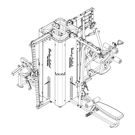
S T E P Be careful to assemble all components in the sequence they are presented. NOTE: Wrench tighten ALL hardware at the end of STEP 1B. Some components may be pre-assembled. Nylon lock nuts will not fully screw onto bolts, they must be wrench tighten to fully go on. - Page 23 S T E P MULTI GYM STATION Above shows Step 1 assembled and completed. LAT PULL STATION LEG PRESS STATION CABLE COLUMN STATION...
- Page 24 S T E P Be careful to assemble all components in the sequence they are presented. NOTE: Wrench tighten ALL hardware at the end of STEP 2B. Some components may be pre-assembled. Nylon lock nuts will not fully screw onto bolts, they must be wrench tighten to fully go on.
- Page 25 S T E P Above shows Step 2 assembled and completed.
- Page 26 S T E P Be careful to assemble all components in the sequence they are presented. NOTE: Finger tighten all hardware in this step. DO NOT wrench tighten until instructed. Some components may be pre-assembled. Nylon lock nuts will not fully screw onto bolts, they must be wrench tightened to fully go on.
- Page 27 S T E P Above shows Step 3 assembled and completed.
- Page 28 S T E P Be careful to assemble all components in the sequence they are presented. NOTE: Wrench tighten ALL hardware at the end of STEP 4B. Some components may be pre-assembled. Nylon lock nuts will not fully screw onto bolts, they must be wrench tighten to fully go on.
- Page 29 S T E P Above shows Step 4 assembled and completed.
- Page 30 S T E P Be careful to assemble all components in the sequence they are presented. NOTE: Wrench tighten ALL hardware at the end of STEP 5J. Some components may be pre-assembled. Nylon lock nuts will not fully screw onto bolts, they must be wrench tighten to fully go on.
- Page 31 S T E P Above shows Step 5 assembled and completed.
- Page 32 S T E P Be careful to assemble all components in the sequence they are presented. NOTE: Wrench tighten ALL hardware at the end of STEP 6M. Some components may be pre-assembled. Nylon lock nuts will not fully screw onto bolts, they must be wrench tighten to fully go on.
- Page 33 S T E P Above shows Step 6 assembled and completed.
- Page 34 S T E P Be careful to assemble all components in the sequence they are presented. NOTE: Wrench tighten ALL hardware at the end of STEP 7B. Some components may be pre-assembled. Nylon lock nuts will not fully screw onto bolts, they must be wrench tighten to fully go on.
- Page 35 S T E P Above shows Step 7 assembled and completed.
- Page 36 S T E P Be careful to assemble all components in the sequence they are presented. NOTE: Wrench tighten ALL hardware at the end of STEP 8E. Some components may be pre-assembled. Nylon lock nuts will not fully screw onto bolts, they must be wrench tighten to fully go on.
- Page 37 S T E P Above shows Step 8 assembled and completed.
- Page 38 S T E P Be careful to assemble all components in the sequence they are presented. NOTE: Wrench tighten ALL hardware at the end of STEP 9G. Some components may be pre-assembled. Nylon lock nuts will not fully screw onto bolts, they must be wrench tighten to fully go on.
- Page 39 S T E P Above shows Step 9 assembled and completed.
- Page 40 S T E P Be careful to assemble all components in the sequence they are presented. NOTE: Wrench tighten ALL hardware at the end of STEP 10E. Some components may be pre-assembled. Nylon lock nuts will not fully screw onto bolts, they must be wrench tighten to fully go on.
- Page 41 S T E P Above shows Step 10 assembled and complet-...
- Page 42 S T E P Be careful to assemble all components in the sequence they are presented. NOTE: Finger tighten all hardware in this step. DO NOT wrench tighten until instructed. Some components may be pre-assembled. Nylon lock nuts will not fully screw onto bolts, they must be wrench tightened to fully go on.
- Page 43 S T E P Above shows Step 11 assembled and complet-...
- Page 44 S T E P Be careful to assemble all components in the sequence they are presented. NOTE: Wrench tighten ALL hardware at the end of STEP 12D. Some components may be pre-assembled. Nylon lock nuts will not fully screw onto bolts, they must be wrench tighten to fully go on.
- Page 45 S T E P Above shows Step 12 assembled and complet-...
- Page 46 S T E P Be careful to assemble all components in the sequence they are presented. NOTE: Wrench tighten ALL hardware at the end of STEP 13L. Some components may be pre-assembled. Nylon lock nuts will not fully screw onto bolts, they must be wrench tighten to fully go on.
- Page 47 S T E P Above shows Step 13 assembled and completed.
- Page 48 S T E P Be careful to assemble all components in the sequence they are presented. NOTE: Wrench tighten ALL hardware at the end of STEP 14H. Some components may be pre-assembled. Nylon lock nuts will not fully screw onto bolts, they must be wrench tighten to fully go on.
- Page 49 S T E P Above shows Step 14 assembled and completed.
- Page 50 S T E P Be careful to assemble all components in the sequence they are presented. NOTE: Wrench tighten ALL hardware at the end of STEP 15B. Some components may be pre-assembled. Nylon lock nuts will not fully screw onto bolts, they must be wrench tighten to fully go on.
- Page 51 S T E P Above shows Step 15 assembled and completed.
- Page 52 S T E P Be careful to assemble all components in the sequence they are presented. NOTE: Wrench tighten ALL hardware at the end of STEP 16E. Some components may be pre-assembled. Nylon lock nuts will not fully screw onto bolts, they must be wrench tighten to fully go on.
- Page 53 S T E P Above shows Step 16 assembled and completed.
- Page 54 S T E P Be careful to assemble all components in the sequence they are presented. NOTE: Wrench tighten ALL hardware at the end of STEP 17K. Some components may be pre-assembled. Nylon lock nuts will not fully screw onto bolts, they must be wrench tighten to fully go on.
- Page 55 S T E P Above shows Step 17 assembled and completed.
- Page 56 S T E P Be careful to assemble all components in the sequence they are presented. NOTE: Wrench tighten ALL hardware at the end of STEP 18D. Some components may be pre-assembled. Nylon lock nuts will not fully screw onto bolts, they must be wrench tighten to fully go on.
- Page 57 S T E P Above shows Step 18 assembled and completed.
- Page 58 S T E P Be careful to assemble all components in the sequence they are presented. NOTE: Wrench tighten ALL hardware at the end of STEP 19E. Some components may be pre-assembled. Nylon lock nuts will not fully screw onto bolts, they must be wrench tighten to fully go on.
- Page 59 S T E P Above shows Step 19 assembled and completed.
- Page 60 S T E P Be careful to assemble all components in the sequence they are presented. NOTE: Wrench tighten ALL hardware at the end of EACH STEP. Some components may be pre-assembled. Nylon lock nuts will not fully screw onto bolts, they must be wrench tighten to fully go on.
- Page 61 S T E P Above shows Step 20 assembled and completed.
- Page 62 S T E P Be careful to assemble all components in the sequence they are presented. NOTE: Wrench tighten ALL hardware at the end of STEP 21G. Some components may be pre-assembled. Nylon lock nuts will not fully screw onto bolts, they must be wrench tighten to fully go on.
- Page 63 S T E P Above shows Step 21 assembled and completed.
- Page 64 S T E P Be careful to assemble all components in the sequence they are presented. NOTE: Wrench tighten ALL hardware at the end of STEP 22B. Some components may be pre-assembled. Nylon lock nuts will not fully screw onto bolts, they must be wrench tighten to fully go on.
- Page 65 S T E P Above shows Step 22 assembled and completed.
- Page 66 S T E P Be careful to assemble all components in the sequence they are presented. NOTE: Wrench tighten ALL hardware at the end of each STEP . Some components may be pre-assembled. Nylon lock nuts will not fully screw onto bolts, they must be wrench tighten to fully go on.
- Page 67 S T E P Above shows Step 23 assembled and completed. MULTI-GYM STATION LEG PRESS STATION LAT PULL STATION CABLE COLUMN STATION...
-
Page 68: Exploded View
S 1 0 0 0 E x p l o d e d V i e w ( 1 ) - Page 69 S 1 0 0 0 E x p l o d e d V i e w ( 2 )
- Page 70 S 1 0 0 0 E x p l o d e d V i e w ( 3 )
- Page 71 S 1 0 0 0 E x p l o d e d V i e w ( 4 )
- Page 72 S 1 0 0 0 E x p l o d e d V i e w ( 5 )
- Page 73 N O T E...
-
Page 74: Contact Page
S1000 PLEASE WRITE YOUR SERIAL NUMBER IN THE BOXES BELOW 017146-��-��-����-���� S/N # 1900 S. Des Plaines Ave. Forest Park, IL 60130 Phone:(708)427-3555 Fax:(708)427-3556 Hours: M-F 8:30 - 5:00 CST www.bodysolid.com Copyright 2009. Body-Solid. All rights reserved. Body-Solid reserves the right to change design and specifications when we feel it will improve the product.
Need help?
Do you have a question about the S1000 and is the answer not in the manual?
Questions and answers