Table of Contents
Advertisement
Quick Links
Advertisement
Table of Contents

Related Manuals for MSI MS-C903


Summary of Contents for MSI MS-C903
- Page 1 MS-C903 Industrial Data Machine User Guide...
-
Page 2: Table Of Contents
Contents Safety Information ......................4 Regulatory Notices ....................... 5 Specifications ....................... 8 System Overview ......................11 ME Overview........................ 17 System Dimensions ....................17 System Dimensions with Wall Mount ..............18 Motherboard Overview ....................19 Motherboard Jumpers ....................20 Getting Started ......................21 Safety Precautions .................... - Page 3 Bios Setup ........................32 Entering Setup ...................... 32 Control Keys ......................33 Getting Help ......................33 Main Menu ......................33 Sub-Menu ......................33 General Help <F1> ....................33 The Menu Bar ......................34 Main ..........................35 Advanced ........................36 Boot..........................44 Security ........................
-
Page 4: Safety Information
Safety Information ∙ The components included in this package are prone to damage from electrostatic discharge (ESD). Please adhere to the following instructions to ensure successful computer assembly. ∙ Ensure that all components are securely connected. Loose connections may cause the computer to not recognize a component or fail to start. -
Page 5: Regulatory Notices
Regulatory Notices CE Conformity Hereby, Micro-Star International CO., LTD declares that this device is in compliance with the essential safety requirements and other relevant provisions set out in the European Directive. FCC-A Radio Frequency Interference Statement This equipment has been tested and found to comply with the limits for a Class A digital device, pursuant to Part 15 of the FCC Rules. - Page 6 Chemical Substances Information In compliance with chemical substances regulations, such as the EU REACH Regulation (Regulation EC No. 1907/2006 of the European Parliament and the Council), MSI provides the information of chemical substances in products at: https://csr.msi.com/global/index Green Product Features ∙...
- Page 7 MSI products. Copyright and Trademarks Notice Copyright © Micro-Star Int’l Co., Ltd. All rights reserved. The MSI logo used is a registered trademark of Micro-Star Int’l Co., Ltd. All other marks and names mentioned may be trademarks of their respective owners. No warranty as to accuracy or completeness is expressed or implied.
-
Page 8: Specifications
Specifications Model MS-C903 • Embedded SKUs (E-Series) - 11th Gen Intel® IoTG Mobile Tiger Lake-UP3 Core™ i7-1185G7E/ i5-1145G7E, QC, 15W up to 28W - 11th Gen Intel® IoTG Mobile Tiger Lake-UP3 Core™ i3-1115G4E, DC, 15W up to 28W Processor • Industrial SKUs (W-Series) - 11th Gen Intel®... - Page 9 Model MS-C903 • 1 x M.2 B Key slot (2242/ 3042) - Supports PCIe x1, SATA 3.0, USB 2.0 signals - Shared with Nano SIM Holder - 4G/ 5G modules supported • 1 x M.2 E Key slot (2230) Expansion Slots - Supports PCIe x1 &...
- Page 10 Model MS-C903 • 19V, 90W Power Adapter - Power Input: 100~240Vac, 50/60Hz, 1.2A Power Solution - Power Output: 19V , 4.74A Dimension 215mm (W) x 155mm (D) x 65mm (H) Weight 2.24kg • Wall mount (STD) Mounting • DIN rail mount (STD) •...
-
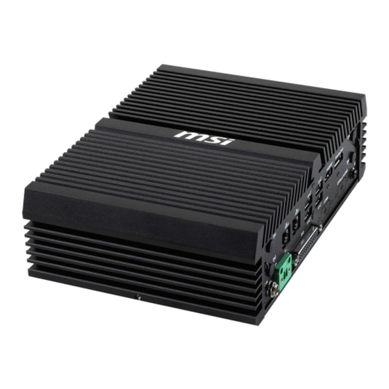
Page 11: System Overview
System Overview Front Panel I/O Rear Panel I/O System Overview... - Page 12 Wi-Fi Antenna Connector (Openings reserved for antennas) These connectors allow you to connect sn external antenna for wireless communication. User may find two on the front side and 4 on the rear side of the system. USB 2.0 Port This connector is provided for USB peripheral devices. (Speed up to 480 Mbps) ⚠...
- Page 13 Extend Switch Connector This connector is provided for remote power button control. Power Button/ LED Press the button to turn the system on or off. LED Status Description ACPI S4/ S5/ Deep S5, Power Off ACPI S3 Blinking ACPI S0 Green Mic-In Jack This connector is provided for microphones.
- Page 14 HDMI™ Connector Supports 4096x2160@30Hz as specified in HDMI™ 1.4. DisplayPort Supports 7680x4320@60Hz as specified in DisplayPort 1.4a. DC Power Jack Power supplied through this jack supplies power to the system. Phoenix DC Power Connector The system is designed with a Phoenix connector that carries DC input. ⚠...
- Page 15 RS232/422/485 Serial Port: COM6 (Optional) The serial port is a 16550A high speed communications port that sends/ receives 16 bytes FIFOs. It supports barcode scanners, barcode printers, bill printers, credit card machine, etc. RS232 SIGNAL DESCRIPTION NDCD Data Carrier Detect NSIN Signal In NSOUT...
- Page 16 RS232/422/485 Serial Port: COM5 / CANBus Port (Optional) The serial port is a 16550A high speed communications port that sends/ receives 16 bytes FIFOs. It supports barcode scanners, barcode printers, bill printers, credit card machine, etc. RS232 SIGNAL DESCRIPTION NDCD Data Carrier Detect NSIN Signal In...
-
Page 17: Me Overview
ME Overview System Dimensions 155.00 164.65 215.00 65.60 ME Overview... -
Page 18: System Dimensions With Wall Mount
System Dimensions with Wall Mount 226.40 214.50 224.90 84.00 94.00 104.00 ME Overview... -
Page 19: Motherboard Overview
Motherboard Overview Rear Panel I/O SYSFAN1 JAUD1 M2_E1 JGPIO1 JCOM1_2 JCOMP1 JCOM3_4 JCOMP2 JPWR1 USIM1 JME_DIS1 DIMM2 JFP1 JUSB1 JUSB2 SATA1 M2_B1 M2_M1 DIMM1 JCOMS1 JPW1 JATX1 Motherboard Overview... -
Page 20: Motherboard Jumpers
Motherboard Jumpers ⚠ Important Avoid adjusting jumpers when the system is on; it will damage the motherboard. JCOMP1 JCOMP2 JME_DIS1 JCOMS1 JATX1 Jumper Name Default Setting Description JME_DIS1 1-2: Normal 2-3: ME Disable JCMOS1 1-2: Normal 2-3: Clear CMOS JATX1 1-2: ATX 2-3: AT JCOMP1... -
Page 21: Getting Started
Getting Started ⚠ Important All information is subject to change without prior notice. ∙ ∙ The system photos are provided for demonstration of system assembly only. The components of your system may differ based on the model you have purchased. Necessary Tools Screwdriver Pliers... -
Page 22: Removing System Cover
Removing System Cover ⚠ Important Before you remove or install any components, make sure the system is not turned on or connected to the AC power. 1. Place the system on a flat and steady surface. Locate and remove the screw on the back side. -
Page 23: Installing Memory Module
Installing Memory Module 1. Align the notch on the memory module with the key on the slot and insert the memory module into the slot at a 45-degree angle. 2. Push the memory module gently downwards until the slot clips click and lock the memory module in place. -
Page 24: Installing M.2 Ssd (M-Key)
Installing M.2 SSD (M-Key) ⚽ Video Demonstration Watch the video to learn how to Install M.2 SSD. M2_M1 1. Loosen the M.2 screw from the motherboard. 2. Insert your M.2 SSD into the M.2 slot at a 30-degree angle. 30° 3. -
Page 25: Installing M.2 Wi-Fi Card (E-Key)
Installing M.2 Wi-Fi Card (E-Key) M2_E1 1. Loosen the M.2 screw from the motherboard. 2. Insert your M.2 Wi-Fi card into the M.2 slot at a 30-degree angle. 3. Secure the M.2 Wi-Fi card in place with the supplied M.2 screw. -
Page 26: Installing M.2 Expansion Card (B-Key)
Installing M.2 Expansion Card (B-Key) M2_B1 1. Loosen the M.2 screw from the motherboard. 2. Insert your M.2 SSD into the M.2 slot at a 30-degree angle. 30° 3. Secure the M.2 SSD in place with the supplied M.2 screw. Installing M.2 Expansion Card (B-Key) -
Page 27: Installing 2.5" Hdd/ Ssd (9.5Mm)
Installing 2.5” HDD/ SSD (9.5mm) 1. Flip over the system cover and locate the HDD/SSD bracket. Remove the protective film to uncover the thermal pad. 2. To install, first insert the HDD/SSD into the bracket with screw holes aligned. Then tighten the screws to fix the HDD/SSD to the bracket. ⚠... - Page 28 3. Align the SATA data & power connector and connect to the HDD/SSD. 4. Connect the SATA signal & power connector to the motherboard to complete the installation. Follow the above procedures in reverse order to replace the HDD/SSD if needed. ∙...
-
Page 29: Wall Mount
Wall Mount 1. Flip over the system and locate the bracket screw holes. 2. Place the brackets and rubber pads along the sides with screw holes aligned. 3. Fasten the screws to fix the brackets. Wall Mount... -
Page 30: Din Rail Mount
Din Rail Mount 1. Attach the DIN rail clips to the wall mount brackets with the hooks aligned. 2. Insert screws through the wall mount brackets into the DIN rail clips and tighten until secure. Din Rail Mount... -
Page 31: Vesa Mount (Optional)
VESA Mount (Optional) 1. Fasten the VESA mount plate to the monitor with the supplied screws. 2. Mount the system onto the VESA mount plate. 3. Tighten the thumbscrew at the bottom of the VESA mount plate to secure the system. -
Page 32: Bios Setup
Bios Setup This chapter provides information on the BIOS Setup program and allows users to configure the system for optimal use. Users may need to run the Setup program when: ∙ An error message appears on the screen at system startup and requests users to run SETUP. -
Page 33: Control Keys
Control Keys ← → Select Screen ↑ ↓ Select Item Enter Select Change Value Exit General Help Previous Values Optimized Defaults Save & Reset* Screenshot capture Scroll help area upwards <K> <M> Scroll help area downwards * When you press F10, a confirmation window appears and it provides the modification information. -
Page 34: The Menu Bar
The Menu Bar ▶ Main Use this menu for basic system configurations, such as time, date, etc. ▶ Advanced Use this menu to set up the items of special enhanced features. ▶ Boot Use this menu to specify the priority of boot devices. ▶... -
Page 35: Main
Main HDD Information ∙ RAID (VMD) Disabled: Display HDD information as plugging in status. ∙ RAID (VMD) Enabled: Display "Not Present" only. ▶ System Date This setting allows you to set the system date. Format: <Day> <Month> <Date> <Year>. ▶ System Time This setting allows you to set the system time. -
Page 36: Advanced
Advanced ▶ Full Screen Logo Display This BIOS feature determines if the BIOS should hide the normal POST messages with the motherboard or system manufacturer’s full-screen logo. [Enabled] BIOS will display the full-screen logo during the boot-up sequence, hiding normal POST messages. [Disabled] BIOS will display the normal POST messages, instead of the full- screen logo. - Page 37 ▶ CPU Configuration ▶ Intel (VMX) Virtualization Technology Virtualization enhanced by Intel Virtualization Technology will allow a platform to run multiple operating systems and applications in independent partitions. With Virtualization, one computer system can function as multiple “virtual” systems. ▶ Active Processor Cores This setting specifies the number of active processor cores.
- Page 38 ▶ Turbo Mode Enables or disables the Turbo Mode. This feature only display when Intel(R) SpeedStep(TM) is enabled. [Enabled] Enables this function to boost CPU performance automatically over specification when system request the highest performance state. [Disabled] Disables this function. ▶...
- Page 39 ▶ Memory Configuration ▶ In-Band ECC Support Enables or disables In-Band ECC(Error-Correcting Code) Support. [Enabled] When enabled this function, a portion(1/32) of memory space will be reserved to store ECC data. [Disabled] Disables this function. » In-Band ECC Error Injection Enables or disables In-Band ECC Error Injection.
- Page 40 ▶ Super IO Configuration ▶ Serial Port 1/ 2/ 3/ 4 This setting enables/disables the specified serial port. » Change Settings This setting is used to change the address & IRQ settings of the specified serial port. » Mode Select Select an operation mode for Serial Port 1/ 2/ 3/ 4.
- Page 41 ▶ H/W Monitor (PC Health Status) These items display the current status of all monitored hardware devices/ components such as voltages, temperatures and all fans’ speeds. ▶ Thermal Shutdown This setting enables/disables the Thermal Shutdown function. It will automatically shuts down when the internal temperature reaches the critical level.
- Page 42 ▶ Smart Fan Configuration ▶ SYSFAN This setting enables/ disables the Smart Fan function. Smart Fan is an excellent feature which will adjust the System fan speed automatically depending on the current system temperature, avoiding the overheating to damage your system. ▶...
- Page 43 ▶ GPIO Group Configuration ▶ GPO0 ~ GPO7 These settings control the operation mode of the specified GPIO. Advanced...
-
Page 44: Boot
Boot ▶ Boot Option Priorities This setting allows users to set the sequence of boot devices where BIOS attempts to load the disk operating system. Boot... -
Page 45: Security
Security ▶ Administrator Password Administrator Password controls access to the BIOS Setup utility. ▶ User Password User Password controls access to the system at boot and to the BIOS Setup utility. ▶ Intel BIOS Guard Support Intel BIOS Guard Support ensures that updates to system BIOS flash are secure. Security... - Page 46 ▶ PCH-FW Configuration Firmware Information These settings show the ME Firmware Version System Integrity Value firmware information of the ME Firmware Mode ME Firmware Status 1 Intel ME (Management Engine). ME Firmware SKU ME Firmware Status 2 ▶ ME State This setting specifies the Intel Management Engine state.
- Page 47 ▶ Firmware Update Configuration » ME FW Image Re-Flash This setting enables/ disables the ME FW (Firmware) image re-flash. » FW Update This setting enables/ disables the FW (Firmware) update. ▶ PTT Configuration Intel Platform Trust Technology (PTT) is a platform functionality for credential storage and key management used by Microsoft Windows.
- Page 48 » HECI Message Check Disable This setting disables message check for BIOS boot path when sending messages. » MBP HOB Skip Setting this option will skip MBP HOB. » HECI2 Interface Communication This setting Adds/ Removes HECI2 device from PCI space. »...
- Page 49 ▶ AMT Configuration Intel Active Management Technology (AMT) is hardware-based technology for remotely managing and securing PCs out-of-band. ▶ USB Provisioning of AMT Enables or disable USB Provisioning of AMT. ▶ CIRA Configuration » Activate Remote Assistance Process Setting this option enables will trigger CIRA boot. »...
- Page 50 ▶ ASF Configuration » PET Progress Setting this option enables/ disables to receive PET Events. » WatchDog This setting enables/ disables the watchdog timer. » OS Timer This item displays OS Timer. » BIOS Timer This item displays BIOS Timer. »...
- Page 51 ▶ OEM Flag Setting » MEBx hotkey Pressed This setting enables/ disables the management Engine BIOS Extension(MEBx) hotkey Pressed. » MEBx Selection Screen This setting enables/ disables the MEBx Selection Screen. » Hide Unconfigure ME Confirmation Prompt This setting enables/ disables the Hide Unconfigure ME Confirmation Prompt. »...
- Page 52 ▶ Trusted Computing ▶ Security Device Support This setting enables/disables BIOS support for security device. When set to [Disable], the OS will not show security device. TCG EFI protocol and INT1A interface will not be available. ▶ SHA256 PCR Bank These settings enable/disable the SHA-1 PCR Bank and SHA256 PCR Bank.
- Page 53 ▶ Serial Port Console Redirection ▶ Console Redirection Console Redirection operates in host systems that do not have a monitor and keyboard attached. This setting enables/disables the operation of console redirection. When set to [Enabled], BIOS redirects and sends all contents that should be displayed on the screen to the serial COM port for display on the terminal screen.
- Page 54 ▶ Console Redirection Settings (COM1) » Terminal Type To operate the system’s console redirection, you need a terminal supporting ANSI terminal protocol and a RS-232 null modem cable connected between the host system and terminal(s). You can select emulation for the terminal from this setting. [ANSI] Extended ASCII character set.
- Page 55 ▶ Console Redirection Settings (Out-of-Band Management) » Out-of-Band Mgmt Port This setting specifies the Out-of-Band Management Port. Terminal Type EMS (Windows Emergency Management Service) » You can select the type of terminal device for console redirection from this setting. [VT-UTF8] is the preferred terminal type for the out-of-band management. The next best choice is [VT100+] and then [VT100].
-
Page 56: Chipset
Chipset ▶ DVMT Total Gfx Mem This setting specifies the memory size for DVMT. Chipset... -
Page 57: Power
Power ▶ Restore AC Power Loss This setting specifies whether your system will reboot after a power failure or interrupt occurs. Available settings are: [Power Off] Leaves the computer in the power off state. [Power On] Leaves the computer in the power on state. [Last State] Restores the system to the previous status before power failure or interrupt occurred. -
Page 58: Save & Exit
Save & Exit ▶ Save Changes and Reset Save changes to CMOS and reset the system. ▶ Discard Changes and Exit Abandon all changes and exit the Setup Utility. ▶ Discard Changes Abandon all changes. ▶ Load Optimized Defaults Use this menu to load the default values set by the motherboard manufacturer specifically for optimal performance of the motherboard. -
Page 59: Gpio Wdt Bkl Smbus Programming
GPIO WDT BKL SMBus Programming This chapter provides WDT (Watch Dog Timer), GPIO (General Purpose Input/ Output) LVDS Backlight and SMBus Access programming guide. Abstract In this section, code examples based on C programming language provided for customer interest. Inportb, Outportb, Inportl and Outportl are basic functions used for access IO ports and defined as following. -
Page 60: General Purpose Io
General Purpose IO 1. General Purposed IO – GPIO/DIO The GPIO port configuration addresses are listed in the following table: Name IO Port IO address Name IO Port IO address N_GPI0 0x22 Bit 4 N_GPO0 0x11 Bit 4 N_GPI1 N_GPO1 0x22 Bit 5 0x11... - Page 61 Example: Set N_GPO1 output “low” val = SMBus_ReadByte (0x6E, 0x11); // Read value from N_GPO1 port through SMBus.. val = val & (~(1<<5)); // Set N_GPO1 address (bit 5) to 0 (output “low”). SMBus_WriteByte (0x6E, 0x11, val); // Write back to N_GPO1 port through SMBus. 1.2 Read input value from GPI: 1.
-
Page 62: Watchdog Timer
Watchdog Timer 2. Watchdog Timer – WDT The base address (WDT_BASE) of WDT configuration registers is 0xA10. 2.1 Set WDT Time Unit val = Inportb (WDT_BASE + 0x05); // Read current WDT setting val = val | 0x08; // minute mode. val = val & 0xF7 if second mode Outportb (WDT_BASE + 0x05, val);... - Page 63 2.4 Disable WDT val = Inportb (WDT_BASE + 0x05); // Read current WDT setting val = val & 0xDF; // Disable WDT by set WD_EN (bit 5) to 0. Outportb (WDT_BASE + 0x05, val); // Write back WDT setting. 2.5 Check WDT Reset Flag If the system has been reset by WDT function, this flag will set to 1.
-
Page 64: Smbus Access
SMBus Access 4. SMBus Access The base address of SMBus must know before access. The relevant bus and device information are as following. #define IO_SC 0xCF8 #define IO_DA 0xCFC #define PCIBASEADDRESS 0x80000000 #define PCI_BUS_NUM #define PCI_DEV_NUM #define PCI_FUN_NUM 4.1 Get SMBus Base Address int SMBUS_BASE;... - Page 65 Outportb (LOWORD ( ) + 0x02, 0x48); //out Base + 02, 48H SMBUS_BASE mdelay (20); //delay 20ms to let data ready while ((Inportl ( ) & 0x01) != 0); //wait SMBus ready SMBUS_BASE _DATA = Inportb (LOWORD ( ) + 0x05); //input Base + 05 SMBUS_BASE 4.3 SMBus_WriteByte (char DEVID, char offset, char DATA)
Need help?
Do you have a question about the MS-C903 and is the answer not in the manual?
Questions and answers