Table of Contents
Advertisement
Quick Links
Advertisement
Table of Contents

Related Manuals for MSI MS-9A66


Summary of Contents for MSI MS-9A66
- Page 1 MS-9A66 Industrial Data Machine...
-
Page 2: Revision History
Alterna- tively, please try the following help resources for further guidance. Visit the MSI website for technical guide, BIOS updates, driver updates and other information, or contact our technical staff via http://www.msi.com/support/... -
Page 3: Safety Instructions
MS-9A66 Safety Instructions ■ Always read the safety instructions carefully. ■ Keep this User’s Manual for future reference. ■ Keep this equipment away from humidity. ■ Lay this equipment on a reliable flat surface before setting it up. ■ The openings on the enclosure are for air convection hence protects the equipment from overheating. -
Page 4: Chemical Substances Information
Chemical Substances Information In compliance with chemical substances regulations, such as the EU REACH Regulation (Regulation EC No. 1907/2006 of the European Parliament and the Council), MSI provides the information of chemical substances in products at: http://www.msi.com/html/popup/csr/evmtprtt_pcm.html Battery Information European Union: Batteries, battery packs, and accumulators should not be disposed of as unsorted household waste. -
Page 5: Ce Conformity
MS-9A66 CE Conformity Hereby, Micro-Star International CO., LTD declares that this de- vice is in compliance with the essential safety requirements and other relevant provisions set out in the European Directive. FCC-A Radio Frequency Interference Statement This equipment has been tested and found to comply with the limits for a Class A digital device, pursuant to Part 15 of the FCC Rules. -
Page 6: Table Of Contents
Block Diagram ..................1-11 Motherboard Jumpers ................1-12 ME Overview ....................1-14 2. Getting Started ................2-1 Installing System Components ..............2-2 3. BIOS Setup ...................3-1 Entering Setup ...................3-2 MS-9A66 (Q87) ..................3-4 The Menu Bar ....................3-4 Main ......................3-5 Advanced ....................3-6 Boot ......................3-12 Security ....................3-13 Chipset .....................3-18 Power .......................3-19... - Page 7 MS-9A66 Power .......................3-37 Save & Exit ....................3-39 4. MSI HIDAC Utility .................4-1 Activating the Utility ..................4-2 GPIO (DIO) ....................4-2 Watchdog ....................4-3 System Info....................4-3 HW Monitor ....................4-4 Alarm Settings ....................4-4 Alarm Logs ....................4-5 Appendix WDT, GPIO, DIO .............. A-1 WDT Sample Code ................... A-2 GPIO Sample Code ..................
-
Page 9: Overview
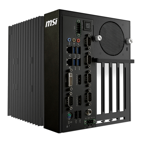
Thank you for choosing the MS-9A66, a high-performance automation computer from MSI. A highly integrated, rugged system that features versatile I/O capability and PCIe expansion slots, the MS-9A66 is perfect for a wide variety of industrial applications, including machine automation, video surveillance, facility environment monitoring, intelligent transportation, etc. -
Page 10: System Overview
Overview System Overview System I/O & Controls Internal View... - Page 11 MS-9A66 System Power Button Press the system power button to turn the system on or off. Digital I/O Connector This Digital I/O connector can be used in various industrial applications like programmable logic devices and embedded, custom applications that make...
- Page 12 Overview RS-232/422/485 Serial Port: COM1 (0V/5V/12V) The serial port is a 16550A high speed communications port that sends/ receives 16 bytes FIFOs. It supports barcode scanners, barcode printers, bill printers, credit card machine, etc. RS-232 SIGNAL DESCRIPTION NDCD Data Carrier Detect NSIN Signal In NSOUT...
- Page 13 MS-9A66 RS-232/422/485 Serial Port: COM2 (0V) The serial port is a 16550A high speed communications port that sends/ receives 16 bytes FIFOs. It supports barcode scanners, barcode printers, bill printers, credit card machine, etc. RS-232 SIGNAL DESCRIPTION NDCD Data Carrier Detect...
- Page 14 Overview RS-232 Serial Port: COM3, COM4, COM5 (0V) The serial port is a 16550A high speed communications port that sends/ receives 16 bytes FIFOs. It supports barcode scanners, barcode printers, bill printers, credit card machine, etc. RS-232 SIGNAL DESCRIPTION NDCD Data Carrier Detect NSIN Signal In...
- Page 15 MS-9A66 Audio Jack ■ Line-In (Blue) - for external CD player or other audio devices ■ Line-Out (Green) - for speakers or headphones ■ Mic-In (Pink) - for microphones HDD Bracket This bracket is provided for hard disk drives. Memory Slot These slots are intended for memory modules.
-
Page 16: System Specifications
Overview System Specifications Processor ■ Intel 4th generation Core i7/ i5/ i3/ Celeron/ Pentium processor (LGA1150) Chipset ■ Intel Q87/C226 chipset Memory ■ 2 * Non-ECC, unbuffered DDR3 1066/1333/1600 MHz SO-DIMM slots ■ Support Dual-Channel mode ■ Up to 16 GB ■... - Page 17 MS-9A66 Expansion Slot ■ 1 * PCIe x16 slot / 2 * PCIe x8 slots - Maximum card length: 197mm - Maximum card height (with optional bracket): 118mm - Minimum card height (with optional bracket): 90mm ■ 3 * PCI slots / 2 * PCI slots - With 1 HDD installed: »...
- Page 18 ■ Windows 8.1 64 Bit ■ Windows 10 64 Bit Hardware Options ■ Optional fan module covers available to enhance heat dissipation from installed PCI/PCIe cards SKU Comparison SKUs MS-9A66 (Q87) MS-9A66 (C226) Features Motherboard MS-98F2 (Q87) MS-98F2 (C226) MS-9989...
-
Page 19: Block Diagram
MS-9A66 Block Diagram MS-9A66 (Q87) MS-9A66 (C226) 1-11... -
Page 20: Motherboard Jumpers
Overview Motherboard Jumpers JCOMP1 JCMOS1 JME1 JAT1 1-12... - Page 21 MS-9A66 Clear CMOS Jumper: JCMOS1 Normal Clear CMOS (Default) AT/ATX Select Jumper: JAT1 ATX (Default) ME Jumper: JME1 Normal ME disable (Default) Serial Port Power Jumper: JCOMP1 +5V (Default) +12V 1-13...
-
Page 22: Me Overview
Overview ME Overview System Dimensions without Wall Mount 1-14... - Page 23 MS-9A66 System Dimensions with Wall Mount 1-15...
- Page 24 Overview 1-16...
- Page 25 MS-9A66 MS-9A66 (Q87) PCIe Card Dimensions 1-17...
- Page 26 Overview MS-9A66 (Q87) PCI Card Dimensions 1-18...
- Page 27 MS-9A66 1-19...
- Page 28 Overview MS-9A66 (C226) PCIe Card Dimensions 1-20...
- Page 29 MS-9A66 MS-9A66 (C226) PCI Card Dimensions 1-21...
- Page 30 Overview 1-22...
- Page 31 MS-9A66 Mounting Brackets 1-23...
- Page 32 Overview ■ Mounting Bracket Screws ■ Installation 1 1-24...
- Page 33 MS-9A66 ■ Installation 2 1-25...
-
Page 35: Getting Started
Getting Started This chapter provides you with the information on hardware setup procedures. While connecting peripheral devices, be careful in holding the devices and use a grounded wrist strap to avoid static electricity. 1-2-1... -
Page 36: Installing System Components
Getting Started Installing System Components Important Turn off the system and unplug the power cord before installing or replacing system components. h Top Cover 1. Locate the thumbscrews on the front panel of the system. 2. Loosen the thumbscrews to release the top cover. - Page 37 MS-9A66 3. Push the top cover gently forward. 4. Remove the top cover from the system.
- Page 38 Getting Started h Memory 1. Locate the memory slot. 2. Align the notch on the memory with the key on the slot and insert the memory into the slot at a 45-degree angle. 3. Push the memory gently downwards until the slot clips click and lock the memory in place.
- Page 39 MS-9A66 h 1st Hard Disk Drive 1. Locate the HDD mounting kit. 2. Unscrew the HDD mounting kit to free it up for removal. 3. Gently remove the mounting kit from the system.
- Page 40 Getting Started 4. Identify the components necessary for HDD installation. Retaining Lip HDD Mounting Thermal HDD Tray Bracket 5. Fit the HDD into the tray. Be sure to put the HDD in the correct orientation. 6. Peel off the transparent protective film of the thermal pad.
- Page 41 MS-9A66 7. Place the thermal pad onto the HDD. Check the following picture for the exact location of the thermal pad. Once the thermal pad is secured, peel off the yellow protective film. 8. Fit the HDD into the mounting bracket.
- Page 42 Getting Started 10. To avoid clutter, tidy up the retaining lip behind the HDD. 11. Connect the SATA data cable to the onboard SATA connector. 12. Connect the SATA data cable to the HDD.
- Page 43 MS-9A66 13. Connect the SATA power cable to the onboard SATA power connector. 14. Connect the SATA power cable to the HDD. 15. Route the cables through the cable routing clip.
- Page 44 Getting Started h 2nd Hard Disk Drive (Optional) 1. Identify the components necessary for HDD installation. Retaining Lip HDD Mounting Thermal HDD Tray Bracket 2. Fit the HDD into the tray. Be sure to put the HDD in the correct orientation.
- Page 45 MS-9A66 4. Place the thermal pad onto the HDD. Check the following picture for the exact location of the thermal pad. Once the thermal pad is secured, peel off the yellow protective film. 5. Fit the HDD into the mounting bracket.
- Page 46 Getting Started 7. Fasten the HDD set to the system with screws. 8. To avoid clutter, tidy up the retaining lip behind the HDD. 9. Connect the SATA data cable to the onboard SATA connector. 2-12...
- Page 47 MS-9A66 10. Connect the SATA data and power cables to the HDD. 11. Tidy up the cables by routing them through the cable routing clip. 2-13...
- Page 48 Getting Started h USB DOM 1. Locate the onboard USB port. 2. Connect the USB DOM directly to the port. 2-14...
- Page 49 MS-9A66 h CFast Card 1. Locate the onboard CFast socket. 2. Insert the CFast card into the socket. 3. Push the card gently downwards to secure it in place. 2-15...
- Page 50 Getting Started h PCIe Expansion Card 1. Locate the PCIe slot and remove the card bracket from the chassis. 2. Check the card’s keyed components for correct alignment with the slot and lower the card into the slot. Push the card gently downwards to secure it in place.
- Page 51 MS-9A66 3. Screw the card to the chassis to fix it in place. 4. (Optional) A protective bracket is provided to cut down on system vibrations that may damage the card. First fix the sponge to the bracket. SCREW 6#-32-4L 5.
- Page 52 Getting Started h Fan Module (Optional) 1. Identify the components necessary for fan module installation. 2. Mount the fan module over the air ventilation holes on the system top cover. 3. Put the fan bracket atop the fan and screw it to the fan in diagonal sequence.
- Page 53 MS-9A66 4. Connect the fan power connector to the motherboard. 2-19...
- Page 54 Getting Started h Mounting Brackets (Optional) 1. Identify the components necessary for mounting bracket installation. 2. Screw the brackets to the system. Two types of installation are available. Pick the one that best suits your need. 2-20...
- Page 55 MS-9A66 h Connecting Power (Optional) With a redundant power supply solution, users may feed the power through the DC power jack and/or through the 9V~36V Phoenix DC connector. 1. Locate the DC power connector on the system panel. 2. Connect a DC receptacle connector to it.
- Page 56 Getting Started h Connecting DIO (Optional) 1. Locate the DIO connector on the system panel. 2. Connect a DIO switch connector to 2-22...
-
Page 57: Bios Setup
BIOS Setup This chapter provides information on the BIOS Setup program and allows users to configure the system for optimal use. Users may need to run the Setup program when: ■ An error message appears on the screen at system startup and re- quests users to run SETUP. -
Page 58: Entering Setup
BIOS Setup Entering Setup Power on the computer and the system will start POST (Power On Self Test) process. When the message below appears on the screen, press <DEL> or <F2> key to enter Setup. Press <DEL> or <F2> to enter SETUP If the message disappears before you respond and you still wish to enter Setup, restart the system by turning it OFF and On or pressing the RESET button. - Page 59 MS-9A66 Control Keys ← → Select Screen ↑ ↓ Select Item Enter Select Change Option General Help Previous Values Optimized Defaults Save & Exit Exit Getting Help After entering the Setup menu, the first menu you will see is the Main Menu.
-
Page 60: Ms-9A66 (Q87)
BIOS Setup MS-9A66 (Q87) The Menu Bar ▶ Main Use this menu for basic system configurations, such as time, date, etc. ▶ Advanced Use this menu to set up the items of special enhanced features. ▶ Boot Use this menu to specify the priority of boot devices. -
Page 61: Main
MS-9A66 Main ▶ System Date This setting allows you to set the system date. The date format is <Day>, <Month> <Date> <Year>. ▶ System Time This setting allows you to set the system time. The time format is <Hour> <Min- ute>... -
Page 62: Advanced
BIOS Setup Advanced ▶ Full Screen Logo Display This BIOS feature determines if the BIOS should hide the normal POST mes- sages with the motherboard or system manufacturer’s full-screen logo. When it is enabled, the BIOS will display the full-screen logo during the boot-up sequence, hiding normal POST messages. - Page 63 MS-9A66 ▶ PCI/PCIE Device Configuration ▶ EHCI1, EHCI2 This setting disables/enables the USB EHCI controller. The Enhanced Host Controller Interface (EHCI) specification describes the register-level interface for a Host Controller for the Universal Serial Bus (USB) Revision 2.0. ▶ XHCI Mode This setting disables/enables the USB XHCI controller.
- Page 64 BIOS Setup ▶ CPU Configuration ▶ Hyper-Threading The processor uses Hyper-Threading technology to increase transaction rates and reduces end-user response times. The technology treats the two cores inside the processor as two logical processors that can execute instructions simultaneously. In this way, the system performance is highly improved. If you disable the function, the processor will use only one core to execute the instructions.
- Page 65 MS-9A66 ▶ Super IO Configuration ▶ Serial Port 1/ 2/ 3/ 4/ 5 This setting enables/disables the specified serial port. ▶ Change Settings This setting is used to change the address & IRQ settings of the specified serial port. ▶ Mode Select Select an operation mode for the specified serial port.
- Page 66 BIOS Setup ▶ H/W Monitor These items display the current status of all monitored hardware devices/ components such as voltages, temperatures and all fans’ speeds. ▶ Smart Fan Configuration ▶ Smart SYSFAN1 Target These settings enable/disable the Smart Fan function. Smart Fan is an excellent feature which will adjust the CPU/system fan speed automatically depending on the current CPU/system temperature, avoiding the overheating to damage your system.
- Page 67 MS-9A66 ▶ GPIO Group Configuration ▶ GPO0 ~ GPO3 Data These settings control the operation mode of the specified GPIO. 3-11...
-
Page 68: Boot
BIOS Setup Boot ▶ Boot Option Priorities This setting allows users to set the sequence of boot devices where BIOS at- tempts to load the disk operating system. ▶ Hard Drive BBS Priorities This setting allows users to set the priority of the specified devices. First press <Enter>... -
Page 69: Security
MS-9A66 Security ▶ Administrator Password Administrator Password controls access to the BIOS Setup utility. ▶ User Password User Password controls access to the system at boot and to the BIOS Setup utility. ▶ Chassis Intrusion The field enables or disables the feature of recording the chassis intrusion status and issuing a warning message if the chassis is once opened. - Page 70 BIOS Setup ▶ Trusted Computing ▶ Security Device Support This setting enables/disables BIOS support for security device. When set to [Disable], the OS will not show security device. TCG EFI protocol and INT1A interface will not be available. ▶ PCH-FW Configuration ▶...
- Page 71 MS-9A66 ▶ MDES BIOS Status Code This setting enables/disables the MDES BIOS status code. ▶ Firmware Update Configuration ▶ ME FW Image Re-Flash This setting enables/disables the ME FW image reflash. ▶ Intel(R) Anti-Theft Technology Configuration Intel Anti-Theft Technology is hardware-based technology that can lock a lost or stolen system so that personal confidential information is protected and inacces- sible by unauthorized users.
- Page 72 BIOS Setup ▶ AMT Configuration Intel Active Management Technology (AMT) is hardware-based technology for remotely managing and securing PCs out-of-band. ▶ Serial Port Console Redirection ▶ Console Redirection Console Redirection operates in host systems that do not have a monitor and keyboard attached.
- Page 73 MS-9A66 ▶ Console Redirection Settings ▶ Terminal Type To operate the system’s console redirection, you need a terminal supporting ANSI terminal protocol and a RS-232 null modem cable connected between the host system and terminal(s). This setting specifies the type of terminal device for console redirection.
-
Page 74: Chipset
BIOS Setup Chipset ▶ VT-d Intel Virtualization Technology for Directed I/O (Intel VT-d) provides the capability to ensure improved isolation of I/O resources for greater reliability, security, and availability. ▶ Primary Display This setting specifies which is your primary graphics adapter. ▶... -
Page 75: Power
MS-9A66 Power ▶ Restore AC Power Loss This setting specifies whether your system will reboot after a power failure or interrupt occurs. Available settings are: [Power Off] Leaves the computer in the power off state. [Power On] Leaves the computer in the power on state. - Page 76 BIOS Setup ** Advanced Resume Events Control ** ▶ USB from S3/S4 The item allows the activity of the USB device to wake up the system from S3/S4 sleep state. ▶ OnChip GbE from S5 This field specifies whether the system will be awakened from power saving modes when activity or input signal of onchip LAN is detected.
-
Page 77: Save & Exit
MS-9A66 Save & Exit ▶ Save Changes and Reset Save changes to CMOS and reset the system. ▶ Discard Changes and Exit Abandon all changes and exit the Setup Utility. ▶ Discard Changes Abandon all changes. ▶ Load Optimized Defaults Use this menu to load the default values set by the motherboard manufacturer specifically for optimal performance of the motherboard. -
Page 78: Ms-9A66 (C226)
BIOS Setup MS-9A66 (C226) The Menu Bar ▶ Main Use this menu for basic system configurations, such as time, date, etc. ▶ Advanced Use this menu to set up the items of special enhanced features. ▶ Boot Use this menu to specify the priority of boot devices. -
Page 79: Main
MS-9A66 Main ▶ System Date This setting allows you to set the system date. The date format is <Day>, <Month> <Date> <Year>. ▶ System Time This setting allows you to set the system time. The time format is <Hour> <Min- ute>... -
Page 80: Advanced
BIOS Setup Advanced ▶ Full Screen Logo Display This BIOS feature determines if the BIOS should hide the normal POST messag- es with the motherboard or system manufacturer’s full-screen logo. When it is enabled, the BIOS will display the full-screen logo during the boot-up sequence, hiding normal POST messages. - Page 81 MS-9A66 ▶ PCI/PCIE Device Configuration ▶ EHCI1, EHCI2 This setting disables/enables the USB EHCI controller. The Enhanced Host Controller Interface (EHCI) specification describes the register-level interface for a Host Controller for the Universal Serial Bus (USB) Revision 2.0. ▶ XHCI Mode This setting disables/enables the USB XHCI controller.
- Page 82 BIOS Setup ▶ CPU Configuration ▶ Hyper-Threading The processor uses Hyper-Threading technology to increase transaction rates and reduces end-user response times. The technology treats the two cores inside the processor as two logical processors that can execute instructions simultaneously. In this way, the system performance is highly improved. If you disable the function, the processor will use only one core to execute the instructions.
- Page 83 MS-9A66 ▶ Super IO Configuration ▶ Serial Port 1/ 2/ 3/ 4/ 5 This setting enables/disables the specified serial port. ▶ Change Settings This setting is used to change the address & IRQ settings of the specified serial port. ▶ Mode Select Select an operation mode for the specified serial port.
- Page 84 BIOS Setup ▶ H/W Monitor These items display the current status of all monitored hardware devices/ components such as voltages, temperatures and all fans’ speeds. ▶ Thermal Shutdown This setting enables/disables the thermal shutdown function for system thermal protection. ▶ Smart Fan Configuration ▶...
- Page 85 MS-9A66 ▶ GPIO Group Configuration ▶ GPO0 ~ GPO3 Data These settings control the operation mode of the specified GPIO. 3-29...
-
Page 86: Boot
BIOS Setup Boot ▶ Boot Option Priorities This setting allows users to set the sequence of boot devices where BIOS at- tempts to load the disk operating system. ▶ Hard Drive BBS Priorities This setting allows users to set the priority of the specified devices. First press <Enter>... -
Page 87: Security
MS-9A66 Security ▶ Administrator Password Administrator Password controls access to the BIOS Setup utility. ▶ User Password User Password controls access to the system at boot and to the BIOS Setup utility. ▶ Chassis Intrusion The field enables or disables the feature of recording the chassis intrusion status and issuing a warning message if the chassis is once opened. - Page 88 BIOS Setup ▶ Trusted Computing ▶ Security Device Support This setting enables/disables BIOS support for security device. When set to [Disable], the OS will not show security device. TCG EFI protocol and INT1A interface will not be available. ▶ PCH-FW Configuration ▶...
- Page 89 MS-9A66 ▶ MDES BIOS Status Code This setting enables/disables the MDES BIOS status code. ▶ Firmware Update Configuration ▶ ME FW Image Re-Flash This setting enables/disables the ME FW image reflash. ▶ AMT Configuration Intel Active Management Technology (AMT) is hardware-based technology for remotely managing and securing PCs out-of-band.
- Page 90 BIOS Setup ▶ Serial Port Console Redirection ▶ Console Redirection Console Redirection operates in host systems that do not have a monitor and keyboard attached. This setting enables/disables the operation of console redirection. When set to [Enabled], BIOS redirects and sends all contents that should be displayed on the screen to the serial COM port for display on the terminal screen.
- Page 91 MS-9A66 ▶ Terminal Type To operate the system’s console redirection, you need a terminal supporting ANSI terminal protocol and a RS-232 null modem cable connected between the host system and terminal(s). This setting specifies the type of terminal device for console redirection.
-
Page 92: Chipset
BIOS Setup Chipset ▶ VT-d Intel Virtualization Technology for Directed I/O (Intel VT-d) provides the capability to ensure improved isolation of I/O resources for greater reliability, security, and availability. ▶ Primary Display This setting specifies which is your primary graphics adapter. ▶... -
Page 93: Power
MS-9A66 Power ▶ Restore AC Power Loss This setting specifies whether your system will reboot after a power failure or interrupt occurs. Available settings are: [Power Off] Leaves the computer in the power off state. [Power On] Leaves the computer in the power on state. - Page 94 BIOS Setup ** Advanced Resume Events Control ** ▶ USB from S3/S4 The item allows the activity of the USB device to wake up the system from S3/ S4 sleep state. ▶ OnChip GbE This field specifies whether the system will be awakened from power saving modes when activity or input signal of onchip LAN is detected.
-
Page 95: Save & Exit
MS-9A66 Save & Exit ▶ Save Changes and Reset Save changes to CMOS and reset the system. ▶ Discard Changes and Exit Abandon all changes and exit the Setup Utility. ▶ Discard Changes Abandon all changes. ▶ Load Optimized Defaults Use this menu to load the default values set by the motherboard manufacturer specifically for optimal performance of the motherboard. -
Page 97: Msi Hidac Utility
MSI HIDAC Utility This section introduces the MSI HIDAC utility for overall system monitor and control. 2-4-1... -
Page 98: Activating The Utility
MSI HIDAC Utility Activating the Utility Select [MSI HIDAC Utility] on Desktop to activate the utility. This MSI HIDAC Utility provides information on: ■ GPIO (DIO) ■ Watchdog Timer ■ System Information ■ Hardware Monitor ■ Alarm Settings for Hardware Monitor ■... -
Page 99: Watchdog
MS-9A66 Watchdog Features: ■ Initial Timer configurable through WDT Settings ■ WDT Tools available for automatically activating Watchdog Timer at system boot and automatically resetting timer after a preset time interval ■ Real-time display of Watchdog Timer status System Info. -
Page 100: Hw Monitor
MSI HIDAC Utility HW Monitor Features: ■ Real-time display of Hardware Monitor status including CPU/system temperatures, fan speeds and CPU/system voltage info Alarm Settings Features: ■ Custom settings of a tolerance range for the alarm triggers ■ Automatic alarm logs of monitored hardware items when the alarm trigger... -
Page 101: Alarm Logs
MS-9A66 Alarm Logs Features: ■ Real-time display of Hardware Monitor alarm logs ■ Alarm logs sortable by button (Information, Warning or Error) ■ Alarm logs clearable through Clear Logs... -
Page 103: Appendix Wdt, Gpio, Dio
Appendix WDT, GPIO, DIO This appendix provides information on WDT (Watch Dog Timer), GPIO (General Purpose Input/Output) and DIO (Digital Input/Output). 2-A-1... -
Page 104: Wdt Sample Code
WDT, GPIO, DIO WDT Sample Code SIO_INDEX_Port equ 04Eh SIO_DATA_Port equ 04Fh SIO_UnLock_Value equ 087h SIO_Lock_Value equ 0AAh WatchDog_LDN equ 007h WDT_UNIT equ 60h ;60h=second, 68h=minute, 40h=Disabled Watchdog timer WDT_Timer equ 30 ;ex. 30 seconds Sample code: ;Enable config mode dx, SIO_INDEX_Port al, SIO_UnLock_Value dx, al... -
Page 105: Gpio Sample Code
MS-9A66 GPIO Sample Code GPI 0 ~ GPI 3 GPI 0 GPI 1 GPI 2 GPI 3 IO Address SIO GPIO Register Sample code GPO 0 ~ GPO 3 GPO 0 GPO 1 GPO 2 GPO 3 IO Address... - Page 106 WDT, GPIO, DIO dx, SIO_INDEX_Port al, SIO_GPIO_Status dx, al dx, SIO_DATA_Port al, dx ;al bit0 = GPI 0 status ; Exit SIO dx, SIO_INDEX_Port al, SIO_Lock_Value dx, al #2 : Set GPO 0 to high ; Enable config mode dx, SIO_INDEX_Port al, SIO_UnLock_Value dx, al short $+2...
-
Page 107: Digital I/O Connector
MS-9A66 Digital I/O Connector The MS-9A66 features an onboard isolated digital I/O circuit and supports the following features: ■ 4-CH Isolated DI - Logic high: 5 to 24 V - Logic low: 0 to 1.5 V - Input resistance: 8.2K @ 0.75W... - Page 108 WDT, GPIO, DIO Isolated Digital Input Circuits Input accepts voltages up to 24V, with input resistors of 8.2 kΩ, with connections between outside signals as shown. Isolated Digital Output Circuits Each isolation digital output channel adopts a MOSFET transistor, capable of driving peak current up to 250mA (sustained current up to 100 mA) with voltage ranges from 5V to 35V.
Need help?
Do you have a question about the MS-9A66 and is the answer not in the manual?
Questions and answers