Table of Contents
Advertisement
Quick Links
Advertisement
Table of Contents

Related Manuals for MSI MS-C910


Summary of Contents for MSI MS-C910
- Page 1 MS-C910 Industrial Data Machine User Guide...
-
Page 2: Table Of Contents
Contents Safety Information ......................4 Regulatory Notices ....................... 5 Specifications ........................ 8 SKU Features Comparison ..................11 System Overview ......................12 System I/O & Controls ................... 13 System Internal View ..................... 17 ME Overview........................ 18 System Dimensions ....................18 PCIe and PCI Card Dimensions ................26 Motherboard Jumpers .................... - Page 3 Mini-PCIe Slot ( for SKU2 Only) ................. 38 Installing Mini-PCIe Card ..................38 2.5” SSD/HDD Brackets (for SKU1~3) ..............39 Installing 2.5” HDD/ SSD (7mm) ................39 PCIe Expansion Card ....................43 Installing PCIe Expansion Card ................43 Power Connector ......................45 Connecting DC Receptacle Connector ..............
-
Page 4: Safety Information
Safety Information ∙ The components included in this package are prone to damage from electrostatic discharge (ESD). Please adhere to the following instructions to ensure successful computer assembly. ∙ Ensure that all components are securely connected. Loose connections may cause the computer to not recognize a component or fail to start. -
Page 5: Regulatory Notices
Regulatory Notices CE Conformity Hereby, Micro-Star International CO., LTD declares that this device is in compliance with the essential safety requirements and other relevant provisions set out in the European Directive. FCC-A Radio Frequency Interference Statement This equipment has been tested and found to comply with the limits for a Class A digital device, pursuant to Part 15 of the FCC Rules. - Page 6 Chemical Substances Information In compliance with chemical substances regulations, such as the EU REACH Regulation (Regulation EC No. 1907/2006 of the European Parliament and the Council), MSI provides the information of chemical substances in products at: https://csr.msi.com/global/index Battery Information Please take special precautions if this product comes with a battery.
- Page 7 MSI products. Copyright and Trademarks Notice Copyright © Micro-Star Int’l Co., Ltd. All rights reserved. The MSI logo used is a registered trademark of Micro-Star Int’l Co., Ltd. All other marks and names mentioned may be trademarks of their respective owners. No warranty as to accuracy or completeness is expressed or implied.
-
Page 8: Specifications
Specifications Model SKU1 SKU2 SKU3 SKU4 ∙ 14th Gen Intel® IOTG Raptor Lake-S Refresh Processor Core™ i9/i7/i5/i3 - i9-14900T (35W) - i7-14700T (35W) - i5-14600T (35W) - i3-14100T (35W) - 300T (35W) ∙ 13th Gen Intel® IOTG Raptor Lake-S Processor Core™ i9/i7/i5/i3 - i9-13900TE (35W) - i7-13700T (35W) / i7-13700TE (35W) Processor... - Page 9 Model SKU1 SKU2 SKU3 SKU4 ∙ Realtek® ALC897 High Definition Audio Codec Audio ∙ 2 x Audio jacks (Line-out, Mic-in) ∙ 2 x DP 1.4a up to 4096×2304 @60Hz ∙ 2 x HDMI™ 2.0b up to 4096x2160 @60Hz Graphics ∙ 4 independent display modes supported - DP1 + DP2 + HDMI™1 + HDMI™2 Internal USB 3 x USB 2.0 Type-A ports (480 Mbps)
- Page 10 Model SKU1 SKU2 SKU3 SKU4 Kensington Lock ∙ Windows 10 IoT Enterprise 21H2 LTSC (64-bit) ∙ Windows 11 IoT Enterprise 22H2 LTSC (64-bit, pre-test only) OS Support* ∙ Linux Kernel 5.xx, Ubuntu 22.04.3 LTS Pre-scan *All drivers are based on Intel and chip vendor support. Regulatory FCC Class A / CE / RCM / BSMI / VCCI / UKCA / IC/ Compliance...
-
Page 11: Sku Features Comparison
SKU Features Comparison SKU# SKU1 SKU2 SKU3 SKU4 (4-Slot) (2-Slot) (1-Slot) (2-Slot) Features Motherboard MS-C9101 Riser Board MS-C910A MS-C910B MS-C910C MS-C910D PCIe x16 PCIe x8 Expansions Mini-PCIe Storage SATA 2 x 2.5” HDD/SSD M Key E Key Antenna SKU Features Comparison... -
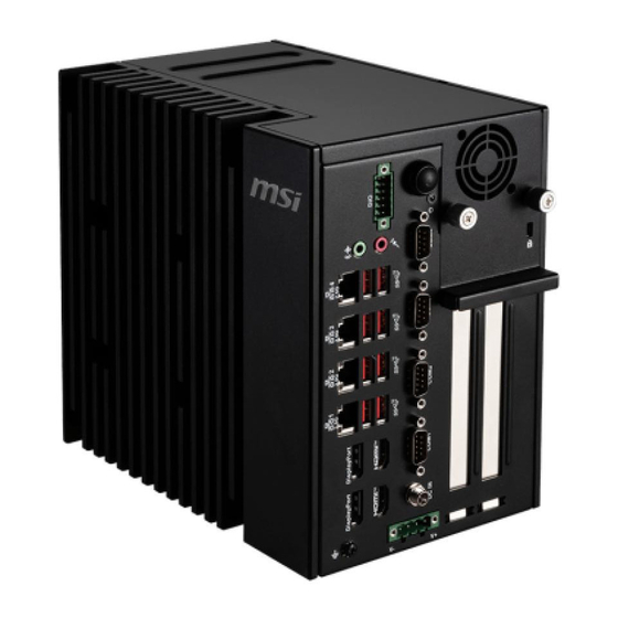
Page 12: System Overview
System Overview 4-Slot SKU1 2-Slot SKU2 SKU4 1-Slot SKU3 System Overview... -
Page 13: System I/O & Controls
System I/O & Controls (SKU1 Only) System Overview... - Page 14 DIO Port This Digital I/O connector is suitable for various industrial applications, including programmable logic devices and custom-embedded applications that extensively use GPIO. It can read data from environmental sensors (IR, video, temperature, 3-axis orientation, and acceleration) and output signals to DC motors (via PWM), audio devices, LCD displays, or LEDs for status indication.
- Page 15 2.5 Gbps LAN Jack The standard RJ-45 LAN jack is provided for connection to the Local Area Network (LAN). You can connect a network cable to it. Status Description No link SPEED Link/ Activity LED Linked LINK/ACT Yellow Data activity Blinking 10/100 Mbps Speed LED...
- Page 16 RS232/422/485 Serial Port: COM1~2 The serial port is a 16550A high speed communications port that sends/ receives 16 bytes FIFOs. You can attach a serial mouse or other serial devices directly to the connector. RS232 SIGNAL DESCRIPTION NDCD Data Carrier Detect NSIN UART Serial Input NSOUT...
-
Page 17: System Internal View
System Internal View Motherboard 2.5” SSD/HDD Brackets (MS-C9101) (SKU1~3 Only) Riser Board System Overview... -
Page 18: Me Overview
ME Overview System Dimensions SKU1 (4-Slot) Unit of measurement: mm 4.30 2.85 4.30 2.85 4.30 2.85 2.85 4.30 ME Overview... - Page 19 SKU1 (4-Slot, with Wall Mount Bracket) Unit of measurement: mm 16.50 ME Overview...
- Page 20 SKU2 (2-Slot) Unit of measurement: mm 4.30 2.85 4.30 2.85 4.30 4.30 2.85 2.85 ME Overview...
- Page 21 SKU2 (2-Slot, with Wall Mount Bracket) Unit of measurement: mm 16.50 ME Overview...
- Page 22 SKU3 (1-Slot) Unit of measurement: mm 4.30 2.85 4.30 2.85 4.30 2.85 4.30 1.00 2.85 ME Overview...
- Page 23 SKU3 (1-Slot, with Wall Mount Bracket) Unit of measurement: mm 16.50 1.00 ME Overview...
- Page 24 SKU4 (2-Slot) Unit of measurement: mm 4.30 2.85 4.30 2.85 2.85 4.30 4.30 1.00 2.85 ME Overview...
- Page 25 SKU4 (2-Slot, with Wall Mount Bracket) Unit of measurement: mm 16.50 1.00 ME Overview...
-
Page 26: Pcie And Pci Card Dimensions
PCIe and PCI Card Dimensions Supported PCIe and PCI Card Dimensions Card Type PCIe Card PCI Card Dimensions 195mm Length (X-axis) 155mm (W/ bracket) 118mm (W/ bracket) 112mm (W/ bracket) Height (Y-axis) 65mm (W/ bracket) ⚠ Important SKU1-4 support identical PCIe and PCI card dimensions. PCIe Card Bracket Filler Panel... -
Page 27: Motherboard Jumpers
Motherboard Jumpers ⚠ Important Avoid adjusting jumpers when the system is on; it will damage the motherboard. JATX1 ME_DIS1 JCMOS1 JCOM2 JCOM1 Jumper Name Default Setting Description COM1 Power Select Jumper JCOM1 1-2: 5V Power (Default) 2-3: 12V Power COM2 Power Select Jumper JCOM2 1-2: 5V Power (Default) 2-3: 12V Power... -
Page 28: Getting Started
Getting Started ⚠ Important All information is subject to change without prior notice. ∙ ∙ Before you remove or install any components, make sure the system is not turned on or connected to the power. The illustrations are provided for demonstrative purposes only. The appearance ∙... -
Page 29: System Covers
System Covers Removing System Top Cover 1. Loosen the thumbscrews to release the top cover. 2. Carefully push forward and lift the top cover to remove it from the system. ∙ Follow the above procedures in reverse order to install the cover. System Covers... -
Page 30: Removing System Side Cover
Removing System Side Cover Loosen and completely remove the screws to release the side cover. Follow the above procedures in reverse order to install the side cover. ∙ System Covers... -
Page 31: Cpu & Heatsink
CPU & Heatsink CPU Socket Introduction to the LGA1700 CPU The surface of the LGA1700 CPU has four notches and a golden triangle to assist in correctly lining up the CPU for motherboard placement. The golden triangle is the Pin 1 indicator. Locating CPU Socket CPU &... -
Page 32: Installing Cpu
Installing CPU Use appropriate ground straps, gloves and ESD mats to protect yourself from electrostatic discharge (ESD) while installing the processor. ⚽ https://youtu.be/KMf9oIDsGes ⚠ Important ∙ Always unplug the power cord from the power outlet before installing or removing the CPU. ∙... -
Page 33: Installing The Heatsink
Installing the Heatsink 1. Carefully remove the protective films from the thermal pads located on the bottom of the heatsink. 2. Gently lower the heatsink down and place it upon the system. 3. Tighten M4x8 screws and the spring-loaded screws in diagonal sequence. This ensures even pressure distribution and prevents warping. -
Page 34: Removing The Heatsink
Removing the Heatsink 1. Lay the system down on a flat, stable surface. 2. Identify and loosen the spring-loaded screws in the center of the heatsink. Side View ⚠ Important These screws are designed to be loosened but not removed. 3. -
Page 35: Memory Module
Memory Module DIMM1 DIMM2 DDR5 DIMM Thermal Pad Thickness Recommendations DIMM Type Single-sided DIMM Double-sided DIMM Location (chip on one side) (chips on both sides) (Thermal Pad) Closest to Motherboard 2.0mm 1.0mm In the Middle of Two DIMMs 2.25mm 1.25mm Installing Memory Module 1. -
Page 36: M.2 Slots
M.2 Slots Installing M.2 SSD (2280, M-Key) Feature ∙ Supports PCIe 4.0 x4 & SATA 3.0 signal (signal from PCH) ∙ Supports B+M Key PCIe x4/ SATA 3.0 module M2_M1 1. Loosen the M.2 screw from the motherboard. 2. Insert your M.2 SSD into the M.2 slot at a 30-degree angle. -
Page 37: Installing M.2 Wi-Fi Card (2230, E-Key, For Sku1 Only)
Installing M.2 Wi-Fi Card (2230, E-Key, for SKU1 Only) Feature ∙ Supports PCIe 4.0 x1, USB 2.0 signal 1. Loosen the M.2 screw from the motherboard. 2. Insert your M.2 Wi-Fi card into the M.2 slot at a 30-degree angle. 3. -
Page 38: Mini-Pcie Slot ( For Sku2 Only)
Mini-PCIe Slot ( for SKU2 Only) Installing Mini-PCIe Card 1. Loosen the riser screw from the motherboard. 2. Insert the card into the slot at a 45-degree angle. 45° 3. Push the card gently downwards and fasten it with the screw. Mini-PCIe Slot ( for SKU2 Only) -
Page 39: Ssd/Hdd Brackets (For Sku1~3)
2.5” SSD/HDD Brackets (for SKU1~3) Installing 2.5” HDD/ SSD (7mm) 1. Identify the components necessary for HDD/SSD installation. Drive Cage Drive Tray 2.5” HDD/SSD Thermal Pad 2. Fit the HDD/SSD into the drive tray. Be sure to put the HDD/SSD in the correct orientation. - Page 40 3. Remove the thermal pad from the backing paper. 4. Carefully attach it to the HDD/SSD. ∙ Check the following illustration for the exact location of the thermal pad. 5. After the thermal pad is in place, peel off the protective film. Protective Film Backing Paper 6.
- Page 41 7. Remove the system side cover. (Please refer to the "Removing System Side Cover" section.) 8. Flip over the system side cover and locate the mounting bracket. 9. Align the standoffs on the side of the drive cage with the hole on the mounting bracket, then pull the inner rail forwards till it locks into place.
- Page 42 12. Align the SATA data & power connector and connect to the HDD/SSD. 13. Connect the SATA signal & power connector to the motherboard to complete the installation. Follow the above procedures in reverse order to replace the HDD/SSD if needed. ∙...
-
Page 43: Pcie Expansion Card
PCIe Expansion Card Installing PCIe Expansion Card 1. Remove the filler panel from the chassis. 2. Check the card’s keyed components for correct alignment with the slot and lower the card into the slot. 3. Flip the latch outward and insert the card vertically into the slot, ensuring that the off-center notch at the bottom aligns with the slot. - Page 44 6. Place the bracket above the card and screw it to the back panel as indicated. Protective Bracket A protective bracket is provided to cut down on system vibrations that may damage the card. PCIe Expansion Card...
-
Page 45: Power Connector
Power Connector With a redundant power supply solution, users may feed the power through the DC power jack and/or through the 8V~48V Phoenix DC connector. Connecting DC Receptacle Connector 1. Locate the DC power connector on the front panel. 2. Connect a DC receptacle connector to it. Power Connector... -
Page 46: Dio Connector
DIO Connector Connecting DIO Switch Connector 1. Locate the DIO connector on the front panel. 2. Insert the DIO switch connector at a 45-degree angle. DIO Connector... -
Page 47: Wall Mount
Wall Mount Installing Wall Mount Bracket 1. Flip over the system and locate the bracket screw holes. 2. Place the brackets along the sides with screw holes aligned. 3. Fasten the screws to fix the brackets. Screws for Wall Mount Brackets Screw Type: M3x5 screw Wall Mount... -
Page 48: Bios Setup
BIOS Setup This chapter provides information on the BIOS Setup program and allows users to configure the system for optimal use. Users may need to run the Setup program when: ∙ An error message appears on the screen at system startup and requests users to run SETUP. - Page 49 Control Keys ← → Select Screen ↑ ↓ Select Item Enter Select Change Value Exit General Help Previous Values Optimized Defaults Save & Reset* Screenshot capture Scroll help area upwards <K> <M> Scroll help area downwards * When you press <F10>, a confirmation window appears and it provides the modification information.
-
Page 50: The Menu Bar
The Menu Bar ▶ Main Use this menu for basic system configurations, such as time, date, etc. ▶ Advanced Use this menu to set up the items of special enhanced features. ▶ Boot Use this menu to specify the priority of boot devices. ▶... -
Page 51: Main
Main HDD/SSD Information ∙ RAID (VMD) Disabled: Display HDD/SSD information as plugging in status. ∙ RAID (VMD) Enabled: Display "Not Present" only. *SATA_3 is for M.2 M key (SATA signal) ▶ System Date This setting allows you to set the system date. Use <Tab> key to switch between date elements. - Page 52 ▶ VMD Setup Menu (VMD Configuration) ▶ Enabled VMD Global Mapping Enables or disables Intel VMD mapping. Intel VMD enables direct control and management of NVMe SSDs from the PCIe bus without additional hardware adapters. ▶ Map This Root Port under VMD Enables or disables the mapping of the specified PCIe root port under Intel VMD control.
-
Page 53: Advanced
Advanced ▶ Full Screen Logo Display This BIOS feature determines if the BIOS should hide the normal POST messages with the motherboard or system manufacturer’s full-screen logo. [Enabled] BIOS will display the full-screen logo during the boot-up sequence, hiding normal POST messages. [Disabled] BIOS will display the normal POST messages, instead of the full- screen logo. - Page 54 ▶ CPU Configuration ▶ VT-d Enables or disables Intel VT-D (Intel Virtualization for Directed I/O) technology. ▶ Intel Virtualization Technology Enables or disables Intel Virtualization technology. [Enabled] Enables Intel Virtualization technology and allows a platform to run multiple operating systems in independent partitions. The system can function as multiple systems virtually.
- Page 55 ▶ Intel (R) SpeedStep (TM) Enhanced Intel SpeedStep® Technology enables the OS to control and activate performance states (P-States) of the processor. [Enabled] When enabled, Intel SpeedStep® technology is activated. This technology allows the processor to manage its power consumption via performance state (P-State) transitions. [Disabled] Disables this function ▶...
- Page 56 ▶ Super IO Configuration ▶ Serial Port 1/ 2/ 3/ 4 This setting enables or disables the specified serial port. » Device Settings This setting shows the address & IRQ of the specified serial port or parallel port. » Change Settings This setting is used to change the address &...
- Page 57 ▶ H/W Monitor (PC Health Status) These items display the current status of all monitored hardware devices/ components such as voltages, temperatures and all fans’ speeds. ▶ Thermal Shutdown This setting determines the behavior of the system when the CPU temperature reaches a predefined threshold.
- Page 58 ▶ Smart Fan Configuration ▶ SYSFAN This setting enables or disables the Smart Fan function. Smart Fan is an excellent feature which will adjust the CPU/system fan speed automatically depending on the current CPU/system temperature, avoiding the overheating to damage your system. The following item will display when SYSFAN1 is enabled. »...
- Page 59 ▶ Network Stack Configuration This menu provides Network Stack settings for users to enable network boot (PXE) from BIOS. ▶ Network Stack This menu provides Network Stack settings for users to enable network boot (PXE) from BIOS. The following items will display when Network Stak is enabled. »...
- Page 60 ▶ GPIO Group Configuration ▶ GPO0 ~ GPO3 These settings control the operation mode of the specified GPIO. Advanced...
- Page 61 ▶ PCIE ASPM settings This menu provide settings for PCIe ASPM (Active State Power Management) level for different installed devices. ▶ M2_M1/ RISER_PCIE1/ RISER_PCI/ RISER_M2_E1 Sets PCI Express ASPM (Active State Power Management) state for power saving. Lanes form PCH (RISER_PCI/ RISER_M2_E1): [Disabled] Disable this function.
-
Page 62: Boot
Boot ▶ Boot Option #1-3 This setting allows users to set the sequence of boot devices where BIOS attempts to load the disk operating system. Boot... -
Page 63: Security
Security ▶ Administrator Password Administrator Password controls access to the BIOS Setup utility. ▶ User Password User Password controls access to the system at boot and to the BIOS Setup utility. ▶ Chassis Intrusion Enables or disables recording messages while the chassis is opened. This function is ready for the chassis equips a chassis intrusion jumper(switch). - Page 64 ▶ PCH-FW Configuration This menu allows you to configure settings related to the PCH firmware. Firmware Information ME Firmware Version These settings show the firmware information of the Intel ME Firmware Mode ME (Management Engine). ME Firmware SKU ▶ ME State This menu controls the Intel®...
- Page 65 ▶ Firmware Update Configuration This menu will display when ME State is enabled. » ME FW Image Re-Flash Enables or disables the ME Firmware Image Re-flashing. » Local FW Update Enables or disables the capability to perform a firmware update. ▶...
- Page 66 » CPU Replaced Polling Disable Setting this option disables the CPU replacement polling loop. » HECI Message Check Disable This setting disables message check for BIOS boot path when sending messages. » MBP HOB Skip Setting this option will skip ME’s Memory-Based Protection (MBP) H0B region. »...
- Page 67 ▶ AMT Configuration Intel® Active Management Technology (Intel® AMT) is hardware-based technology for remotely managing and securing PCs out-of-band (OOB). ▶ USB Provisioning of AMT Enables or disables the ability to provision AMT using a USB device. ▶ Mac PASS Through Enables or disables the ability of AMT to pass through network traffic without altering the original MAC (Media Access Control) addresses of the network interface.
- Page 68 ▶ ASF Configuration » PET Progress Enables or disable the this item to receive PET Events. » WatchDog Enables or disable the watchdog timer. » OS Timer This item displays OS Timer. » BIOS Timer This item displays BIOS Timer. »...
- Page 69 ▶ One Click Recovery (OCR) Configuration » OCR Https Boot Enables or disables the use of HTTPS (Hypertext Transfer Protocol Secure) for the OCR boot process. When enabled, the OCR process will utilize HTTPS for enhanced security during the process of booting up the system. »...
- Page 70 ▶ Trusted Computing ▶ Security Device Support This item enables or disables BIOS support for security device. When set to [Disable], the OS will not show security device. ▶ SHA256/ SHA384 PCR Bank These settings enables or disables the SHA256 PCR Bank and SHA384 PCR Bank. ▶...
- Page 71 ▶ Serial Port Console Redirection ▶ Console Redirection Console Redirection operates in host systems that do not have a monitor and keyboard attached. This setting enables or disables the operation of console redirection. When set to [Enabled], BIOS redirects and sends all contents that should be displayed on the screen to the serial COM port for display on the terminal screen.
- Page 72 ▶ Console Redirection Settings (COM1) » Terminal Type To operate the system’s console redirection, you need a terminal supporting ANSI terminal protocol and a RS-232 null modem cable connected between the host system and terminal(s). You can select emulation for the terminal from this setting. [ANSI] Extended ASCII character set.
- Page 73 ▶ Secure Boot ▶ Secure Boot Secure Boot function can be enabled only when the Platform Key (PK) is enrolled and running accordingly. ▶ Secure Boot Mode Selects the secure boot mode. This item appears when Secure Boot is enabled. [Standard] The system will automatically load the secure keys from BIOS.
-
Page 74: Chipset
Chipset ▶ Primary Display Use the field to select the primary display of the system. ▶ Internal Graphics This setting enables or disables the internal graphics function. Available settings are: [Auto] The internal graphics will be automatically enabled or disabled. [Enabled] Enables the internal graphics. -
Page 75: Power
Power ▶ Restore AC Power Loss This setting specifies whether your system will reboot after a power failure or interrupt occurs. Available settings are: [Power Off] Leaves the computer in the power off state. [Power On] Leaves the computer in the power on state. [Last State] Restores the system to the previous status before power failure or interrupt occurred. - Page 76 ▶ LAN/ PCIE PME Enables or disables the system to be awakened from the power saving modes when activity or input signal of Intel LAN device and onboard PCIE PME is detected. ▶ RTC When [Enabled], your can set the date and time at which the RTC (real-time clock) alarm awakens the system from suspend mode.
-
Page 77: Save & Exit
Save & Exit ▶ Save Changes and Reset Save changes to CMOS and reset the system. ▶ Discard Changes and Exit Abandon all changes and exit the Setup Utility. ▶ Discard Changes Abandon all changes. ▶ Load Optimized Defaults Use this menu to load the default values set by the motherboard manufacturer specifically for optimal performance of the motherboard. -
Page 78: Gpio Wdt Programming
GPIO WDT Programming This chapter provides GPIO (General Purpose Input/ Output), WDT (Watch Dog Timer), programming guide. Abstract In this section, code examples based on C programming language provided for customer interest. Inportb, Outportb, Inportl and Outportl are basic functions used for access IO ports and defined as following. -
Page 79: General Purpose Io
// Set N_GPO1 address (bit 4) to 0 (output “low”). Outportb (0xA05, val); // Write back to N_GPO1 port. MSI Industrial Platform Computing Read input value from GPI Read the value from GPI port. Get the value of GPI address. -
Page 80: Watchdog Timer
// Write back WDT setting. Disable WDT val = Inportb (WDT_BASE + 0x05); // Read current WDT setting MSI Industrial Platform Computing val = val & 0xDF; // Disable WDT by set WD_EN (bit 5) to 0. Outportb (WDT_BASE + 0x05, val);...
Need help?
Do you have a question about the MS-C910 and is the answer not in the manual?
Questions and answers