
Subscribe to Our Youtube Channel
Related Manuals for Salamander Designs Arc AT/6P/G2


Summary of Contents for Salamander Designs Arc AT/6P/G2
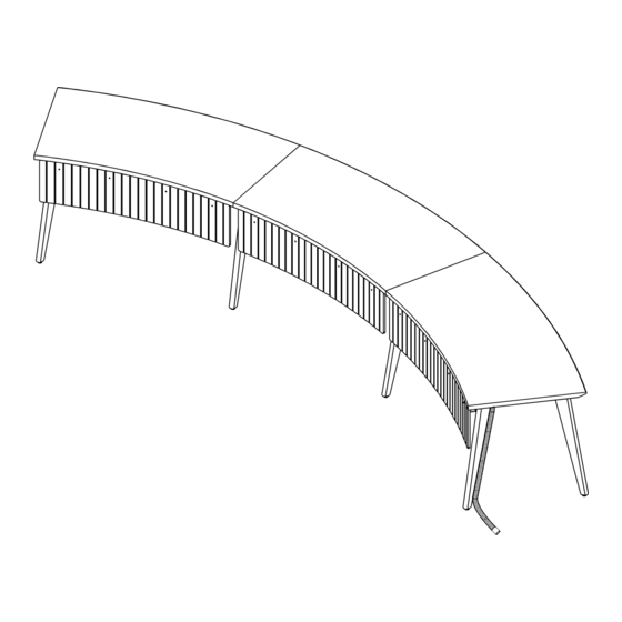
- Page 1 ASSEMBLY 14’ Arc™ Meeting Table (6 Person) AT/6P/G2 14’ Arc™ Meeting Table (6 Person) Assembly 501-780-6 v10.23 page 1 of 8...
- Page 2 PARTS PART NUMBER DESCRIPTION 205-6030 ARC Table Top Segment (12) 302-355 8-32 x 1/2” Modesty Panel Fastener (12) 300-485 1/4-20 x 1/2” Cable Raceway Mounting Screw (48) 300-585 1/4-20 x 3/4” Leg Mounting Screw P-305-590/BO/CM Table Leg with Wireloom P-305-590 Table Leg 305-585 Cable Raceway...
-
Page 3: Before You Begin
BEFORE YOU BEGIN Table will be assembled starting with the left (seated) segment. WIRELOOM ACCESSORIES Place table leg (D) with pre-installed wireloom at If your tops have cut-in accessories such as a desired location. Typically installed in the back cable port or charger be sure to select the tops in the order intended from left to right side of the table towards the center for wire seated position. - Page 4 2. Table Segment #1 A. Attach Legs Use (6) C screws to attach the two legs to the mating edge of top. Use (8) C screws to attach the two outer legs to the top. C X14 B. Acoustic Panel Attach the acoustic modesty panel to the table top using B screws.
- Page 5 3. Table Segment #2 A. Attach Legs B. Accoustic Panel Use (3) C screws per leg. Use (1) B screws per bracket. C X6 B X4 C. Join Table Segments Flip the table segment 2 and position it over the mounting plates of the standing table leg. Attach (3) C screws to each leg from underneath the table, connecting the two table segments.
- Page 6 4. Table Segment #3 A. Attach Legs B. Accoustic Panel Use (3) C screws per leg. Use (1) B screws per bracket. C X8 B X4 C. Join Table Segments Flip the table segment 3 and position it over the mounting plates of the standing table leg. Attach (3) C screws to each leg from underneath the table, connecting the two table segments.
- Page 7 5. Level Table Position table in the desired location and level if needed using the threaded leveling feet. CAUTION: When relocating the assembled table, exercise caution and ensure that each section is adequately supported during the move. Leveling Direction Threaded Leveling Foot 6.
- Page 8 7. Install Ports Place and secure ports and chargers into the designated openings on the tabletop. LIMITED WARRANTY FOR COMMERCIAL VIDEO DISPLAY STANDS AND MOUNTS Salamander is proud to stand behind our products with industry-leading warranties. Should you ever encounter any problem with your Salamander product, let us know.
Need help?
Do you have a question about the Arc AT/6P/G2 and is the answer not in the manual?
Questions and answers