Table of Contents
Advertisement
Quick Links
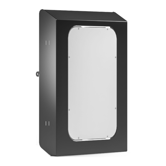
Surface Hub Battery Storage Case Installation
FPSA/MSB
Electronic Stand Installation see pages 2-4
Fixed Height Stand Installation see pages 5-7
PARTS
ID
QTY
A
2
B
4
C
1
D
8
E
1
F
1
G
6
H
1
I
4
A
F
Surface Hub Battery Storage Case
Part #
302-300
10-32 X 3/8" BUTTON HEAD CAP SCREWS
300-485
1/4-20 X 1/2" BUTTON HEAD SOCKET CAP SCREWS
400-080
5/32" HEX KEY
400-125
VELCRO ONE-WRAP STRAP, - 1/2 X 8" LONG
300-496
5/32 x 25mm HEX BIT
400-178
.261" DRILL BIT
300-515
1/4" ID X 5/8" OD NEOPRENE BONDED WASHER
400-170
1/8" HEX KEY
300-532
1/4-20 NE NYLON LOCK NUT
B
G
DESCRIPTION
C
H
D
I
501-738 v11.21
E
page 1 of 8
Advertisement
Table of Contents

Subscribe to Our Youtube Channel
Related Manuals for Salamander Designs FPSA/MSB


Summary of Contents for Salamander Designs FPSA/MSB
- Page 1 Surface Hub Battery Storage Case Installation FPSA/MSB Electronic Stand Installation see pages 2-4 Fixed Height Stand Installation see pages 5-7 PARTS Part # DESCRIPTION 302-300 10-32 X 3/8” BUTTON HEAD CAP SCREWS 300-485 1/4-20 X 1/2" BUTTON HEAD SOCKET CAP SCREWS 400-080 5/32”...
- Page 2 Installing on Electric Lift Mobile Stand Bracket Install Using the provided hex key, loosen the two screws indicated. NOTE: Do not remove these screws as they are used to support internal components. Loosen only enough to install the two L Brackets as shown at right. Tighten only enough to maintain orientation shown.
- Page 3 Secure Battery Attach Battery to Storage Case using four screws (#300-485) and four washers (#300-515), rubber side down. Tighten screws with hex key provided. BACKPACK TOP STORAGE CASE Install Battery and Storage Case Resecure with the 10-32 fasteners as shown on step 2. Attach the supplied hook and loop straps to manage wiring inside and to attach power cord from the battery when not charging.
- Page 4 Wire Management Manage cables carefully. Use cable ties to keep wires away from pinch points. Plug AC and DC cables and USB into their respective locations on the Surface Hub then run the cables through the Stand and connect to Battery. Route Cable from Display to Stand Manage cables through cable chain by pushing cable through finger keeper...
- Page 5 Installing on Fixed Height, Mobile Stand Determine Drill Locations Place the 11 x 17 drilling template provided over the Stand Cubby Cover and align the two horizontal lines on the template shown at left with the top and bottom edges of the slot in the Cubby Cover. Align the left edge of the template with the inside edge of the Cubby Cover slot.
- Page 6 Bracket Alignment Attach the Storage Case by inserting the support tabs into the two slots ensuring that the two L Brackets fall inside of the Storage Case. Gently push the Storage Case down until the support tabs are seated in the slots. Secure the Storage Case by installing the two 10-32 x 3/8”...
- Page 7 Install Cables and Storage Case – 1/4-20 x 1/2” Run Cables Through Stand SCREW (2x) Remove the Upper Rear Panel by first removing the two 1/4-20 x 1/2” screws and then tipping the Panel back enough to allow lifting the Panel off of the two Upper Rear Panel Studs.
Need help?
Do you have a question about the FPSA/MSB and is the answer not in the manual?
Questions and answers