Table of Contents
Advertisement
Quick Links
Advertisement
Table of Contents

Related Manuals for Husqvarna BT 90


Summary of Contents for Husqvarna BT 90
- Page 1 BT 90 Operator's manual 2-37...
-
Page 2: Table Of Contents
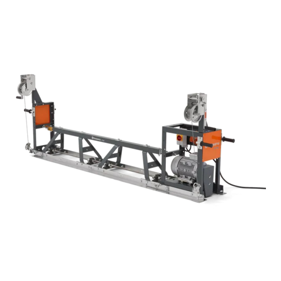
Contents Introduction..............2 Transportation, storage and disposal......25 Safety................5 Technical data.............. 26 Assembly................ 9 Declaration of Conformity..........36 Operation..............17 Declaration of Conformity..........37 Maintenance..............21 Trademarks..............37 Troubleshooting............23 Introduction Product description Intended use The product is a modular truss vibrating beam system The product is for professional operation only. - Page 3 Product overview 1. Handle 6. Truss screed section 2. Winch 7. Motor (BT 90 E) 3. Stretching screw 8. Operator's manual 4. Coupling 9. Type plate 5. Engine (BT 90 G) 10. Rating plate 992 - 002 - 11.10.2023...
- Page 4 Electric winches overview 1. Assembly plates for EWL and EWR including screws, washers and nuts 2. Control board assembly kit (plates, screw, nut, washer, bracket) Use protective gloves. 3. Electrical Winch Left (EWL) 4. Electrical Winch Right (EWR) 5. Control board and rubber damper Keep all body parts away from rotating 6.
-
Page 5: Safety
Type plate 1. Product type 2. Product number 3. Product weight 4. Serial number 5. Manufacturer 6. Rated power 7. Production year Product damage We are not responsible for damages to our product if: • the product is incorrectly repaired. •... - Page 6 • This product is not intended for use by persons • Make sure that there is no grease or oil on the (including children) with reduced physical, sensory handle. or mental capabilities, or lack of experience and • Do not use the product in areas where fire or knowledge.
- Page 7 • Gently guide the product to do the work. Do not • Exhaust fumes also contain unburned hydrocarbons push the product with force. Hold the product at the including benzene. Long-term inhalation can cause handles securely, but make sure that you control health problems.
- Page 8 The power plug must agree with the power outlet. Do safety devices are not in proper working order or are not do modifications to the plug. Do not use adapter damaged, speak to your Husqvarna service agent. plugs with grounded products. Power plugs without •...
-
Page 9: Assembly
• Do not hold the pneumatic air hose to lift or move the • Clean the product to remove dangerous material product. before you do the maintenance. • Do not disconnect a pneumatic air hose that is • Disconnect the spark plug cap before you do the pressurized. - Page 10 To install the BT 90 P truss screed 5. Move the truss screed sections together until the bolt (D) goes into the holder (F). sections To prevent resonance, install the shortest truss screed sections near to the drive unit if the screed configuration allows it.
- Page 11 To install the truss screed extension 7. Tighten the nuts (A) and the screws (B) on the plugs (F) with two 19 mm flat wrenches. 1. Remove the nuts (A). 8. Install the clamp (I) and tighten it with a screwdriver. 9.
- Page 12 To install the outrigger 2. Connect the rubber hose (A) to the 2 pneumatic truss screed sections. The outrigger is available as an optional accessory. Use the outrigger when the product is on support rails. The outrigger can be installed on the 2 ends of the product. Note: The outrigger cannot be used together with an extension.
- Page 13 3. Adjust the bellows (C) until the end of the joint (D) 6. Move the truss screed sections together until nut (H) shows. goes into the holder (G). 4. Install the joint to the product and install the screw 7. Turn the nut (H) with a 36 mm wrench. (E).
- Page 14 2. Install the skate and the 2 screws (A) to the product. 5. Turn the 2 screws (C) and the 2 nuts (D) to adjust the height of the skate. 3. Put the product with the bottom side down. 6. When the adjustment is done, tighten the 2 screws 4.
- Page 15 1. Remove the manual winches, the screws, the 2. Attach the left assembly plate (A). Use the screws, washer, the nuts and the assembly plates. the washers and the nuts. 3. Attach the right assembly plate A) and the assembly plate for the control board (B).
- Page 16 4. Attach the left electric winch (D) to the left assembly 6. Attach the right electric winch ( C) to the right plate. Use the screws, the washers and the nuts. assembly plate. Use the screws, the washers and the nuts. 5.
-
Page 17: Operation
8. Attach the control board (E) to the control board 9. Connect according to the description. assembly plate. Use the screws, the washers and the nuts. a) Connect cable socket F to the socket on one end of cable G. b) Connect cable socket D to the socket on the other end of cable G. - Page 18 To adjust the angle between the truss 4. Loosen the locknuts (B). screed sections CAUTION: Do not increase the angle to more than ±3% as this decreases the life of the shaft coupling. 1. Assemble the truss screed sections. Refer to Assembly on page 9 .
- Page 19 b) If the engine is warm or the ambient temperature • If the product is lifted and moved, do a check of is high, open the choke. the stretching screws and the locknuts before the operation continues. Tighten the stretching screws 5.
- Page 20 To set the speed of the forward movement Note: If you want to operate a circular area, the There are 2 different shafts on the winches. The speed winches can be put in different positions since the of the forward movement is different for the 2 shafts. product then will move in a circle.
-
Page 21: Maintenance
Maintenance Introduction Maintenance schedule WARNING: Note: Read and understand the If more than 1 time interval is identified in safety chapter before you do maintenance a table row, the shortest time interval is for the first on the product. maintenance only. Maintenance At the first start af- Daily... - Page 22 water must come on the carburetor, the 3. Clean the piston and the concrete vibrator body. fuel tank or the generator. 4. Lubricate the piston with oil. • Clean the external surfaces of the engine of a 5. Assemble the concrete vibrator. gasoline drive unit with water, but not a high- CAUTION: pressure washer.
-
Page 23: Troubleshooting
Troubleshooting Problem Drive unit Cause Solution The product does BT 90 P No air pressure. Do a check of the air pressure. not start. No air. Do a check of the air flow. The air lever is in the OFF Set the air lever to the ON position. position. - Page 24 Problem Drive unit Cause Solution The vibration BT 90 P Too low air pressure. Adjust the air pressure to the given values. speed is too low. Too low air flow. Adjust the air flow to the given values. There are leaks in the Examine the pneumatic air hoses.
-
Page 25: Transportation, Storage And Disposal
• When the product is no longer in use, send it to a Husqvarna dealer or discard it at a recycling location. WARNING: Do not lift a damaged product. -
Page 26: Technical Data
Technical data Technical data BT 90 E BT 90 G BT 90 P Voltage, V Phases Frequency, Hz Power, kW/hp @rpm 3/4.1 @2865 5/7.5 @2900 – Full load current, A Engine brand, type Honda, GX270 Maximum length, m/ft 20/65.6 20/65.6 25/82 Operation air pressure, bar 3–6 Air consumption for each truss screed meter, 0.26 /min... - Page 27 Total length, Operation Total width, Height, mm/in. Weight, kg/lb mm/in. length, mm/in. mm/in. 0.75 m truss screed sec- 378/14.9 845/33.2 750/29.5 420/16.5 420/16.5 tion, electric/gasoline 1 m truss screed section, 378/14.9 1095/43.1 1000/39.4 420/16.5 32/70.5 electric/gasoline 2 m truss screed section, 378/14.9 2095/82.5 2000/78.7...
- Page 28 Product dimensions BT 90 E 980 mm/38.6 in. 560 mm/22 in. 545 mm/21.5 in. BT 90 G 980 mm/38.6 in. 560 mm/22 in. 610 mm/24 in. 992 - 002 - 11.10.2023...
- Page 29 BT 90 P 970 mm/38 in. 355 mm/14 in. 610 mm/24 in. 992 - 002 - 11.10.2023...
- Page 30 BT 90 P 1 m/3.3 ft. 1000 mm/39.4 in. 378 mm/14.9 in. 420 mm/16.5 in. BT 90 P 2 m/6.6 ft. 2000 mm/78.7 in. 378 mm/14.9 in. 420 mm/16.5 in. BT 90 P 3 m/9.8 ft. 3000 mm/118.1 in. 378 mm/14.9 in.
- Page 31 Truss screed section, 0.5 m/1.6 ft. 378 mm/14.9 in. 497 mm/19.5 in. 420 mm/16.5 in. Truss screed section, 0.75 m/2.4 ft. 378 mm/14.9 in. 746 mm/29.3 in. 420 mm/16.5 in. Truss screed section, 1 m/3.2 ft. 378 mm/14.9 in. 1000 mm/39.4 in. 420 mm/16.5 in.
- Page 32 Truss screed section, 2 m/6.5 ft. 378 mm/14.9 in. 2000 mm/78.7 in. 420 mm/16.5 in. Truss screed section, 3 m/9.8 ft. 378 mm/14.9 in. 3000 mm/118.1 in. 420 mm/16.5 in. 992 - 002 - 11.10.2023...
- Page 33 Outrigger 362 mm/14.25 in. B-299 mm/11.8 in. 300 mm/11.8 in. Skate Min 119 mm/4.69 in. 30 mm/1.18 in. 66.5 mm/2.62 in. Max 157 mm/6.18 in. 1000 mm/39.37 in. 15 mm/0.59 in. 992 - 002 - 11.10.2023...
- Page 34 Non-vibrating extension 421 mm/15.79 in. 420 mm/15.79 in. 500 mm/19.69 in. Crown invert bracket 371 mm/14.6 in. 430 mm/16.93 in. 267 mm/10.51 in. 420 mm/16.53 in. Pneumatic crown invert bracket 992 - 002 - 11.10.2023...
- Page 35 371 mm/14.6 in. 430 mm/16.93 in. 267 mm/10.51 in. 420 mm/16.53 in. 992 - 002 - 11.10.2023...
-
Page 36: Declaration Of Conformity
Declaration of Conformity EC Declaration of Conformity We, Husqvarna AB, SE-561 82 Huskvarna, Sweden, tel: +46-36-146500, declare on our sole responsibility that the product: Description Concrete Compactor, Vibrating Beam Brand Husqvarna Type/Model BT 90G, BT 90P BT 90G/E-, BT 90P-screed section... -
Page 37: Declaration Of Conformity
Declaration of Conformity EC Declaration of Conformity We, Husqvarna AB, SE-561 82 Huskvarna, Sweden, tel: +46-36-146500, declare on our sole responsibility that the product: Description Concrete Compactor, Vibrating Beam Brand Husqvarna Type/Model BT 90E BT 90G/E-screed section Identification Serial numbers dating from 2021 and onwards... - Page 38 992 - 002 - 11.10.2023...
- Page 39 992 - 002 - 11.10.2023...
- Page 40 www.husqvarnaconstruction.com Original instructions 1140378-26 Rev. B 2023-10-20...
Need help?
Do you have a question about the BT 90 and is the answer not in the manual?
Questions and answers