Subscribe to Our Youtube Channel
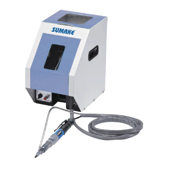
Summary of Contents for Sumake SF30T Series
- Page 1 INSTRUCTION MANUAL SF30T series ITEM NO.: AUTOMATIC SCREW SUPPLIER SF30T series-I-1301A-YM...
-
Page 2: Table Of Contents
Table of Contents I. About SF30T 1. Features………………………………………………………………..…. P3 2. Specifications…………………………………………………………..….P3 3. Working condition…………………………………………………….……P3 II. Safety precautions 1. Warning………………………………………………………………..…….P4 2. Safety…………………………………………………………………………P4 III. Installment 1. Preparation…………………..…………………………………………..….P6 2. Tryout…………………………………….………..……………………..….P8 3. Normal Operation…………………………….….………………………..P10 IV. Adjustment and replacement 1. Air volume adjustment……………………………….…………………..P10 2. Adjustment of escapement speed……………………..…………………P11 3. -
Page 3: About Sf30T
I. About SF30T 1. Features 1. Designed for speed, stability, and convenience. 2. Improving screw driving speed and work efficiency by integrating pneumatic/ electrical screwdriver, high-tech automatic feeder, and high precision jaw. 3. The jaw is customized by particular screw and working environment to provide a stable operation. -
Page 4: Safety Precautions
II. Safety precautions To avoid endangering the lives and property of the individual and other and to prevent occurrence of dangerous, please follow and read this instruction. 1. Warning: 【Prohibition Sign】fire, electric shock or personnel injury or death may occur if not observed. - Page 5 Prohibit hand in screw feeder when working to avoid dangerous Please use specific power. Remove the power plug if the machine is to remain idle for a long period of time. Do not place non-spec screws into the hopper. Do perform regular maintenance of the machine as scheduled.
-
Page 6: Installment
III. Installment 1. Preparation 1. Connect the screw delivery hose, screwdriver plug and signal cable to the feeder unit. See <Fig.1> Take a balance of the driver unit for easier fastening. While taking balance, make sure that the signal cable and air hose do not contact with hook or balancer wire. Care should be taken to prevent excessive bending or twisting of hoses and cables, since this can cause damage or disconnection. - Page 7 Since this unit has no provisions for adjusting air pressure, pressure must be controlled at the source. ( PULL UP FIRST, AND ROTATE) see <Fig.3> Air Pressure Adjusting <Fig.3> 4. Screw delivery timer check. Check screw delivery timer setting on the front of the feeder unit. Standard operation setting is 0.5. see <Fig.4>...
-
Page 8: Tryout
2. Tryout 1. Open the hopper and cover and load hopper with a small quantity of screw. See <Fig.6> <Fig.6> Load Screws Max Volume 2. Turn power switch on. See<Fig.7> The power and motor pilot lamps will light, the feeding track will start reciprocating and screw will be fed into the chute. - Page 9 Confirmation of driver bit rotation. Check the screwdriver rotate after pressing lever and is there any abnormal sounds.<Fig.8> Please check screwdriver switch is correct or not- clockwise or counterclockwise. <Fig.9> <Fig.9> Check Screw Feeding Check Rotating <Fig.10> Confirm the correct rotating setting Check torque range is suitable or not ...
-
Page 10: Normal Operation
3. Normal Operation 1. After all preparatory steps have been competed, load screw into the hopper. <Fig.11> 2. Turn power switch on. <Fig.12> 1. Load Screws <Fig.11> 2. Push Power Switch <Fig.12> Press lever to feed first screw. NOTE:Press lever for 1 second then release to feed. Make sure screw reach tip of screwdriver and the thread expose from Jaw. -
Page 11: Adjustment Of Escapement Speed
2. Adjustment of escapement speed If the shutter of escapement works badly, then need to adjust speed value by procedures as below. Change shutter for rightward speed, adjust right valve Change shutter for leftward speed, adjust left valve. <Fig.14> right valve left valve 3. -
Page 12: Regulate Plate Adjustment
4. Regulate plate adjustment: If the regulate plate is too high or low, please adjust by 4mm hex-wrench and 8mm wrench to adjust. <Fig.16> Adjust screw Torque adjustment or BIT replacement The pipeline of screwdriver must be separated then disassemble before BIT replacement or torque adjustment. -
Page 13: Troubleshooting
V. Troubleshooting 1. Screw can’t reach tip of screwdriver : The screw jammed or delivery hose disconnected. (1). Check whether there is miscellaneous material and tube didn’t connect or not. The air volume is too weak to feed screw from screw feeder to screwdriver. (2). -
Page 14: Feeding Through Track Is Not Smooth
Both sides of jaw After removing Jaw head Screw of cylinder hose joint 4. Feeding through track is not smooth: The vibration equipment rail is dirty (1). Please use cotton dip alcohol to clean. The regulation plate position is not appropriate or screw tolerance is too big. (2). -
Page 15: Maintenance
VI. Maintenance To make screw feeder and screwdriver set can be used in long state. Please lubricate and clean dirty parts regularly. Please also replace BIT regularly to avoid stripping. ★ .If working environment is harsh or frequent operation, please short time of maintenance. - Page 16 EU Declaration of Conformity (DOC) SUMAKE INDUSTRIAL CO., LTD. 4F, No. 351, Yangguang St., Neihu District, Taipei City, Taiwan declare in sole responsibility that the equipment Equipment: AUTOMATIC SCREW FEEDER Model/ Serial No.: SNF-A1, SNF-A2, SNF-A3, SNF-A4, SNF-A8, SNF-A9, SNF-A10, SNF-A11, SNF-A12, SNF-A13, SF40TH, SF30A,...


Need help?
Do you have a question about the SF30T Series and is the answer not in the manual?
Questions and answers