
Related Manuals for Sumake SF30A Series


Summary of Contents for Sumake SF30A Series
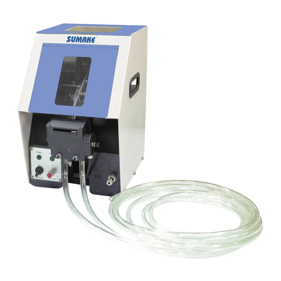
- Page 1 INSTRUCTION MANUAL SF30A series ITEM NO.: AUTOMATIC SCREW SUPPLIER SF30A series-I-1212B-YM...
-
Page 2: Table Of Contents
Table of Contents I. About SF30A 1. Features…………………………………………………………..…. P3 2. Specifications……………………………………………………..….P3 II. Installment 1. Preparation………………………………………………………..….P4 2. Tryout……………………………………………………………..….P6 3. Normal Operation…………………………………………………..P8 4. After Operation……………………………………………………..P9 5. Maintenance………………………………………………………….P9 III. Adjustment and Replacement 1. Air Pressure Adjustment…………………………………………….P10 2. Screw Deliver time Adjustment……………………………………..P11 3. Screw Deliver Air Volume Adjustment……………………………...P11 4. -
Page 3: About Sf30A
I. About SF30A 1. Features 1. Designed for speed, stability, and convenience. 2. Improving screw driving speed and work efficiency by integrating pneumatic/ electrical screwdriver, high-tech automatic feeder, and high precision jaw. 3. The jaw is customized by particular screw and working environment to provide a stable operation. -
Page 4: Installment
II. Installment 1. Preparation 1. Connect the screw delivery hose, air hose and signal cable to the feeder unit Take a balance of the driver unit for easier fastening. While taking balance, make sure that the signal cable and air hose do not contact with hook or balancer wire. - Page 5 2. Connect feeder unit to compressed air source with an air hose supplied. Air pressure for the feeder unit is 4-5 kg/cm Air hose 3. Since this unit has no provisions for adjusting air pressure, pressure must be controlled at the source.
-
Page 6: Tryout
2. Tryout 1. Open the hopper and cover and load hopper with a small quantity of screw. Load Screws Max Volume 2. Turn power switch on. The power and motor pilot lamps will light, the feeding track will start reciprocating and screw will be fed into the chute. - Page 7 4. Confirmation of driver bit rotation. The driver should rotate when the bit is pressed against a flat surface while the Y-pipe is compressed. Check for any abnormal sounds during rotation. The driver rotates clockwise only. Check Screw Feeding Check Rotating 5.
-
Page 8: Normal Operation
3. Normal Operation 1. After all preparatory steps have been competed, load screw into the hopper. 2. Turn power switch on. 1. Load Screws 2. Turn Power Switch 3. Hold the driver unit and press the Y-pipe manually to confirm that a screw is seen at the tip of the driver at the first time. -
Page 9: After Operation
4. After Operation 1. Lubrication Loosen the needle valve of the oiler while idling the driver. After confirming oil flow of 3 to 5 drops through the window, retighten the needle valve. Then, idle the driver unit alone for one or two minutes to allow oil to circulate. -
Page 10: Adjustment And Replacement
3. Draining water from filter Water accumulated in the filter should be drained by loosening the drain cock. Draining water III. Adjustment and Replacement 1. Air Pressure Adjustment Air pressure supply to feeder unit must be within 4-5 kg /cm Air pressure adjustment... -
Page 11: Screw Deliver Time Adjustment
2. Screw Deliver time Adjustment Screw delivery time is the time for the screw to pass through the screw delivery hose to the driver jaw. Adjust screw delivery time by setting the timer on front of the feeder. 0 on the dial indicates the shortest time (approx. -
Page 12: Torque Adjustment
4. Torque Adjustment To release the nut. Re-assembly the front part. Turn the bit to expose a hose in which you'll insert a #1 Phillips screwdriver. Rotate the hand screwdriver clockwise to increase torque and counter clockwise to decrease torque. REMEMBER: The numbers 1, 2, 3 on the housing do not indicate actual torque. -
Page 13: Bit Replacement
5. Bit Replacement To release the nut. Re-assembly the front part. Use a negative driver and push the ring forward. Keep pushing the ring forward and pull the bit out. And, still keep pushing the ring forward and insert the new bit. Lubricate and assembly it. - Page 14 EU Declaration of Conformity (DOC) SUMAKE INDUSTRIAL CO., LTD. 4F, No. 351, Yangguang St., Neihu District, Taipei City, Taiwan declare in sole responsibility that the equipment Equipment: AUTOMATIC SCREW FEEDER Model/ Serial No.: SNF-A1, SNF-A2, SNF-A3, SNF-A4, SNF-A8, SNF-A9, SNF-A10, SNF-A11, SNF-A12, SNF-A13, SF40TH, SF30A,...
- Page 16 NOTE www.SUMAKE.com www.AIRCOMPRESSOR.com.tw...
Need help?
Do you have a question about the SF30A Series and is the answer not in the manual?
Questions and answers