Edge-Core OAP101 Quick Start Manual
Outdoor access point
Hide thumbs
Also See for OAP101:
- User manual (100 pages) ,
- User manual (102 pages) ,
- Quick start manual (6 pages)
Table of Contents
Advertisement
Quick Links
Quick Start Guide
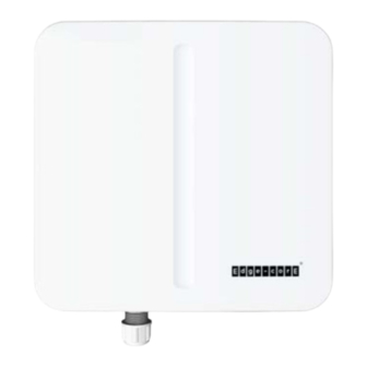
Outdoor Access Point
OAP101 (T) | OAP101-6E (T)
1.
OAP101 (T) or OAP101-6E (T) access point
2.
Mounting bracket and 4 x M6 screws
3.
DC terminal plug
4.
3 x Cable glands
1
2
3
Warning:
For a safe and reliable installation, use only the
accessories and screws provided with the device. Use of other
accessories and screws could result in damage to the unit. Any
damages incurred by using unapproved accessories are not
covered by the warranty.
Note:
The drawings in this document are for illustration only
and may not match your particular model.
1
Mount the Device
a. Mounting on a Wall
1
1.
At the installation location on the wall, use the mounting bracket to
mark four holes for the wall plugs and screws. The bracket must be
installed with the marking "UP" at the top.
1
2
7
4
5
8
2
Package Contents
3
4
5.
2 x Steel-band clamps for pole mount (2.5 inch diameter max.)
6.
Screw kit—4 screws and 4 plugs
7.
QR code card
Overview
1.
Grounding point
2.
DC In port: 48 VDC
3.
Uplink (PoE) port: RJ-45 2.5GBASE-T connection to 802.3at PoE
6
4.
LAN port: 1 Gbps LAN connection
5.
Console port
6.
Moisture protective vent
7.
Power/Status LED:
Yellow green: On (power OK), Blinking (boot up)
Blue: On (cloud managed)
Purple: Blinking (uplink activity in cloud managed mode)
Orange: Blinking (uplink activity in stand-alone mode)
8.
Restart/Reset button:
A quick press restarts the system.
Press and hold for 5 seconds resets to factory defaults.
Installation
Drill four holes for the wall plugs, and then insert the plugs and tap
them flush with the wall surface.
Note:
screws, or 4.5 mm (±0.2 mm) holes for nylon wall plugs.
2.
Use the included M6 screws to attach the mounting bracket to the
device.
3.
With its ports facing down, slide the device down onto the pre-
installed screws until it snaps into its secured position. Do not let go
of the device until you confirm that it is secure.
b. Mounting on a Pole
1.
Use the included M6 screws to attach the mounting bracket to the
device.
2.
Feed the two steel-band clamps through the pole-mount bracket
mounting points.
– 1 –
5
6
Drill 2.5 mm (±0.2 mm) holes for M3 self-tapping
2
1
3
7
E092023-MR-R01
150200002630A
Advertisement
Table of Contents

Subscribe to Our Youtube Channel
Related Manuals for Edge-Core OAP101


Summary of Contents for Edge-Core OAP101
- Page 1 Outdoor Access Point OAP101 (T) | OAP101-6E (T) Package Contents OAP101 (T) or OAP101-6E (T) access point 2 x Steel-band clamps for pole mount (2.5 inch diameter max.) Mounting bracket and 4 x M6 screws Screw kit—4 screws and 4 plugs...
- Page 2 Quick Start Guide Fasten the steel-band clamps around the pole to secure the AP to Check AP LED the pole. Ground the Device When operating normally, the Power/Status LED should be on yellow green. Blinking indicates the device is booting up. Ground the device by connecting a ground wire to the grounding Initial Setup and AP Registration point on the device and to nearby good earth.
- Page 3 Selection of other channels is not possible. .com). If you want to register the AP to your own TIP OpenWiFi SDK, contact oxherd@edge-core.com to change the default The operation of this device is prohibited on oil platforms, cars, URL.
- Page 4 BLE 2.4 GHz: 802.15.1 5 GHz Radio IEEE 802.11a/ac/n/ax The frequency and maximum transmitted power limit in EU are listed 6 GHz Radio IEEE 802.11a/ac/n/ax (OAP101-6E (T) only) as below: Bluetooth Radio IEEE 802.15.1 2412-2472 MHz: 20 dBm 5470-5725 MHz: 30 dBm Radio Frequencies 2.4–2.4835 GHz...
Need help?
Do you have a question about the OAP101 and is the answer not in the manual?
Questions and answers