Table of Contents
Advertisement
Advertisement
Table of Contents

Related Manuals for Edge-Core ECW5211-L


Summary of Contents for Edge-Core ECW5211-L
-
Page 1: Quick Installation Guide
Quick Installation Guide ECW5211-L Enterprise Access Point... -
Page 2: Copyright Notice
Quick Installation Guide ECW5211-L ENGLISH Copyright Notice This document is protected by USA copyright laws and other laws and is the property of Edgecore Networks Corporation. You may not copy, reproduce, distribute, publish, display, perform, or modify any part of this publication in any form or by any means without prior written permission from Edgecore Networks Corporation. -
Page 3: Fcc Caution
Quick Installation Guide ECW5211-L ENGLISH FCC CAUTION This equipment has been tested and found to comply with the limits for a Class B digital device, pursuant to Part 15 of the FCC Rules. These limits are designed to provide reasonable protection against harmful interference in a residential installation. - Page 4 Quick Installation Guide ECW5211-L ENGLISH CE CAUTION Hereby, Edgecore Networks Corporation declares that the radio equipment type ECW5211-L is in compliance with Directive 2014/53/EU. Frequency Range and Transmit Power Frequency range (MHz) Max. transmit power (dBm) 2412-2472 20 dBm 5150-5350...
- Page 5 Quick Installation Guide ECW5211-L ENGLISH Taiwan NCC Statement 根據 NCC 低功率電波輻射性電機管理辦法 規定: 第十二條 經型式認證合格之低功率射頻電機,非經許可,公司、商號或使用者均不得擅自變更頻率、 加大功率或變更原設計之特性及功能。 第十四條 低功率射頻電機之使用不得影響飛航安全及干擾合法通信;經發現有干擾現象時,應立即 停用,並改善至無干擾時方得繼續使用。前項合法通信,指依電信法規定作業之無線電通 信。低功率射頻電機須忍受合法通信或工業、科學及醫療用電波輻射性電機設備之干擾。 在 5.25 ~ 5.35 秭赫頻帶內操作之無線資訊傳輸設備,限於室內使用。 For UNII 產品 (5GHz WLAN/WIFI) [警語內容] 使用此產品時應避免影響附近雷達系統之操作。 MPE [警語] 「電磁波曝露量 MPE 標準值 1mW/cm2,本產品使用時建議應距離人體 28cm」 減少電磁波影響,請妥適使用...
-
Page 6: Package Contents
5. Cushion x 4 This Quick Installation Guide provides instructions 6. Power Adapter (12V) x 1 on how to install the ECW5211-L and to get the network up and running with basic configurations. It is recommended to keep the original packing material for possible future shipment when repair or maintenance is required. -
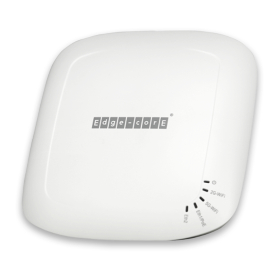
Page 7: Hardware Overview
Quick Installation Guide ECW5211-L ENGLISH Hardware Overview ECW5211-L Front View ECW5211-L Side View ②... - Page 8 Quick Installation Guide ECW5211-L ENGLISH Item Name Description Power / Status LED Indicator: (a) Steady green light indicates a proper connection to a power source and normal operation. (b) The LED Indicator will start blinking when the Reset button is...
-
Page 9: Hardware Installation
(a) Mounting on a Wall 1. Set two screws in the wall 128 mm (5.0 in.) apart. 2. Slide ECW5211-L’s wall mounting slots down onto the screws so that the unit is secure. (b) Mounting on a Ceiling T-Bar 1. Use the included screws to attach two ceiling-mount T-bar clips to the back of ECW5211-L. - Page 10 Connect the 12V/1A power adapter to the DC power jack. Using a different power adapter may damage this system. To verify the wired connection between ECW5211-L and you switch / router, please also check the LED indicator of the respective network devices.
-
Page 11: Initial Configuration
ENGLISH Initial Configuration To set up the ECW5211-L for the first time, administrators need to perform initial configuration to assign an IP address and other information necessary for the AP to communicate with the local gateways. Step 1. Login to the AP The AP has a web-based interface for configuration and management. - Page 12 Quick Installation Guide ECW5211-L ENGLISH 3. System Overview page of the WMI will appear after login. Step 2. Change the administrator’s password Click on the Utilities icon on the main menu, and select the Change Password tab. Enter the New Password and retype it in the Re-enter New Password field.
- Page 13 Quick Installation Guide ECW5211-L ENGLISH Step 3. Configure General Information Go to System General page (Home > System > General) to configure general information for the AP. ⑧...
- Page 14 Quick Installation Guide ECW5211-L ENGLISH Connect the AP to the Network The following instructions are the basic steps to establish the wireless coverage of your network. The AP will connect to the wired network through its Eth2 port and enable wireless access to your network.
- Page 15 Quick Installation Guide ECW5211-L ENGLISH Step 2. Activate the first SSID for Wi-Fi access 2.1) By default, one Service Set Identifier (SSID) is enabled with the Radio A (RF Card A) and one SSID is enabled with the Radio B (RF Card B). As shown on the VAP Overview page (Home > Wireless > VAP Overview), Virtual Access Point No.1 (VAP-1) profile represents the first SSID available.
- Page 16 Quick Installation Guide ECW5211-L ENGLISH 2.2) Click on the State (Enabled) of VAP-1 to configure the profile. This will bring up the following VAP Configuration page. 2.3) Select the specific VAP profile (in this case, “RF Card A : VAP-1”). The basic settings of the VAP are collected in the profile as follows: ...
- Page 17 Quick Installation Guide ECW5211-L ENGLISH Network Mode: mode – the VAP operates transparently (i.e. no NAT, no DHCP) such that client Bridge devices will be assigned a dynamic IP address from a DHCP server on the LAN side. The source IP address of client traffic seen by the uplink gateway/switch will remain the original IP address of the client (in this case, 192.168.1.31, as shown in the diagram below).
- Page 18 Quick Installation Guide ECW5211-L ENGLISH - VLAN ID is supported only when the VAP is in Bridge mode. - DHCP Profile and DHCP Server are activated only when the VAP is set to NAT mode. Note: - If the VAP is in NAT mode, the CAPWAP Tunnel Interface will only work in two states: Disable (No Tunnel) or Split Tunnel.
- Page 19 (in the Beacon management frame) when multiple physical APs broadcast the same ESSID. After ECW5211-L's network configuration is completed, please remember to change the IP Address of your PC Connection Properties back to its original settings in order to ensure that your PC functions properly in its real network environments.
Need help?
Do you have a question about the ECW5211-L and is the answer not in the manual?
Questions and answers