Table of Contents
Advertisement
Quick Links
Advertisement
Table of Contents

Related Manuals for Luxman C-10X


Summary of Contents for Luxman C-10X
- Page 1 CONTROL AMPLIFIER C-10X...
-
Page 2: Table Of Contents
Contents Precautions ············································································································· 1 Features of This Unit ································································································ 2 Names and Functions ······························································································ 4 Connections ·········································································································· 12 Operations ············································································································· 18 How to use Remote Control ·················································································· 20 Block Diagram ······································································································· 29 Specifications ········································································································ 32 Before Asking for Repair Services ·········································································· 33... -
Page 3: Precautions
Precautions CONTROL AMPLIFIER C-10X Installation place Batteries Install this unit in a location where good ventilation and heat Warning: Batteries used for the remote control shall not be radiation are assured. Especially, installation of this unit where exposed to excessive heat such as sunshine, fire or the like. -
Page 4: Features Of This Unit
Engine System — Loopless chassis structure ODNF, LUXMAN’s original amplification feedback circuitry, has This unit features a loop-less chassis, independently con- been renewed, and LIFES, our newly developed feedback structed to eliminate increases in ground impedance due to engine, is incorporated right at the heart of this amplifier, chassis current. - Page 5 A selector relay with high sound quality is used in the key Our original high rigidity 27 mm pitch RCA terminals and XLR point of the LUXMAN amplifier, which enhances the separa- terminals manufactured by Neutrik. tion and crosstalk performance.
-
Page 6: Names And Functions
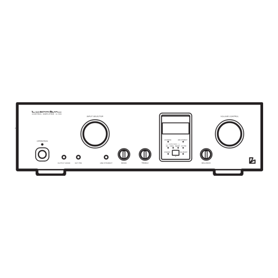
Names and Functions Front view 1. Operation button (OPERATION) 4. Display window Changes this unit from standby to operational. Displays the operation status of this unit. This unit becomes operational after turning this unit to This status is composed of 8 indicators, an input display standby by setting the main power button to the ON/ and a volume display. - Page 7 CONTROL AMPLIFIER C-10X 6. Balance control (BALANCE) 9. Tone control for bass (BASS) Adjusts the relative volume of the right and left channels. Controls the frequency characteristics of the low-frequency Rotating the control counterclockwise gradually cuts the range. volume of the right channel, rotating the control clockwise Setting this control to the center position provides flat gradually cuts the volume of the left channel.
- Page 8 Names and Functions Front panel 11. External pre button (EXT PRE) When a device such as a CD player that the sound volume adjustment does not function is connected, the sound This is an input selector button that selects the external volume adjustment of the device cannot be controlled by pre-input terminals (EXT PRE) on the rear panel.
- Page 9 CONTROL AMPLIFIER C-10X 12. Output mode selection button (OUTPUT MODE) Switches between three output modes; unbalanced output, balanced output and bi-amp output. Every time this button is pressed, the phase changes as follows: UNBAL → BAL → BI-AMP → UNBAL → ...
- Page 10 Names and Functions Display window 1. Input display (IN:) 4. Balanced indicator (BAL) Displays the input terminal selected using the input selector Lights up when the balanced output terminal is selected for or remote control. the output mode. 2. Volume display (VOL:) 5.
- Page 11 CONTROL AMPLIFIER C-10X 8. Bi-amp indicator (BI-AMP) 11. Line straight indicator (LINE STRAIGHT) Lights up when the bi-amp output is selected for the output mode. Lights up when the line straight button is on. 9. Balanced phase inversion indicator When the line straight button is set to on, the loudness function (BAL INVERT) cannot be operated from the supplied remote control.
- Page 12 (LINE-1, LINE-2, LINE-3) (CONTROL OUT) Coaxial input terminal to receive unbalanced audio signal Connects a LUXMAN’s device with a control input terminal at line level. using a commercially available 3.5 mm monaural mini-jack Connect between the unbalanced output terminal of an cable.
- Page 13 CONTROL AMPLIFIER C-10X 8. Main power button (MAIN POWER) 12. Balanced input terminals/INPUTS (BAL LINE-1, BAL LINE-2, BAL LINE-3) Turns this unit to the standby state. When this button is set to ON/STANDBY, the standby indicator on the front panel XLR connector input terminal to receive balanced audio sig- lights up to show that this unit turns to the standby state.
-
Page 14: Connections
Connections Normal stereophonic reproduction CD/SACD PLAYER CD/SACD PLAYER CD/SACD PLAYER TRIGGER IN TRIGGER IN POWER AMP 1 POWER AMP 2 SPEAKER SYSTEM 1 SPEAKER SYSTEM 2... - Page 15 When connection is conducted from a product made by other than LUXMAN, make sure that the trigger output is 12 V. Connecting to the power supply The trigger input of this unit should be 12 volts, the power Insert the accessory power supply cable plug into an AC out- consumption is 13 mA.
- Page 16 Connections Bi-amplifier/stereophonic reproduction CD/SACD PLAYER CD/SACD PLAYER CD/SACD PLAYER L-LOW R-LOW L-HIGH R-HIGH TRIGGER IN TRIGGER IN POWER AMP POWER AMP HIGH SPEAKER SYSTEM...
- Page 17 When connection is conducted from a product made by other device to the balanced input terminal. than LUXMAN, make sure that the trigger output is 12 V. Connect between the unbalanced output terminals of an The trigger input of this unit should be 12 volts, the power input device such as a CD player and the unbalanced input consumption is 13 mA.
- Page 18 Connections External pre playback AV AMP/PRE AMP TRIGGER IN TRIGGER IN POWER AMP 1 POWER AMP 2 SPEAKER SYSTEM 1 SPEAKER SYSTEM 2...
- Page 19 CONTROL AMPLIFIER C-10X External pre playback How to connect between the external pre- input terminals and an input device such as an AV amplifier When using this unit with the external pre-input, only the unbalanced output terminal is enabled. Therefore, no sound will be generated if connecting an input device to the balanced input terminal.
-
Page 20: Operations
Operations Before operation Tone controls 1. Ensure that all connections have been correctly performed. This unit has tone controls for the low and high frequency (Normal playback cannot be achieved with incorrect con- ranges. nections of R or L.) The low frequency range is effective at 300 Hz or lower. 2. - Page 21 CONTROL AMPLIFIER C-10X Memory Prohibition display and caution This unit stores the following items when the operation button When tried to change the setting and failed, an error display is off or the main power is off: shown in the table below will be displayed.
-
Page 22: How To Use Remote Control
How to use Remote Control Remote controller (RA-20) 1. Operation button (OPERATION) 2. Input selector (LINE-1, LINE-2, LINE-3, BAL-1, BAL-2, Turns this unit to the operating state after turning off the BAL-3) standby indicator at the standby state. Pressing this button again at the operating state turns the unit to the standby Selects the unbalanced input terminal or balanced input ter- state. - Page 23 CONTROL AMPLIFIER C-10X 3. Output mode selection button 5. External pre button (EXTERNAL PRE) (OUTPUT MODE) This is an input selector button that selects the external pre-input terminals (EXT PRE) on the rear panel. Switches between three output modes; unbalanced output, On: Outputs directly the pre-amplifier or AV amplifier output balanced output and bi-amp output.
- Page 24 How to use Remote Control Remote controller (RA-20) 9. Preset button (PRESET), (2) When the enter button is pressed, 3+ and 2– of BAL-1 starts blinking and the phase inversion setting of BAL Enter button (ENTER) LINE-1 of the balanced input becomes available. (Display Determines the adjustment or the setting value.
- Page 25 CONTROL AMPLIFIER C-10X (4) When the next time the enter button is pressed, the (10) When the next time the enter button is pressed, the changed BAL LINE-1 setting is determined, 3+ and 2– display goes back to the setting of (2) and the phase...
- Page 26 How to use Remote Control (5) When the next time the enter button is pressed, the (11) When the next time the enter button is pressed, the changed BAL LINE-1 setting is determined, the level of changed LINE-1 setting is determined, the level of BAL-2 starts blinking and the level adjustment of BAL LINE-2 starts blinking and the level adjustment of LINE-2 becomes available.
- Page 27 CONTROL AMPLIFIER C-10X PRESET PRESET PRESET (Setting end) ENTER ENTER PRESET PRESET ▲,▼ ▼ ENTER ENTER PRESET PRESET ▲,▼ ENTER ENTER PRESET PRESET ▲,▼ ▼ ENTER ENTER ▲,▼ PRESET PRESET ENTER ENTER PRESET PRESET ▼ ▲,▼ ENTER ENTER ▲,▼ PRESET...
- Page 28 How to use Remote Control Remote controller (RA-20) How to preset the bi-amp output mode/ Pressing ▼ decreases the sound volume of L-Hi ch in BI-AMP steps of 0.5 dB. Adjustment is available in the range of ±6 dB. (1) When the preset button is pressed in a state where the Example) Pressing ▼...
- Page 29 CONTROL AMPLIFIER C-10X 10. Loudness button (LOUDNESS) (6) At this point, when the enter button is pressed, the display returns to the adjustment of (2) and the adjustment of When this button is pressed in a state where the volume L-Hi ch becomes available again.
- Page 30 How to use Remote Control Remote control Dry cell [How to load dry cells] The remote control should be aimed at the remote sensor of this unit within the specified angle range as shown in the 1. Remove the battery cover on the rear of the remote control. illustration.
-
Page 31: Block Diagram
Block Diagram CONTROL AMPLIFIER C-10X... - Page 32 Block Diagram...
- Page 33 CONTROL AMPLIFIER C-10X RECTIFIER RECTIFIER RECTIFIER...
-
Page 34: Specifications
Specifications Input sensitivity LINE : 180 mV/1 V output, 1 kHz, load 50 kΩ BAL LINE : 180 mV/1 V output, 1 kHz, load 100 kΩ LINE → BAL LINE : 180 mV/1 V output, 1 kHz, load 100 kΩ BAL LINE →... -
Page 35: Before Asking For Repair Services
While in use, this unit may display phenomena which may be confused as malfunctions. Before contacting your country’s official LUXMAN distributor for repair services, please read the operating instructions and operating instructions for any connected input and through output devices and check the troubleshooting table below. If the cause of the malfunction cannot be identified, please contact your dealer. - Page 36 LUXMAN CORPORATION AG00238G16A 1-3-1 Shinyokohama, Kouhoku-ku, Yokohama-shi, Kanagawa 222-0033, Japan Printed in Japan...
Need help?
Do you have a question about the C-10X and is the answer not in the manual?
Questions and answers