Table of Contents
Advertisement
Quick Links
Advertisement
Table of Contents

Subscribe to Our Youtube Channel
Related Manuals for Luxman L-595ASE


Summary of Contents for Luxman L-595ASE
- Page 1 INTEGRATED AMPLIFIER L-595ASE Owner`s Manual...
-
Page 2: Table Of Contents
Contents Precautions ············································································································· 1 Features of This Unit ································································································ 2 Names and Functions ······························································································ 4 Connections ·········································································································· 10 Operations ············································································································· 14 How to use Remote Control ·················································································· 16 Block Diagram ······································································································· 19 Specifications ········································································································ 20 Before Asking for Repair Services ·········································································· 21... -
Page 3: Precautions
Precautions INTEGRATED AMPLIFIER L-595ASE Installation place Sound is not generated shortly after the This unit should be installed in a well-ventilated location to power supply is turned on. enable heat dissipation because it is an A-class amplifier and This amplifier is equipped with a timed muting circuit to pro- generates considerable heat. -
Page 4: Features Of This Unit
Feedback — Beeline construction The output section features LUXMAN’s original distortion-only LUXMAN’s Beeline construction ensures that the audio signal negative feedback system which enables a high-speed pri- path takes the optimum shortest route from input to speaker mary slew rate and ultra-wide audio bandwidth. Only distor- output. - Page 5 INTEGRATED AMPLIFIER L-595ASE Non-angled circuitry 18 mm pitch RCA terminals After carefully considering the delicate nature of the audio sig- We have used 18 mm pitch RCA input terminals for inputs nal flow, non-angled circuit board tracking has been adopted other than LINE-1 to support high quality audio cables with to achieve smooth signal transmission.
-
Page 6: Names And Functions
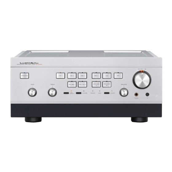
Names and Functions Front panel 10 11 1. Operation button (OPERATION) 3. Input selectors/indicators (INPUT SELECTOR) This is the power on/off button. These buttons select an input source from devices such When wiring or connection is performed, be sure to turn off as a CD player, SACD player, D/A converter or tuner con- this button. - Page 7 INTEGRATED AMPLIFIER L-595ASE 4. Speaker selectors/indicators 7. Tone control for treble (SPEAKERS) TONE CONTROL (TREBLE) Selects either of 2 speaker systems, A or B, located at the Controls the frequency characteristics of the high-frequency rear panel. A is the default setting. When A is pressed in range.
- Page 8 Names and Functions Front panel 10 11 9. Loudness button/indicator (LOUDNESS) 11. Monaural indicator (MONO) Turns on and off a function that corrects for the charac- Lights up when the monaural button is on. teristics of human ears that have difficulty in listening to low-frequency and high-frequency sounds when the sound The subsonic and monaural functions can be toggled only volume is low.
- Page 9 INTEGRATED AMPLIFIER L-595ASE 12. Separate button/indicator (SEPARATE) 13. Balance control (BALANCE) Separates the pre-amplifier and main-amplifier from each Adjusts the relative volume of the right and left channels. other. Rotating the control counterclockwise gradually cuts the OFF (Separate indicator off): volume of the right channel, rotating the control clockwise Returns this unit to normal integrated amplifier mode.
- Page 10 Names and Functions Rear panel 1. Signal ground (ground terminal) 3. LINE-1, LINE-2, LINE-3, and LINE-4 (SIGNAL GROUND) input terminals (unbalanced) (LINE-1, LINE-2, LINE-3, and LINE-4) The ground terminal is for a device such as analog player connected to this unit. This terminal is used to reduce noise Used for line level signal inputs from CD players, SACD when other devices are connected.
- Page 11 INTEGRATED AMPLIFIER L-595ASE 5. Main input terminals (MAIN IN) 9. Speaker terminals (SPEAKERS) Provides input to the main-amplifier section when the Use these terminals to connect to your speaker system(s), pre-amplifier and main-amplifier are separated by setting the R speaker terminals connect to the right side and the the SEPARATE selector to on.
-
Page 12: Connections
Connections CD/SACD PLAYER D/A CONVERTER – – – – ANALOG PLAYER SPEAKER SYSTEM ( A ) SPEAKER SYSTEM ( B ) - Page 13 INTEGRATED AMPLIFIER L-595ASE Before connecting How to connect CD players, SACD players, D/A converters, tuners and other devices Before connecting other devices, connect the jack side of the accessory power cable to the AC inlet of this unit. Connect between the output terminals of the CD player,...
- Page 14 Connections CD/SACD PLAYER D/A CONVERTER – – – – ANALOG PLAYER SPEAKER SYSTEM ( A ) SPEAKER SYSTEM ( B )
- Page 15 INTEGRATED AMPLIFIER L-595ASE How to connect to analog players How to connect PRE OUT/MAIN IN terminal Connect between the output terminals of an analog player and the PHONO terminals of this unit with 2 (R and L) RCA Either the pre-amplifier or main-amplifier can be separately cables.
-
Page 16: Operations
Operations Before operation Tone controls 1. Ensure that all connections have been correctly per- This unit has a tone controls for the low- and high frequency formed. (Normal playback cannot be achieved with ranges. incorrect connections of R, L, ! or @.) The low frequency range is effective at 300 Hz or lower. - Page 17 INTEGRATED AMPLIFIER L-595ASE Memory This unit stores the following items when the power is off: Item Default INPUT Selected source SPEAKERS Selected speaker SUBSONIC on/off MONO on/off LOUDNESS on/off LINE STRAIGHT on/off SEPARATE on/off Memory reset The following operations restore all the settings to the factory defaults.
-
Page 18: How To Use Remote Control
How to use Remote Control Remote control (RA-17A) 1. Operation button (OPERATION) 4. Separate button (SEPARATE) This is a power on/off button. Separates the pre-amplifier and main-amplifier sections When wiring or connection is performed, be sure to turn the from each other. unit off using this button. - Page 19 INTEGRATED AMPLIFIER L-595ASE 7. Subsonic button (SUBSONIC) 10. CD/SACD player operation buttons (CD/SACD PLAYER) Turns on and off a function which cuts ultra-low frequencies outside the audible range to prevent ultra-low range noise These buttons are used to control the supported CD/SACD from adversely affecting audible frequency range signals.
- Page 20 How to use Remote Control Remote control The remote control should be aimed at the remote sensor of this unit within the specified angle range as shown in the illustration. 30° 30° Effective distance: approx. 5 meters Dry cell [How to load dry cells] 1.
-
Page 21: Block Diagram
Block Diagram INTEGRATED AMPLIFIER L-595ASE... -
Page 22: Specifications
Specifications 30 W + 30 W (8 Ω) Rated output 4 Ω - 2 Ω stable for music via single speaker pair. Total harmonic distortion 0.007 % (8 Ω, 1 kHz for both channels simultaneously, line straight on) 0.06 % (8 Ω, 20-20 kHz for both channels simultaneously, line straight on) Pre-amplifier PHONO (MM) : 2.5 mV/47 kΩ... -
Page 23: Before Asking For Repair Services
LUXMAN distributor for repair services, please read the operating instructions for any connected input and output devices and check the troubleshooting table below. If the cause of the malfunction cannot be identified, please contact your dealer. After LUXMAN’s rep- resentatives have accepted your request for repair services, inspection fees and transportation expenses may be claimed, even though the unit may be found to be operating normally. - Page 24 LUXMAN CORPORATION, JAPAN AG00987E95A 1-3-1 Shinyokohama, Kouhoku-ku, Yokohama-shi, Kanagawa 222-0033, Japan Printed in Japan...
Need help?
Do you have a question about the L-595ASE and is the answer not in the manual?
Questions and answers