Table of Contents
Advertisement
Quick Links
Advertisement
Table of Contents

Related Manuals for Luxman L-507Z


Summary of Contents for Luxman L-507Z
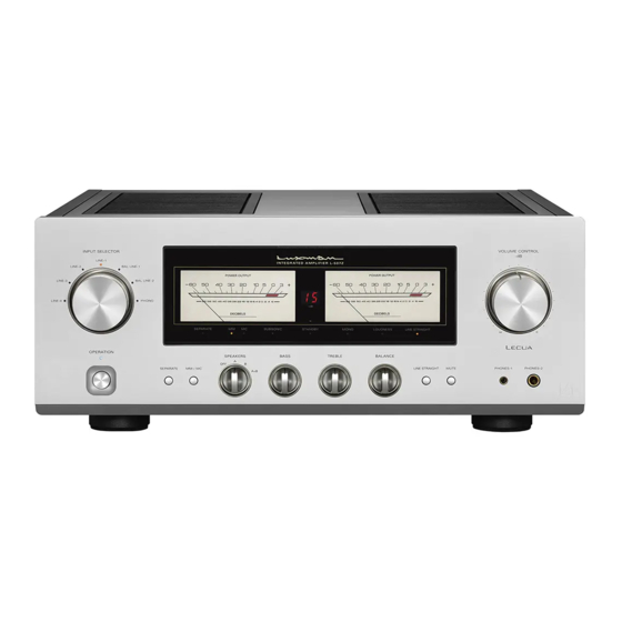
- Page 1 INTEGRATED AMPLIFIER L-507Z Owner`s Manual...
-
Page 2: Table Of Contents
Contents Precautions ············································································································· 1 Features of This Unit ································································································ 2 Names and Functions ······························································································ 4 Connections ·········································································································· 12 Operations ············································································································· 16 How to use Remote Control ·················································································· 18 Block Diagram ······································································································· 20 Specifications ········································································································ 21 Before Asking for Repair Services ·········································································· 22... -
Page 3: Precautions
Precautions INTEGRATED AMPLIFIER L-507Z Installation place Sound is not generated shortly after the power supply is turned on. Install this unit in a location where good ventilation and heat radiation are assured. Especially, installation of this unit where This amplifier is equipped with a timed muting circuit to pro- direct sunlight is present, where the temperature rises exces- tect the output. -
Page 4: Features Of This Unit
Beeline construction –87 dB with no deterioration in sound quality over the full range of the volume control. LUXMAN’s Beeline construction ensures that the audio signal path takes the optimum shortest route from input to speaker LIFES — Luxman Integrated Feedback output. - Page 5 INTEGRATED AMPLIFIER L-507Z Phono amplifier Cast-iron insulators This unit is equipped with an integral phono amplifier adopted For stability and support, this product features cast iron feet FET 2 parallel + OP amp compatible with the MM/MC car- with vibration reducing density gradient.
-
Page 6: Names And Functions
Names and Functions Front panel 1. Operation button (OPERATION) 3. Input selector (INPUT SELECTOR) Turns the power on and off (standby state). When wiring Selects an input device, such as a CD player, an SACD or connection is performed, be sure to turn off this button. player, a D/A converter, or a tuner connected to each input terminal. - Page 7 INTEGRATED AMPLIFIER L-507Z 5. Display window 12. Line straight button (LINE STRAIGHT) Displays the operation status of this unit. Enhances the purity of the sound quality by bypassing cir- This display is composed of 8 indicators, sound volume in- cuits such as balance control and tone control.
- Page 8 Names and Functions Front panel 15. Tone control for bass TONE CONTROL 17. Cartridge button (MM/MC) (BASS) Selects the gain level of the equalizer amplifier (an amplifier circuit necessary for playing an analog records). Controls the frequency characteristics of the low-frequency Each time this button is pressed, the selection will toggle range.
- Page 9 INTEGRATED AMPLIFIER L-507Z 18. Separate button (SEPARATE) Separates the pre-amplifier and main-amplifier each other. OFF (Separate indicator off): Returns this unit to normal integrated amplifier mode. ON (Separate indicator on): Feeds external signals from the MAIN IN terminal on the rear panel to the main-amplifier section.
- Page 10 Names and Functions Display window 1. Separate indicator (SEPARATE) 3. MM cartridge indicator (MM) Lights up when the separate button is set to on. Lights up when the cartridge button is set to MM. 2. Power meters 4. MC cartridge indicator (MC) Indicate the output of the L channel on the left side and the Lights up when the cartridge button is set to MC.
- Page 11 INTEGRATED AMPLIFIER L-507Z 6. Standby indicator (STANDBY) 11. Line straight indicator (LINE STRAIGHT) Lights up when the connected AC cable is plugged into a Lights up when the line straight button is on. wall socket and the operation button is set to off (standby state).
- Page 12 Names and Functions Rear panel 9 10 11 1. Signal ground 4. Pre-out terminals (PRE OUT) (Ground terminal) (SIGNAL GROUND) These terminals are used to obtain the output of the preamplifier. A bi-amp connection can be performed with The ground terminal is for a device such as analog player a combination of an external power amplifier because thes connected to this unit.
- Page 13 10. Control input terminal (CONTROL IN) Connects a LUXMAN’s device with a control output terminal using a commercially available 3.5-mm monaural mini-jack cable. This connection enables the infrared receiver circuit...
-
Page 14: Connections
Connections CD/SACD PLAYER D/A CONVERTER – – – – ANALOG PLAYER SPEAKER SYSTEM ( A ) SPEAKER SYSTEM ( B ) - Page 15 When connection is conducted from a product made by oth- er than LUXMAN, make sure that the trigger output is 12 V. The trigger input of this unit should be 12 volts, the power consumption is 13 mA.
- Page 16 Connections CD/SACD PLAYER D/A CONVERTER – – – – ANALOG PLAYER SPEAKER SYSTEM ( A ) SPEAKER SYSTEM ( B )
- Page 17 INTEGRATED AMPLIFIER L-507Z How to connect an analog player Connect the output terminals of an analog player and the PHONO terminals of this unit with 2 (R and L) pin-plug ca- bles. For most analog players, the ground wire from the pho- no motor or the tone arm should be connected to the ground terminal of this unit.
-
Page 18: Operations
Operations Before operation Balance control operation 1. Ensure that all connections have been correctly per- The balance control enables users to adjust the balance of formed. (Normal playback cannot be achieved with incor- sound volume between the right and left channels. rect connections of R, L, ! or @.) When the balance adjustment is not required, the balance 2. - Page 19 INTEGRATED AMPLIFIER L-507Z Memory This unit stores the following items when the power is off: Item Default INPUT Selected source METER on/off Sound volume indicator on/off SUBSONIC on/off MONO on/off LOUDNESS on/off LINE STRAIGHT on/off SEPARATE on/off MM/MC MM/MC Memory reset...
-
Page 20: How To Use Remote Control
How to use Remote Control Remote control (RA-17A) 1. Operation button (OPERATION) OFF (Separate indicator on): Returns this unit to normal integrated amplifier mode. Turns the power on and off (standby state). When wiring ON (Separate indicator off): or connection is performed, be sure to turn off this button. Feeds external signals from the MAIN IN terminal on the rear panel to the main-amplifier section. - Page 21 INTEGRATED AMPLIFIER L-507Z 7. Subsonic button (SUBSONIC) 11. Volume control switches (VOLUME, i, o) Cuts ultra-low frequencies outside the audible range to prevent ultra-low range noise from adversely affecting the Adjusts the sound volume. audible range. • Pressing i increases the sound volume in steps of 1 dB.
-
Page 22: Block Diagram
Block Diagram RECTIFIER RECTIFIER RECTIFIER RECTIFIER RECTIFIER RECTIFIER REG. REG. REG. -
Page 23: Specifications
Specifications INTEGRATED AMPLIFIER L-507Z Rated output 110 W+110 W (8 Ω) 210 W+210 W (4 Ω) Total harmonic distortion 0.007 % (8 Ω, 1 kHz for both channels simultaneously, line straight on) 0.03% (8 Ω, 20 - 20 kHz for both channels simultaneously, line straight on) -
Page 24: Before Asking For Repair Services
While in use, this unit may display phenomena which may be confused as malfunctions. Before contacting your country’s official LUXMAN distributor for repair services, please read the operating instructions for any connected input and output devices and check the troubleshooting table below. If the cause of the malfunction cannot be identified, please contact your dealer. After LUXMAN’s representatives have accepted your request for repair services, inspection fees and transportation expenses may be claimed, even though the unit may be found to be operating normally. - Page 25 MEMO INTEGRATED AMPLIFIER L-507Z...
- Page 26 MEMO...
- Page 28 LUXMAN CORPORATION, JAPAN AG00238G04A 1-3-1 Shinyokohama, Kouhoku-ku, Yokohama-shi, Kanagawa 222-0033, Japan Printed in Japan...
Need help?
Do you have a question about the L-507Z and is the answer not in the manual?
Questions and answers