Table of Contents
Advertisement
Quick Links
Advertisement
Table of Contents

Related Manuals for EXFO IQS-2400


Summary of Contents for EXFO IQS-2400
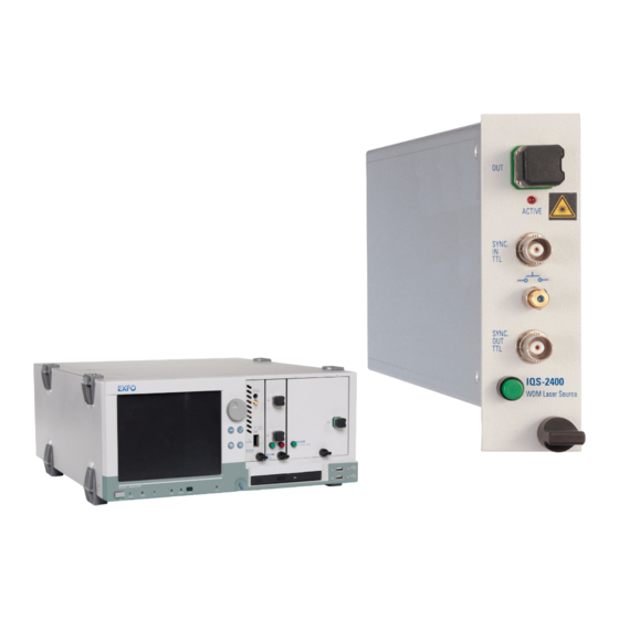
- Page 1 IQS-2400 IQS-2400 for IQS Platforms...
- Page 2 Engineering Inc. (EXFO). Information provided by EXFO is believed to be accurate and reliable. However, no responsibility is assumed by EXFO for its use nor for any infringements of patents or other rights of third parties that may result from its use.
-
Page 3: Table Of Contents
Contents Contents Certification Information ......................v 1 Introducing the IQS-2400 WDM Laser Source ..........1 Main Features .........................1 Safety Features ........................4 Typical Applications ........................6 Conventions ..........................7 2 Safety Information ..................9 3 Getting Started with Your WDM Laser Source ......... 11 Inserting and Removing Test Modules ..................11... - Page 4 Recycling and Disposal (Applies to European Union Only) ............67 9 Troubleshooting ..................69 Solving Common Problems ....................69 Viewing Online Documentation ....................70 Finding Information on the EXFO Web Site ................70 Contacting the Technical Support Group ................71 Transportation ........................72 10 Warranty ......................73 General Information ......................73 Liability ..........................73...
-
Page 5: Certification Information
F.C.C. Information Electronic test equipment is exempt from Part 15 compliance (FCC) in the United States. However, compliance verification tests are systematically performed on most EXFO equipment. Information Electronic test equipment is subject to the EMC Directive in the European Union. - Page 6 DECLARATION OF CONFORMITY Application of Council Directive(s): 73/23/EEC - The Low Voltage Directive 89/336/EEC - The EMC Directive And their amendments Manufacturer’s Name: EXFO Electro-Optical Engineering Inc. Manufacturer’s Address: 400 Godin Avenue Quebec, Quebec Canada G1M 2K2 (418) 683-0211 Equipment Type/Environment: Test &...
-
Page 7: Introducing The Iqs-2400 Wdm Laser Source
WDM Laser Source Main Features The IQS-2400 WDM Laser Source is a DFB laser source configured at a wavelength set at the time of purchase. However, you can adjust this wavelength within a ± 1 nm tuning range around the ITU-T wavelengths. - Page 8 Introducing the IQS-2400 WDM Laser Source Main Features The IQS-2400 WDM Laser Source features wavelength tuning capabilities for each of the ITU-T grid wavelengths, coherence control through a small signal, and direct current modulation with a triangular or square waveform. DFB laser diode manufacturers can also choose to integrate their own lasers into the IQS-2400 WDM Laser Source.
- Page 9 Introducing the IQS-2400 WDM Laser Source Main Features The IQS-2400 WDM Laser Source can operate in the following modes: Normal mode provides access to total wavelength- and power-tuning ranges, maintaining full control of the output power (automatic power control). High Wavelength Stability mode enables you to set wavelength and power-tuning resolution with picometer accuracy through laser temperature and current steps.
-
Page 10: Safety Features
Introducing the IQS-2400 WDM Laser Source Safety Features Safety Features To comply with laser safety regulations, each IQS-2400 WDM Laser Source is supplied with special security features. Interlock Connector The IQS-2400 WDM Laser Source is equipped with a remote interlock connector so you can install a security switch or panic button. - Page 11 Instrument is locked: Open interlock icon Five-Second Safety Delay The IQS-2400 WDM Laser Source application provides a five-second safety delay between the instrument activation and actual light emission. During this five-second delay, you may cancel the activation of the laser by using the instrument activation/deactivation switch, by opening the interlock circuit or by using the software key button.
-
Page 12: Typical Applications
WDM passive components. It is ideal for production environments and offers unequaled long-term wavelength stability. Place more than one IQS-2400 WDM Laser Source in an IQS Platforms and obtain the versatility and reliability you need for optical fiber amplifier testing and network qualification. -
Page 13: Conventions
Introducing the IQS-2400 WDM Laser Source Conventions Conventions Before using the product described in this manual, you should understand the following conventions: ARNING Indicates a potentially hazardous situation which, if not avoided, could result in death or serious injury. Do not proceed unless you understand and meet the required conditions. -
Page 15: Safety Information
Safety Information ARNING Do not install or terminate fibers while a light source is active. Never look directly into a live fiber and ensure that your eyes are protected at all times. ARNING Use of controls, adjustments and procedures for operation and maintenance other than those specified herein may result in hazardous radiation exposure. -
Page 17: Getting Started With Your Wdm Laser Source
Getting Started with Your WDM Laser Source Inserting and Removing Test Modules AUTION Never insert or remove a module while the controller unit and its expansion units are turned on. This will result in immediate and irreparable damage to both the module and unit. To insert a module into the controller or expansion unit: 1. - Page 18 6. While applying slight pressure to the module, turn the retaining screw knob (located at the bottom of the panel) clockwise until the knob is horizontal. This will secure the module into its “seated” position. IQS-2400...
- Page 19 Note: You can insert IQ modules into your controller or expansion unit; the IQS Manager software will recognize them. However, the IQS-2400 locking mechanism (retaining screw) will not work for IQ modules. To remove a module from your controller or expansion unit: 1.
- Page 20 3a. Slide the top of the protective cover into the upper grooves of the unit. 3b. Snap the cover into place by pushing the retaining screw knob. AUTION Failure to reinstall protective covers over empty slots will result in ventilation problems. IQS-2400...
-
Page 21: Starting The Wdm Laser Source Application
Starting the WDM Laser Source Application Starting the WDM Laser Source Application Your IQS-2400 WDM Laser Source module can be configured and controlled from its dedicated IQS Managerapplication. Note: For details about IQS Manager, refer to the IQS platform user guide. - Page 22 Note: To start the corresponding monitor window at the same time, click Start App. & Monitor. The window opens on the Monitors function tab. The main window (shown below) contains all the commands required to control the WDM Laser Source: Title bar Function Data tabs display Parameter definition controls Status IQS-2400...
- Page 23 Getting Started with Your WDM Laser Source Starting the WDM Laser Source Application Data Display Interlock circuit status indicator Spectral and power values Source status indicator Source control mode Temperature and Reference current values values Depending on the setup, the displayed units (nm/THz, dBm/mW) will change and some items may appear in bright colors or be grayed out.
- Page 24 Remote: Module controlled remotely, but local commands can also be used. Lockout: Module controlled remotely only. Module/unit status Current date and time For more information about automating or remotely controlling the IQS-2400 WDM Laser Source, refer to your platform user guide. IQS-2400...
-
Page 25: Entering Values Using Sliders And Numeric Boxes
Getting Started with Your WDM Laser Source Entering Values Using Sliders and Numeric Boxes Entering Values Using Sliders and Numeric Boxes Many parameters in IQS Manager and module applications can be set using the following tools. Slider Fine-tuning Numeric box button Navigation buttons Slider: Drag it to the desired value on the scale below. -
Page 26: Exiting The Application
To close the application from the main window: Click in the top right corner of the main window. Click the Exit button located at the bottom of the function bar. To close all currently running applications: From IQS Manager, click Close All Applications. IQS-2400... -
Page 27: Setting Up The Wdm Laser Source
Setting Up the WDM Laser Source Selecting a Control Mode The IQS-2400 WDM Laser Source offers the following control modes: Mode Explanation Display Normal To maximize output power During laser stabilization, stability. spectral value (wavelength or frequency) and power are Default mode used to tune displayed in dark green;... - Page 28 This mode (50 % duty cycle) Modulation uses half the average power available from the source module. It controls current during the “on” cycle of the signal. The tuning range for temperature and current are the same as in High Wavelength Stability mode. IQS-2400...
- Page 29 Setting Up the WDM Laser Source Selecting a Control Mode Interlock circuit status indicator Spectral and power values Source status indicator Source control mode Temperature and current values Reference values The spectral value shown on the data display is either the wavelength or the frequency of the signal emitted.
-
Page 30: Setting Modulation (For Dither And On/Off Modulation)
1. From the main window, select the Settings function tab. 2. Select the Control and Modulation tab. 3. For the On/Off control mode, select the source synchronization mode: internal or external from the Synchronization section. Note: Synchronization can only be internal with Dither Modulation control mode. IQS-2400... - Page 31 Setting Up the WDM Laser Source Setting Modulation (for Dither and On/Off Modulation) 4. From the Frequency section, if you have selected internal synchronization, you can adjust the modulation frequency of the laser signal emitted by the source. For information on how to use the controls, see Entering Values Using Sliders and Numeric Boxes on page 19.
-
Page 32: Configuring Wavelength/Frequency Or Delta Temperature
(permitted tuning range: ±1 °C). In all modes, modifying the wavelength or frequency also modifies the internal laser temperature. The source will then take a few seconds to adjust to the new value. IQS-2400... - Page 33 Setting Up the WDM Laser Source Configuring Wavelength/Frequency or Delta Temperature The main window data display differs for each control mode. Spectral and power values Stabilization message Temperature and current values (only displayed in High Wavelength Stability and On/Off Modulation modes) To configure wavelength/frequency in (Normal or Dither Modulation modes only): 1.
- Page 34 For more information, see Managing Predefined Parameters (Presets) on page 34. The source takes a few seconds to adjust to the selected values; a message will be displayed on the left, just above the current source mode. IQS-2400...
- Page 35 Setting Up the WDM Laser Source Configuring Wavelength/Frequency or Delta Temperature To configure the delta temperature (wavelength) in High Wavelength Stability or On/Off Modulation modes: Set the delta temperature using one of the following methods: Slider or navigation buttons Up/down arrows to select the predefined parameters from the Presets list and to confirm the selection.
-
Page 36: Configuring Power Or Delta Current
In all modes, modifying the power current also modifies the internal laser temperature. The source then takes a few seconds to adjust to the new value and a message will be displayed. The main window data display differs for each control mode. IQS-2400... - Page 37 Setting Up the WDM Laser Source Configuring Power or Delta Current To configure the source power in Normal or Dither Modulation mode: 1. Select dBm or mW to modify the power units used in the data display. Power panel control Presets list Power unit Relative/absolute...
- Page 38 Managing Predefined Parameters (Presets) on page 34. Delta current control Presets list The source takes a few seconds to adjust to the selected values, a message will be displayed on the left, just above the current source mode. IQS-2400...
-
Page 39: Managing Fine-Tuning Values
Setting Up the WDM Laser Source Managing Fine-Tuning Values Managing Fine-Tuning Values Fine-tuning values are the increments (steps) used in Normal and Dither Modulation modes to increase or decrease (with the navigation buttons or slider): signal wavelength or frequency in nm or THz. power emitted by the source in dB or mW (Values are not converted from one unit to the other). -
Page 40: Managing Predefined Parameters (Presets)
Modulation current and actual value) Presets list contains default values (defined by EXFO and calibrated at the wavelength specified at time of purchase) and user-defined values. Each preset is saved under a specific name. Presets appear on a list in the main window. - Page 41 Setting Up the WDM Laser Source Managing Predefined Parameters (Presets) To create a preset: 1. Select a control mode, as explained in Selecting a Control Mode on page 21. 2. Adjust source wavelength and power to the desired levels. For more information, see Configuring Wavelength/Frequency or Delta Temperature on page 26 and Configuring Power or Delta Current on page 30.
- Page 42 4. Confirm the modification by using To delete a preset: 1. Select the Presets and Settings tab from the Settings function tab. 2. Select the preset to remove. 3. Use the Remove From List button to delete the item. IQS-2400...
-
Page 43: Saving And Recalling Configurations
Setting Up the WDM Laser Source Saving and Recalling Configurations Saving and Recalling Configurations Once you have set the IQS-2400 WDM Laser Source parameters, you can save your custom configuration and recall it at any time. You can also recall the factory-defined settings. - Page 44 To revert to factory settings: 1. Select the Configuration function tab. 2. Click the Reset Module to Factory Settings button. MPORTANT Reverting to the factory settings will interrupt any module operation in progress. MPORTANT The operation may take a few seconds to complete. IQS-2400...
-
Page 45: Operating The Wdm Laser Source
To ensure maximum power and to avoid erroneous readings: Always clean fiber ends as explained below before inserting them into the port. EXFO is not responsible for damage or errors caused by bad fiber cleaning or handling. Ensure that your patchcord has appropriate connectors. Joining mismatched connectors will damage the ferrules. -
Page 46: Installing The Exfo Universal Interface (Eui)
Operating the WDM Laser Source Installing the EXFO Universal Interface (EUI) Installing the EXFO Universal Interface (EUI) The EUI fixed baseplate is available for connectors with angled (APC) or non-angled (UPC) polishing. A green border around the baseplate indicates that it is for APC-type connectors. -
Page 47: Activating And Deactivating The Source
Operating the WDM Laser Source Activating and Deactivating the Source Activating and Deactivating the Source This section gives you all the information required to activate and deactivate the source. For more information on the particular safety features, see Safety Features on page 4. MPORTANT To obtain optimum stability, warm up your laser source for 60 minutes once it has been activated. - Page 48 Use the Unlock button. This ensures that you will need to enter a password again when you reactivate the instrument. Once the source has been deactivated, the LED on the module front panel turns off, the status indicator appears in dark red and the arrows disappear. IQS-2400...
-
Page 49: Correcting The Output Power Level
Correcting the source output power level is only possible in Normal mode. If you are controlling multiple IQS-2400 WDM Laser Source modules, you will have to adjust each source output power level individually (use the Control Single Instrument button to switch to the appropriate tab). - Page 50 The new power level is used as a reference to reestablish the correspondence between the output power level and the displayed values. Use the Factory Calibration button to return to EXFO’s original calibration at any time. The "User Calibration" label will disappear from the Instrument function tab display.
-
Page 51: Synchronizing Sources
(for example, wavelength adjustments) on many IQS-2400 WDM Laser Source modules. The sources can be synchronized with a signal coming from an external instrument or from an other IQS-2400 WDM Laser Source. To synchronize your source module with another instrument: 1. -
Page 53: Controlling Multiple Wdm Laser Source Modules
Controlling Multiple WDM Laser Source Modules With your platform, you can set common parameters and simultaneously operate several modules of the same kind in a single interface, which is particularly useful in larger systems. Note: You should be familiar with the configuration and operation of a single module before controlling multiple modules simultaneously. -
Page 54: Selecting Modules To Control
1. On the Modules/Config function tab, select the boxes corresponding to the modules you want to control. Click Select All if you want to work with all IQS-2400 WDM Laser Source modules. 2. Click Apply Selections and click the Instruments function tab. -
Page 55: Setting Up Multiple Iqs-2400 Wdm Laser Source Modules
Setting Up Multiple IQS-2400 WDM Laser Source Modules Principles that rule the performance of your IQS-2400 WDM Laser Source are the same whether you control one or many sources at the same time. For information, see Wavelength and Power Control, General Principles on page 183. - Page 56 Controlling Multiple WDM Laser Source Modules Setting Up Multiple IQS-2400 WDM Laser Source Modules MPORTANT Before setting parameters or turning sources on, make sure that their corresponding boxes are selected. To modify a particular parameter (all are set the same way): 1.
- Page 57 Controlling Multiple WDM Laser Source Modules Setting Up Multiple IQS-2400 WDM Laser Source Modules To set modulation: Modulation parameter controls For information, see Setting Modulation (for Dither and On/Off Modulation) on page 24. To set wavelength/frequency: Wavelength parameter controls Wavelength or frequency will be used with Normal and Dither Modulation modes.
- Page 58 Controlling Multiple WDM Laser Source Modules Setting Up Multiple IQS-2400 WDM Laser Source Modules To set power: Power parameter controls Power will be used with Normal and Dither Modulation modes. With the Quick Settings buttons, you can directly set the source power value to their intrinsic Maximum or Minimum value.
-
Page 59: Controlling A Single Iqs-2400 Wdm Laser Source
For information, see Configuring Power or Delta Current on page 30. Controlling a Single IQS-2400 WDM Laser Source You may want to control a specific module among all the IQS-2400 WDM Laser Source modules that you have in the system. To control a specific IQS-2400 WDM Laser Source: 1. -
Page 60: Navigating And Closing Multiple Module Windows
The following diagram illustrates the navigation between windows: IQS Manager - Integrated Applications (Multi-modules) Open Your module Multiple Module Exit Controller - Modules/Config tab Apply Selections Your module Multiple Module Controller - Instruments tab Control Single Exit Instrument Your module main application window (single module) IQS-2400... -
Page 61: Monitoring Wdm Laser Source Modules
Monitoring WDM Laser Source Modules When using your IQS-2400 WDM Laser Source module, either alone or with other modules in a test setup, you can view module data and status using its monitor window in IQS Manager. Using Monitor Windows Monitor windows display basic data about modules. - Page 62 2. In the Monitor column, select the box next to each module you want to monitor. If you want to monitor all the modules in the current unit, click Select All Monitors. If you want to clear your choices, click Deselect All Monitors. IQS-2400...
- Page 63 Monitoring WDM Laser Source Modules Using Monitor Windows 3. Click Start Monitor to apply your selection. IQS Manager will display the selected monitor windows on the Monitors function tab. Note: To start the highlighted module’s corresponding application at the same time, click Start App.
-
Page 64: Using Quicktools
2. Using the arrow button in the upper left corner, select QuickTools. The corresponding monitor window flashes when QuickTools is activated. Note: If you want to open the actual application for your module rather than QuickTools, click Show Controller. IQS-2400... - Page 65 Monitoring WDM Laser Source Modules Using QuickTools To control a specific source with QuickTools: 1. Ensure that the source monitor window is selected. 2. Select the appropriate control mode. For a full explanation on control modes, see Selecting a Control Mode on page 21. 3.
-
Page 67: Maintenance
Maintenance To help ensure long, trouble-free operation: Always clean fiber-optic connectors before using them. Keep the unit free of dust. Clean the unit casing and front panel with a cloth slightly dampened with water. Store unit at room temperature in a clean and dry area. Keep the unit out of direct sunlight. -
Page 68: Cleaning Fixed Connectors
4. With a dry lint-free wiping cloth, gently wipe the same surfaces three times with a rotating movement. 5. Throw out the wiping cloths after one use. 6. Moisten a cleaning tip (2.5 mm tip) with only one drop of isopropyl alcohol. IQS-2400... - Page 69 9. Continue to turn as you withdraw the cleaning tip. 10. Repeat steps 7 to 9, but this time with a dry cleaning tip (2.5 mm tip provided by EXFO). Note: Make sure you don’t touch the soft end of the cleaning tip and verify the cleanliness of the cotton tip.
-
Page 70: Cleaning Eui Connectors
3. Slowly insert the cleaning tip into the EUI adapter until it comes out on the other side (a slow clockwise rotating movement may help). 4. Gently turn the cleaning tip one full turn, then continue to turn as you withdraw it. IQS-2400... - Page 71 6c. With a dry lint-free wiping cloth, gently wipe the same surfaces to ensure that the connector and ferrule are perfectly dry. 6d. Verify connector surface with a portable fiber-optic microscope (for example, EXFO’s FOMS) or inspection probe (for example, EXFO’s FIP). ARNING Verifying the surface of the connector WHILE THE UNIT IS ACTIVE WILL result in permanent eye damage.
-
Page 72: Recalibrating The Unit
You should determine the adequate calibration interval for your unit according to your accuracy requirements. Under normal use, EXFO recommends calibrating your unit every year. IQS-2400... -
Page 73: Recycling And Disposal (Applies To European Union Only)
This equipment was sold after August 13, 2005 (as identified by the black rectangle). Unless otherwise noted in a separate agreement between EXFO and a customer, distributor or commercial partner, EXFO will cover costs related to the collection, treatment, recovery and disposal of... -
Page 75: Troubleshooting
Computer is Reboot the controller unit. locked up. LED is burnt. Contact EXFO. Pushing the LED push Computer is Reboot the controller unit. button does not open the locked up. module main window. -
Page 76: Viewing Online Documentation
Troubleshooting Viewing Online Documentation Viewing Online Documentation An online version of the IQS-2400 WDM Laser Source user guide is conveniently available at all times from the application. To access the online user guide: Click Help in the function bar. Finding Information on the EXFO Web Site The EXFO Web site provides answers to frequently asked questions (FAQs) regarding the use of your IQS-2400 WDM Laser Source. -
Page 77: Contacting The Technical Support Group
Contacting the Technical Support Group To obtain after-sales service or technical support for this product, contact EXFO at one of the following numbers. The Technical Support Group is available to take your calls from Monday to Friday, 8:00 a.m. to 7:00 p.m. -
Page 78: Transportation
Pack the unit in its original packing material when shipping. Avoid high humidity or large temperature fluctuations. Keep the unit out of direct sunlight. Avoid unnecessary shocks and vibrations. IQS-2400... -
Page 79: 10 Warranty
SPECIAL, INCIDENTAL, OR CONSEQUENTIAL DAMAGES. Liability EXFO shall not be liable for damages resulting from the use of the product, nor shall be responsible for any failure in the performance of other items to which the product is connected or the operation of any system of which the product may be a part. -
Page 80: Exclusions
Warranty Exclusions Exclusions EXFO reserves the right to make changes in the design or construction of any of its products at any time without incurring obligation to make any changes whatsoever on units purchased. Accessories, including but not limited to fuses, pilot lamps, batteries and universal interfaces (EUI) used with EXFO products are not covered by this warranty. -
Page 81: Service And Repairs
5. Return the equipment, prepaid, to the address given to you by support personnel. Be sure to write the RMA number on the shipping slip. EXFO will refuse and return any package that does not bear an RMAnumber. -
Page 82: Exfo Service Centers Worldwide
Warranty EXFO Service Centers Worldwide EXFO Service Centers Worldwide If your product requires servicing, contact your nearest authorized service center. EXFO Headquarters Service Center 400 Godin Avenue 1 866 683-0155 (USA and Canada) Quebec (Quebec) G1M 2K2 Tel.: 1 418 683-5498... -
Page 83: A Technical Specifications
MPORTANT The following technical specifications can change without notice. The information presented in this section is provided as a reference only. To obtain this product’s most recent technical specifications, visit the EXFO Web site at www.exfo.com. SPECIFICATIONS IQS-2402 SPECIFICATIONS Model... - Page 84 LabVIEW™ drivers, SCPI commands and COM/DCOM libraries Ethernet testing RFC 2544 RFC 2544 RFC 2544 Remote Control RFC 1242 RFC 1242 RFC 1242 With IQS-500: GPIB (IEEE-488.1, IEEE-488.2) Ethernet and RS-232. Standard Accessories User guide, test report and Certificate of Compliance. IQS-2400...
-
Page 85: B Scpi Command Reference
SCPI Command Reference This appendix presents detailed information on the commands and queries supplied with your IQS-2400 WDM Laser Source. MPORTANT Since the IQS controllers and expansion units can house many instruments, you must explicitly specify which instrument you want to remotely control. -
Page 86: Quick Reference Command Tree
<ACCBase> ACCBase? BASE? DELTa <Delta>|MAXimum|MINimum|DEFault 97 DELTa? [MAXimum|MINimum|DEFault] LIMit LOW? HIGH? RESolution? STEP? POWer [LEVel] [IMMediate] [AMPLitude] <Power[<wsp>DBM|W]>|MAXimum |MINimum|DEFault [AMPLitude]? [MAXimum|MINimum|DEFault] LIMit LOW? HIGH? RESolution? PROTection [HARDware] EXISt? STATe? RemovePassWorD SetPassWorD <Password> SOFTware EXISt? STATe? STATe <PowerState> STATe? STEP? IQS-2400... - Page 87 SCPI Command Reference Quick Reference Command Tree Command Parameter(s) PULM INTernal DEPTh <DepthModulation> DEPTh? SHAPe SquareWave|TriangleWave SHAPe? FREQuency[1|2] <Frequency>|MAXimum|MINimum| DEFault FREQuency[1|2]? [MAXimum|MINimum|DEFault] LIMit DEPTh LOW? HIGH? STEP? DELTa? FREQuency [RANGe] LOW? <RangeIndex> HIGH? <RangeIndex> STEP? <RangeIndex> RESolution? <RangeIndex> COUNt? DMIN? DMAX? OMIN? OMAX?
- Page 88 Quick Reference Command Tree Command Parameter(s) TEMPerature PROTection LOW [LEVel]? HIGH [LEVel]? STEP? RESolution? DELTa? CHannel? WAVelength [CW] <Wavelength[<wsp>M|HZ]>| MAXimum|MINimum|DEFault [CW]? [MAXimum|MINimum|DEFault] [CW] RESolution? LIMit LOW? HIGH? STEP? MODE NORMal|HRESolution MODE? STATus? UNIT[1..n] POWer DBM|W POWer? SPECtrum M|HZ SPECtrum? IQS-2400...
-
Page 89: Product-Specific Commands-Description
SCPI Command Reference Product-Specific Commands—Description Product-Specific Commands—Description :CALibration[1..n]:VALue Description This command is used to set the power calibration value of the instrument. This calibration value is used as a correction factor. At *RST, the calibrated power is set to the factory value. - Page 90 The value used must not be more than 10 times greater or less than 10 times lower than the factory calibration value. An attempt to exceed these limits will raise a “Parameter out of range” error. See Also UNIT[1..n]:POWer SOURce[1..n]:WAVelength:MODE SOURce[1..n]:PULM:STATe SOURce[1..n]:POWer:PROTection:SetPassWorD SOURce[1..n]:POWer:[:LEVel][:IMMediate][:AM PLitude] IQS-2400...
- Page 91 SCPI Command Reference Product-Specific Commands—Description :SNUMber? Description This query returns the module's serial number. Syntax :SNUMber? Parameter(s) None Response Syntax <SerialNumber> Response(s) SerialNumber: The response data syntax for <SerialNumber> is defined as a <STRING RESPONSE DATA> element. The <SerialNumber> response is a string corresponding to the serial number of the module.
- Page 92 DATA> element. The <DeltaTemp> parameter represents the delta temperature of the laser in °C. The value used must be equal to or between the values returned by SOURce[1..n]:TEMPerature:PROTection:LOW [:LEVel]? and SOURce[1..n]:TEMPerature:PROTection:HIGH [:LEVel]?. The query SOURce[1..n]:TEMPerature:PROTection:STEP? returns the instrument sensitivity. IQS-2400...
- Page 93 SCPI Command Reference Product-Specific Commands—Description :SOURce[1..n]:ACCOutput DeltaCurrent: The program data syntax for <DeltaCurrent> is defined as a <DECIMAL NUMERIC PROGRAM DATA> element. The <DeltaCurrent> parameter represents the delta current of the laser in amperes. The value used must be equal to or between the values returned by SOURce[1..n]:CURRent:LIMit:LOW? and SOURce[1..n]:CURRent:LIMit:HIGH?.
- Page 94 This will generate the error message: “Invalid instrument mode”. See Also SOURce[1..n]:TEMPerature:PROTection:LOW [:LEVel]? SOURce[1..n]:TEMPerature:PROTection:HIGH [:LEVel]? SOURce[1..n]:TEMPerature:PROTection:STEP? SOURce[1..n]:TEMPerature:PROTection: RESolution? SOURce[1..n]:CURRent:LIMit:LOW? SOURce[1..n]:CURRent:LIMit:HIGH? SOURce[1..n]:CURRent:STEP? SOURce[1..n]:CURRent:RESolution? SOURce[1..n]:WAVelength:MODE SOURce[1..n]:PULM:STATe IQS-2400...
- Page 95 SCPI Command Reference Product-Specific Commands—Description :SOURce[1..n]:APCOutput Description This command is used to set the wavelength or the frequency and the signal power. At *RST, the power and the wavelength are device-dependent. Syntax :SOURce[1..n]:APCOutput<wsp><Wavelength [<wsp>M|HZ]>,<Power[<wsp>DBM|W]> Parameter(s) Wavelength: The program data syntax for <Wavelength> is defined as a <DECIMAL NUMERIC PROGRAM DATA>...
- Page 96 To select the current power unit, use the UNIT[1..n]:POWer command. The value used must be equal to or between the values returned by SOURce[1..n]:POWer:LIMit:LOW? and SOURce[1..n]:POWer:LIMit:HIGH?. The SOURce[1..n]:POWer:STEP? query returns the instrument sensitivity. Example(s) SOUR:PULM:STAT ON SOUR:WAV:MODE NORMAL SOUR:APCO 1547nm ,7.39DBM IQS-2400...
- Page 97 SCPI Command Reference Product-Specific Commands—Description :SOURce[1..n]:APCOutput Notes This command must only be used when the instrument is either in Normal mode or Dither mode. If the instrument is not in one of these modes, the parameters will be read as a requested delta temperature and a requested delta current.
- Page 98 <DECIMAL NUMERIC PROGRAM DATA> element. The <ACCBase> parameter is the desired current of the instrument in amperes. Example(s) SOUR:PULM:STATE OFF SOUR:WAV:MODE HRES /* Under FDA jurisdiction, a password must be entered before turning the laser on. */ SOUR:POW:PROT:SPWD "safekey" SOUR:POW:STAT ON IQS-2400...
- Page 99 SCPI Command Reference Product-Specific Commands—Description :SOURce[1..n]:CURRent:ACCBase SOUR:STAB? (repeat until the returned value is not 1) SOUR:CURR:ACCB 0.0854 Notes The current properties of the laser may change with time. For this reason, if a setpoint was defined in High Wavelength Stability or On/Off modulation mode, and you want to return to it at a later date, the wavelength and power may differ from those defined with the current step...
- Page 100 <NR3 NUMERIC RESPONSE DATA> element. The <ACCBase> response is a value representing the ACC base current in amperes. Example(s) SOUR:PULM:STATE OFF SOUR:WAV:MODE HRES /* Under FDA jurisdiction, a password must be entered before turning the laser on. */ SOUR:POW:PROT:SPWD "safekey" SOUR:POW:STAT ON IQS-2400...
- Page 101 SCPI Command Reference Product-Specific Commands—Description :SOURce[1..n]:CURRent:ACCBase? SOUR:STAB? (repeat until the returned value is not 1) SOUR:CURR:ACCB? Notes The source must be on. See Also SOURce[1..n]:CURRent:ACCBase SOURce[1..n]:STABle? SOURce[1..n]:POWer:STATe SOURce[1..n]:PULM:STATe SOURce[1..n]:WAVelength:MODE SOURce[1..n]:POWer:PROTection:SetPassWorD WDM Laser Source...
- Page 102 Response Syntax <CurrentBase> Response(s) CurrentBase: The response data syntax for <CurrentBase> is defined as a <NR3 NUMERIC RESPONSE DATA> element. The <CurrentBase> response is a value representing the current channel base current in amperes. Example(s) SOUR:CURR:BASE? See Also SOURce[1..n]:CURRent:DELTa? SOURce[1..n]:CURRent:DELTa IQS-2400...
- Page 103 SCPI Command Reference Product-Specific Commands—Description :SOURce[1..n]:CURRent:DELTa Description This command sets the delta current. At *RST, the delta current is device-dependent. Syntax :SOURce[1..n]:CURRent:DELTa<wsp><Delta>| MAXimum|MINimum|DEFault Parameter(s) Delta: The program data syntax for <Delta> is defined as a <numeric_value> element. The <Delta> special forms MINimum, MAXimum and DEFault are accepted on input.
- Page 104 Product-Specific Commands—Description :SOURce[1..n]:CURRent:DELTa SOUR:STAB? (repeat until the returned value is not 1) SOUR:CURR:DELT -0.0006 Notes The instrument must be in High Wavelength Stability mode or On/Off modulation. The source must be on. See Also SOURce[1..n]:CURRent:DELTa? SOURce[1..n]:PULM:STATe SOURce[1..n]:WAVelength:MODE SOURce[1..n]:POWer:PROTection:SetPassWorD SOURce[1..n]:POWer:STATe SOURce[1..n]:STABle? IQS-2400...
- Page 105 SCPI Command Reference Product-Specific Commands—Description :SOURce[1..n]:CURRent:DELTa? Description This query returns the delta current. At *RST, the delta current is device-dependent. Syntax :SOURce[1..n]:CURRent:DELTa?[<wsp> MAXimum|MINimum|DEFault] Parameter(s) Parameter 1: The program data syntax for the first parameter is defined as a <CHARACTER PROGRAM DATA> element.
- Page 106 The response data syntax for <LimitLow> is defined as a <NR3 NUMERIC RESPONSE DATA> element. The <LimitLow> response is a value representing the minimum delta current in amperes. The returned value will be negative. Example(s) SOUR:CURR:LIM:LOW? Returns -1.000000E-003 See Also SOURce[1..n]:ACCOutput SOURce[1..n]:CURRent:LIMit:HIGH? SOURce[1..n]:CURRent:RESolution? SOURce[1..n]:CURRent:STEP? IQS-2400...
- Page 107 SCPI Command Reference Product-Specific Commands—Description :SOURce[1..n]:CURRent:LIMit:HIGH? Description This query returns the maximum delta current used with the SOURce[1..n]:ACCOutput command. *RST has no effect on this command. Syntax :SOURce[1..n]:CURRent:LIMit:HIGH? Parameter(s) None Response Syntax <LimitHigh> Response(s) LimitHigh: The response data syntax for <LimitHigh> is defined as a <NR3 NUMERIC RESPONSE DATA>...
- Page 108 CurrentResolution: The response data syntax for <CurrentResolution> is defined as a <NR3 NUMERIC RESPONSE DATA> element. The <CurrentResolution> response is a value representing the minimum step available in amperes. Example(s) SOUR:CURR:RES? Returns 1.000000E-004 See Also SOURce[1..n]:ACCOutput SOURce[1..n]:CURRent:LIMit:HIGH? SOURce[1..n]:CURRent:LIMit:LOW? SOURce[1..n]:CURRent:STEP? IQS-2400...
- Page 109 SCPI Command Reference Product-Specific Commands—Description :SOURce[1..n]:CURRent:STEP? Description This query returns the minimum step available when changing the laser current with the SOURce[1..n]:ACCOutput command. *RST has no effect on this command. Syntax :SOURce[1..n]:CURRent:STEP? Parameter(s) None Response Syntax <LimitStep> Response(s) LimitStep: The response data syntax for <LimitStep> is defined as a <NR3 NUMERIC RESPONSE DATA>...
- Page 110 <Power> parameter. The <Power> parameter is the new source output in watts or in dBm. If you do not specify a unit, the device will use the current power unit. To select the current power unit, use the UNIT[1..n]:POWer command. IQS-2400...
- Page 111 SCPI Command Reference Product-Specific Commands—Description :SOURce[1..n]:POWer[:LEVel] [:IMMediate][:AMPLitude] Example(s) SOUR:PULM:STAT OFF SOUR:WAV:MODE NORMAL UNIT:POW DBM SOUR:POW 3.5 Notes This command must only be used when the instrument is either in Normal or Dither Modulation mode. If the instrument is not in one of these modes, the parameters will be read as a requested wavelength and a requested power.
- Page 112 DATA> elements for this parameter are: MAXimum|MINimum|DEFault. MINimum is used to retrieve the instrument's smallest supported value. MAXimum is used to retrieve the instrument's greatest supported value. DEFault is used to retrieve the instrument's default value. Response Syntax <Power> IQS-2400...
- Page 113 SCPI Command Reference Product-Specific Commands—Description :SOURce[1..n]:POWer[:LEVel] [:IMMediate][:AMPLitude]? Response(s) Power: The response data syntax for <Power> is defined as a <NR3 NUMERIC RESPONSE DATA> element. The <Power> response is the current source output power in the current selected power unit. To select the currently spectrum unit, use the UNIT[1..n]:POWer command..
- Page 114 (watts or dBm). To select the current power unit, use the UNIT[1..n]:POWer command. Example(s) UNIT:POW DBM SOUR:POW:LIM:LOW? Returns -4.600000E-001 Notes To set the signal output power, use the SOUR:APCO or SOUR:POW command. See Also SOURce[1..n]:APCOutput SOURce[1..n]:POWer:LIMit:HIGH? SOURce[1..n]:POWer:STEP? SOURce[1..n]:POWer:RESolution? UNIT[1..n]:POWer SOURce[1..n]:POWer[:LEVel][:IMMediate] [:AMPLitude] IQS-2400...
- Page 115 SCPI Command Reference Product-Specific Commands—Description :SOURce[1..n]:POWer:LIMit:HIGH? Description This query returns the maximum power at which the output signal can be set with the SOURce[1..n]:APCOutput command. *RST has no effect on this command. Syntax :SOURce[1..n]:POWer:LIMit:HIGH? Parameter(s) None Response Syntax <Power> Response(s) Power: The response data syntax for <Power>...
- Page 116 The <Power> response is a value reprensenting the minimum power step in watts. Example(s) SOUR:POW:RES? Returns 1.000000E-005 Notes An attempt to change the output power by a quantity less than the minumum step will be ignored. See Also SOURce[1..n]:APCOutput SOURce[1..n]:POWer:LIMit:LOW? SOURce[1..n]:POWer:LIMit:HIGH? SOURce[1..n]:POWer:STEP? UNIT[1..n]:POWer SOURce[1..n]:POWer[:LEVel][:IMMediate] [:AMPLitude] IQS-2400...
- Page 117 SCPI Command Reference Product-Specific Commands—Description :SOURce[1..n]:POWer:PROTection [:HARDware]:EXISt? Description This query returns a response indicating whether the instrument contains an integrated remote interlock connector. *RST has no effect on this command. Syntax :SOURce[1..n]:POWer:PROTection[:HARDware]: EXISt? Parameter(s) None Response Syntax <InterlockConnector> Response(s) InterlockConnector: The response data syntax for <InterlockConnector>...
- Page 118 <InterlockConnector> is defined as a <NR1 NUMERIC RESPONSE DATA> element. The <InterlockConnector> response represents the current interlock status. 0- The interlock connector is closed. 1- The interlock connector is open. Example(s) SOUR:POW:PROT:STAT? Returns 1 (the hardware power protection is activated) See Also SOURce[1..n]:POWer:PROTection[:HARDware]: EXISt? IQS-2400...
- Page 119 SCPI Command Reference Product-Specific Commands—Description :SOURce[1..n]:POWer:PROTection: RemovePassWorD Description This command allows you to remove the software protection password. It activates the software lock and turns off the source if it was *RST has no effect on this command. Syntax :SOURce[1..n]:POWer:PROTection: RemovePassWorD Parameter(s) None...
- Page 120 The program data syntax for <Password> is defined as a <STRING PROGRAM DATA> element. The <Password> parameter represents the password key to deactivate the protection key. The default password is safekey. Example(s) SOUR:POW:PROT:SPWD "safekey" See Also SOURce[1..n]:POWer:PROTection:SOFTware: STATe? SOURce[1..n]:POWer:PROTection:SOFTware: EXISt? IQS-2400...
- Page 121 SCPI Command Reference Product-Specific Commands—Description :SOURce[1..n]:POWer:PROTection: SOFTware:EXISt? Description This query returns a response indicating whether the instrument contains a software-key-activated master control. *RST has no effect on this command. Syntax :SOURce[1..n]:POWer:PROTection:SOFTware: EXISt? Parameter(s) None Response Syntax <SoftwareKey> Response(s) SoftwareKey: The response data syntax for <SoftwareKey> is defined as a <NR1 NUMERIC RESPONSE DATA>...
- Page 122 <NR1 NUMERIC RESPONSE DATA> element. The <SoftwareKey> response is the current software key status. 0- The software key is off. 1- The software key is on. Example(s) SOUR:POW:PROT:SOFT:STAT? Returns 1 (software protection is activated) See Also SOURce[1..n]:POWer:PROTection:RemovePass WorD SOURce[1..n]:POWer:PROTection:SetPassWorD SOURce[1..n]:POWer:PROTection:SOFTware: EXISt? IQS-2400...
- Page 123 SCPI Command Reference Product-Specific Commands—Description :SOURce[1..n]:POWer:STATe Description This command turns the optical source on or off. When source is on, the red LED (Active) on the front of the instrument lights up. *RST sets the optical source to OFF. Syntax :SOURce[1..n]:POWer:STATe<wsp>...
- Page 124 The response data syntax for <PowerState> is defined as a <NR1 NUMERIC RESPONSE DATA> element. The <PowerState> response is the state of the source power. 0- The optical source is off. 1- The optical source is on. Example(s) SOUR:POW:STAT OFF SOUR:POW:STAT? See Also SOURce[1..n]:POWer:STATe IQS-2400...
- Page 125 SCPI Command Reference Product-Specific Commands—Description :SOURce[1..n]:POWer:STEP? Description This query returns the minimum step that can be used when changing the power with the SOURce[1..n]:APCOutput command. *RST has no effect on this command. Syntax :SOURce[1..n]:POWer:STEP? Parameter(s) None Response Syntax <Power> Response(s) Power: The response data syntax for <Power>...
- Page 126 The program data syntax for <DepthModulation> is defined as a <DECIMAL NUMERIC PROGRAM DATA> element. The <DepthModulation> parameter represents the new dither modulation signal depth in amperes. Example(s) SOUR:PULM:STAT ON SOUR:WAV:MODE NORMAL SOUR:PULM:INT:DEPT 0.00255 See Also SOURce[1..n]:PULM:INTernal:DEPTh? SOURce[1..n]:PULM:LIMit:DEPTh:HIGH? SOURce[1..n]:PULM:LIMit:DEPTh:LOW? SOURce[1..n]:PULM:LIMit:DEPTh:STEP? IQS-2400...
- Page 127 SCPI Command Reference Product-Specific Commands—Description :SOURce[1..n]:PULM:INTernal:DEPTh? Description This query returns the dither modulation signal depth. If the instrument is not in Dither Modulation mode, the returned value is undefined. At *RST, the dither depth is 0.005 amperes. Syntax :SOURce[1..n]:PULM:INTernal:DEPTh? Parameter(s) None Response Syntax <DepthModulation>...
- Page 128 This parameter is the desired shape of the internal dither modulation signal. TriangleWave selects a triangle wave shape. SquareWave selects a square wave shape. Example(s) SOUR:PULM:STAT ON SOUR:WAV:MODE NORMAL SOUR:PULM:INT:SHAP SW Notes The instrument must be in Dither mode. See Also SOURce[1..n]:PULM:INTernal:SHAPe? IQS-2400...
- Page 129 SCPI Command Reference Product-Specific Commands—Description :SOURce[1..n]:PULM:INTernal:SHAPe? Description This query returns the shape of the internal dither modulation signal. If the instrument is not in Dither modulation mode, the returned value is undefined. At *RST, the dither shape is square wave. Syntax :SOURce[1..n]:PULM:INTernal:SHAPe? Parameter(s)
- Page 130 MAXimum allows to set the instrument to the greatest supported value. DEFault allows the instrument to select a value for the <Frequency> parameter. The <Frequency> parameter represents the new frequency of the internal dither or On/Off modulation signal in hertz. IQS-2400...
- Page 131 SCPI Command Reference Product-Specific Commands—Description :SOURce[1..n]:PULM:INTernal: FREQuency[1|2] Example(s) /* Set the frequency of the dither mode */ SOUR:PULM:STAT ON SOUR:WAV:MODE NORMAL SOUR:PULM:INT:FREQ1 1000 /* Set the frequency of the On/Off mode */ SOUR:PULM:STAT ON SOUR:WAV:MODE HRES SOUR:PULM:INT:FREQ2 10kHz Notes The instrument must be in Dither or On/Off modulation mode.
- Page 132 DATA> elements for this parameter are: MAXimum|MINimum|DEFault. MINimum is used to retrieve the instrument's smallest supported value. MAXimum is used to retrieve the instrument's greatest supported value. DEFault is used to retrieve the instrument's default value. Response Syntax <Frequency> IQS-2400...
- Page 133 SCPI Command Reference Product-Specific Commands—Description :SOURce[1..n]:PULM:INTernal: FREQuency[1|2]? Response(s) Frequency: The response data syntax for <Frequency> is defined as a <NR3 NUMERIC RESPONSE DATA> element. The <Frequency> response is the current internal dither frequency or On/Off modulation frequency in hertz. Example(s) /* Get the frequency of the dither mode */ SOUR:PULM:STAT ON SOUR:WAV:MODE NORMAL...
- Page 134 SCPI Command Reference Product-Specific Commands—Description :SOURce[1..n]:PULM:INTernal: FREQuency[1|2]? Notes The instrument must be in Dither or On/Off modulation mode. See Also SOURce[1..n]:PULM:INTernal:FREQuency[1|2] SOURce[1..n]:PULM:STATe SOURce[1..n]:PULM:STATe? SOURce[1..n]:PULM:LIMit:FREQuency:DMAX? SOURce[1..n]:PULM:LIMit:FREQuency:DMIN? SOURce[1..n]:PULM:LIMit:FREQuency:OMAX? SOURce[1..n]:PULM:LIMit:FREQuency:OMIN? SOURce[1..n]:PULM:LIMit:FREQuency[:RANGe]: COUNt? SOURce[1..n]:PULM:LIMit:FREQuency[:RANGe]: HIGH? SOURce[1..n]:PULM:LIMit:FREQuency[:RANGe]: LOW? SOURce[1..n]:PULM:LIMit:FREQuency[:RANGe]: STEP? IQS-2400...
- Page 135 SCPI Command Reference Product-Specific Commands—Description :SOURce[1..n]:PULM:LIMit:DEPTh:LOW? Description This query returns the minimum depth at which the dither modulation signal can be set with the SOURce[1..n]:PULM:INTernal:DEPTh command. *RST has no effect on this command. Syntax :SOURce[1..n]:PULM:LIMit:DEPTh:LOW? Parameter(s) None Response Syntax <LowLimit> Response(s) LowLimit: The response data syntax for <LowLimit>...
- Page 136 The <HighLimit> response is the maximum depth at which the dither modulation signal can be set in amperes. Example(s) SOUR:PULM:LIM:DEPT:HIGH? Returns 5.000000E-003 Notes To set the dither modulation signal depth, use the command SOURce[1..n]:PULM:INTernal:DEPTh. See Also SOURce[1..n]:PULM:INTernal:DEPTh SOURce[1..n]:PULM:INTernal:DEPTh? SOURce[1..n]:PULM:LIMit:DEPTh:LOW? SOURce[1..n]:PULM:LIMit:DEPTh:STEP? IQS-2400...
- Page 137 SCPI Command Reference Product-Specific Commands—Description :SOURce[1..n]:PULM:LIMit:DEPTh: STEP? Description This query returns the minimum step available when changing the dither modulation signal depth with the SOURce[1..n]:PULM:INTernal:DEPTh command. *RST has no effect on this command. Syntax :SOURce[1..n]:PULM:LIMit:DEPTh:STEP? Parameter(s) None Response Syntax <StepLimit> Response(s) StepLimit: The response data syntax for <StepLimit>...
- Page 138 SOUR:PULM:LIM:DEPT:DELT? Returns 1.000000E-004 Notes The step is an indication of the instrument sensitivity. An attempt to change the dither modulation signal depth by a quantity less than the minimum step will be ignored. See Also SOURce[1..n]:PULM:INTernal:DEPTh SOURce[1..n]:PULM:INTernal:DEPTh? SOURce[1..n]:PULM:LIMit:DEPTh:HIGH? SOURce[1..n]:PULM:LIMit:DEPTh:LOW? SOURce[1..n]:PULM:LIMit:DEPTh:STEP? IQS-2400...
- Page 139 SCPI Command Reference Product-Specific Commands—Description :SOURce[1..n]:PULM:LIMit:FREQuency [:RANGe]:LOW? Description The available modulation frequencies may be divided into more than one range. Each range has a minimum frequency, a maximum and a step. This query returns the minimum frequency at which the internal dither or On/Off modulation signal can be set for the specified range with the SOURce[1..n]:PULM:INTernal:FREQuency[1|2] command.
- Page 140 Example(s) SOUR:PULM:LIM:FREQ:LOW? 0 returns 1.000000E+001 Notes In Dither modulation mode, make sure that this value is not lower than the value returned by SOURce[1..n]:PULM:LIMit:FREQuency:DMIN?, which is the minimum dither modulation frequency. IQS-2400...
- Page 141 SCPI Command Reference Product-Specific Commands—Description :SOURce[1..n]:PULM:LIMit:FREQuency [:RANGe]:LOW? In On/Off modulation, make sure that this value is not lower than the value returned by SOURce[1..n]:PULM:LIMit:FREQuency:OMIN?. To set the frequency of the internal dither or On/Off modulation signal, use the SOURce[1..n]:PULM:INTernal:FREQuency[1|2] command. See Also SOURce[1..n]:PULM:INTernal:FREQuency[1|2]? SOURce[1..n]:PULM:INTernal:FREQuency[1|2]...
- Page 142 The program data syntax for <RangeIndex> is defined as a <DECIMAL NUMERIC PROGRAM DATA> element. The <Range index> parameter represents the index of the range. The range is from 0 to the value returned by the SOURce[1..n]:PULM:LIMit:FREQuency[:RANGe]: COUNt? query. Response Syntax <RangeHight> IQS-2400...
- Page 143 SCPI Command Reference Product-Specific Commands—Description :SOURce[1..n]:PULM:LIMit:FREQuency [:RANGe]:HIGH? Response(s) RangeHight: The response data syntax for <RangeHight> is defined as a <NR3 NUMERIC RESPONSE DATA> element. The <RangeHight> response is the maximum frequency at which the internal dither or On/Off modulation signal can be set for the specified range in hertz.
- Page 144 SOURce[1..n]:PULM:LIMit:FREQuency:OMAX. To set the the frequency of the internal dither or On/Off modulation signal, use the command SOURce[1..n]:PULM:INTernal:FREQuency[1|2]. See Also SOURce[1..n]:PULM:INTernal:FREQuency[1|2]? SOURce[1..n]:PULM:INTernal:FREQuency[1|2] SOURce[1..n]:PULM:STATe SOURce[1..n]:PULM:STATe? SOURce[1..n]:PULM:LIMit:FREQuency:DMAX? SOURce[1..n]:PULM:LIMit:FREQuency:DMIN? SOURce[1..n]:PULM:LIMit:FREQuency:OMAX? SOURce[1..n]:PULM:LIMit:FREQuency:OMIN? SOURce[1..n]:PULM:LIMit:FREQuency[:RANGe]: COUNt? SOURce[1..n]:PULM:LIMit:FREQuency[:RANGe]: LOW? SOURce[1..n]:PULM:LIMit:FREQuency[:RANGe]: STEP? IQS-2400...
- Page 145 SCPI Command Reference Product-Specific Commands—Description :SOURce[1..n]:PULM:LIMit:FREQuency [:RANGe]:STEP? Description The available modulation frequencies may be divided into more than one range. Each range has a minimum frequency, a maximum and a step. This query returns the minimum step available for the specified range when changing the frequency with the SOURce[1..n]:PULM:INTernal:FREQuency[1|2] command.
- Page 146 Example(s) SOUR:PULM:LIM:FREQ:STEP? 2 Notes An attempt to change the frequency by less than the minimum step will be ignored. See Also SOURce[1..n]:PULM:INTernal:FREQuency[1|2]? SOURce[1..n]:PULM:INTernal:FREQuency[1|2] SOURce[1..n]:PULM:STATe SOURce[1..n]:PULM:STATe? SOURce[1..n]:PULM:LIMit:FREQuency:DMAX? SOURce[1..n]:PULM:LIMit:FREQuency:DMIN? SOURce[1..n]:PULM:LIMit:FREQuency:OMAX? SOURce[1..n]:PULM:LIMit:FREQuency:OMIN? SOURce[1..n]:PULM:LIMit:FREQuency[:RANGe]: COUNt? SOURce[1..n]:PULM:LIMit:FREQuency[:RANGe]: HIGH? SOURce[1..n]:PULM:LIMit:FREQuency[:RANGe]: LOW? IQS-2400...
- Page 147 SCPI Command Reference Product-Specific Commands—Description :SOURce[1..n]:PULM:LIMit:FREQuency [:RANGe]:RESolution? Description The available modulation frequencies may be divided into more than one range. Each range has a minimum frequency, a maximum and a step. This query returns the minimum step available for the specified range when changing the frequency with the SOURce[1..n]:PULM:INTernal:FREQuency[1|2] command.
- Page 148 Example(s) SOUR:PULM:LIM:FREQ:RES? 1 Notes An attempt to change the frequency by less than the minimum resolution will be ignored. See Also SOURce[1..n]:PULM:INTernal:FREQuency[1|2]? SOURce[1..n]:PULM:INTernal:FREQuency[1|2] SOURce[1..n]:PULM:STATe SOURce[1..n]:PULM:STATe? SOURce[1..n]:PULM:LIMit:FREQuency:DMAX? SOURce[1..n]:PULM:LIMit:FREQuency:DMIN? SOURce[1..n]:PULM:LIMit:FREQuency:OMAX? SOURce[1..n]:PULM:LIMit:FREQuency:OMIN? SOURce[1..n]:PULM:LIMit:FREQuency[:RANGe]: COUNt? SOURce[1..n]:PULM:LIMit:FREQuency[:RANGe]: HIGH? SOURce[1..n]:PULM:LIMit:FREQuency[:RANGe]: LOW? SOURce[1..n]:PULM:LIMit:FREQuency[:RANGe]: STEP? IQS-2400...
- Page 149 SCPI Command Reference Product-Specific Commands—Description :SOURce[1..n]:PULM:LIMit:FREQuency [:RANGe]:COUNt? Description This query returns the number of modulation frequency ranges. *RST has no effect on this command. Syntax :SOURce[1..n]:PULM:LIMit:FREQuency[:RANGe] :COUNt? Parameter(s) None Response Syntax <RangeCount> Response(s) RangeCount: The response data syntax for <RangeCount> is defined as a <NR1 NUMERIC RESPONSE DATA>...
- Page 150 SCPI Command Reference Product-Specific Commands—Description :SOURce[1..n]:PULM:LIMit:FREQuency [:RANGe]:COUNt? Example(s) SOUR:PULM:LIM:FREQ:RANG:COUN? Returns 3 See Also SOURce[1..n]:PULM:INTernal:FREQuency[1|2]? SOURce[1..n]:PULM:INTernal:FREQuency[1|2] SOURce[1..n]:PULM:STATe SOURce[1..n]:PULM:STATe? SOURce[1..n]:PULM:LIMit:FREQuency:DMAX? SOURce[1..n]:PULM:LIMit:FREQuency:DMIN? SOURce[1..n]:PULM:LIMit:FREQuency:OMAX? SOURce[1..n]:PULM:LIMit:FREQuency:OMIN? SOURce[1..n]:PULM:LIMit:FREQuency[:RANGe]: HIGH? SOURce[1..n]:PULM:LIMit:FREQuency[:RANGe]: LOW? SOURce[1..n]:PULM:LIMit:FREQuency[:RANGe]: STEP? IQS-2400...
- Page 151 SCPI Command Reference Product-Specific Commands—Description :SOURce[1..n]:PULM:LIMit:FREQuency: DMIN? Description This query returns the lowest possible modulation frequency in Dither mode. *RST has no effect on this command. Syntax :SOURce[1..n]:PULM:LIMit:FREQuency:DMIN? Parameter(s) None Response Syntax <LowLimit> Response(s) LowLimit: The response data syntax for <LowLimit> is defined as a <NR3 NUMERIC RESPONSE DATA>...
- Page 152 <NR3 NUMERIC RESPONSE DATA> element. The <RangeCount> response is the highest modulation frequency in Dither mode in hertz. Example(s) SOUR:PULM:LIM:FREQ:DMAX? Returns 3.000000E+005 See Also SOURce[1..n]:PULM:INTernal:FREQuency[1|2]? SOURce[1..n]:PULM:INTernal:FREQuency[1|2] SOURce[1..n]:PULM:STATe SOURce[1..n]:PULM:STATe? SOURce[1..n]:PULM:LIMit:FREQuency:DMIN? SOURce[1..n]:PULM:LIMit:FREQuency:OMAX? SOURce[1..n]:PULM:LIMit:FREQuency:OMIN? SOURce[1..n]:PULM:LIMit:FREQuency[:RANGe]: COUNt? SOURce[1..n]:PULM:LIMit:FREQuency[:RANGe]: HIGH? SOURce[1..n]:PULM:LIMit:FREQuency[:RANGe]: STEP? IQS-2400...
- Page 153 SCPI Command Reference Product-Specific Commands—Description :SOURce[1..n]:PULM:LIMit:FREQuency: OMIN? Description This query returns the lowest possble modulation frequency in On/Off mode. *RST has no effect on this command. Syntax :SOURce[1..n]:PULM:LIMit:FREQuency:OMIN? Parameter(s) None Response Syntax <LimitLow> Response(s) LimitLow: The response data syntax for <LimitLow> is defined as a <NR3 NUMERIC RESPONSE DATA>...
- Page 154 *RST has no effect on this command. Syntax :SOURce[1..n]:PULM:LIMit:FREQuency:OMAX? Parameter(s) None Response Syntax <LimitMax> Response(s) LimitMax: The response data syntax for <LimitMax> is defined as a <NR3 NUMERIC RESPONSE DATA> element. The <LimitMax> response is the highest possible modulation frequency in On/Off mode in hertz. IQS-2400...
- Page 155 SCPI Command Reference Product-Specific Commands—Description :SOURce[1..n]:PULM:LIMit:FREQuency: OMAX? Example(s) SOUR:PULM:LIM:FREQ:OMAX? Returns 3.000000E+005 See Also SOURce[1..n]:PULM:INTernal:FREQuency[1|2]? SOURce[1..n]:PULM:INTernal:FREQuency[1|2] SOURce[1..n]:PULM:STATe SOURce[1..n]:PULM:STATe? SOURce[1..n]:PULM:LIMit:FREQuency:DMAX? SOURce[1..n]:PULM:LIMit:FREQuency:DMIN? SOURce[1..n]:PULM:LIMit:FREQuency:OMIN? SOURce[1..n]:PULM:LIMit:FREQuency[:RANGe]: COUNt? SOURce[1..n]:PULM:LIMit:FREQuency[:RANGe]: HIGH? SOURce[1..n]:PULM:LIMit:FREQuency[:RANGe]: STEP? WDM Laser Source...
- Page 156 DATA> elements for this parameter are: INTernal|EXTernal. This parameter represents the new source of the modulation signal. EXTernal, for the external modulation. INTernal, for the internal modulation. Example(s) SOUR:PULM:STAT ON SOUR:WAV:MODE HRES SOUR:PULM:SOUR EXT See Also SOURce[1..n]:PULM:SOURce? SOURce[1..n]:PULM:STATe SOURce[1..n]:PULM:STATe? SOURce[1..n]:WAVelength:MODE IQS-2400...
- Page 157 SCPI Command Reference Product-Specific Commands—Description :SOURce[1..n]:PULM:SOURce? Description This query returns the current source of the modulation signal (Internal or External). If the instrument is not in Dither or On/Off modulation mode, the returned value is undefined. If the instrument is in Dither modulation mode, the returned value will always be INTernal.
- Page 158 This command is meant to be used in conjunction with SOURce[1..n]:WAVelength:MODE. When the modulation is on and the resolution mode is normal, then the dither modulation is selected. If the resolution mode is high resolution, then On/Off modulation is selected. See Also SOURce[1..n]:PULM:SOURce? SOURce[1..n]:PULM:SOURce SOURce[1..n]:PULM:STATe? SOURce[1..n]:WAVelength:MODE IQS-2400...
- Page 159 SCPI Command Reference Product-Specific Commands—Description :SOURce[1..n]:PULM:STATe? Description This command returns the state of the modulation. At *RST, modulation is off. Syntax :SOURce[1..n]:PULM:STATe? Parameter(s) None Response Syntax <ModulationState> Response(s) ModulationState: The response data syntax for <ModulationState> is defined as a <NR1 NUMERIC RESPONSE DATA>...
- Page 160 <CHARACTER PROGRAM DATA> element. The allowed <CHARACTER PROGRAM DATA> elements for this parameter are: APC|ACC. This parameter represents the mode of the setpoints. APC sets Normal mode. ACC sets High Wavelength Stability mode (HWS). Example(s) SOUR:SETP "CH38C", APC IQS-2400...
- Page 161 SCPI Command Reference Product-Specific Commands—Description :SOURce[1..n]:SETPoint Notes No modulation is associated with a setpoint. Therefore, a setpoint created in Normal or Normal with Dither modulation mode will be considered Normal (APC) mode. A setpoint created in either HWS or On/Off modulation mode will be in HWS (ACC) mode.
- Page 162 This would cause the instrument to return to its central wavelength in Normal mode. Before changing the mode, you should poll SOUR:STAB? until it returns 1, indicating that the instrument has stabilized. See Also SOURce[1..n]:POWer:STATe? IQS-2400...
- Page 163 SCPI Command Reference Product-Specific Commands—Description :SOURce[1..n]:TEMPerature: PROTection:LOW[:LEVel]? Description This query returns the minimum value at which the delta temperature can be set with the SOURce[1..n]:ACCOutput command. *RST has no effect on this command. Syntax :SOURce[1..n]:TEMPerature:PROTection:LOW [:LEVel]? Parameter(s) None Response Syntax <LowTemp>...
- Page 164 The <HighTemp> response is the maximum value at which the delta temperature can be set in °C. The returned value will be negative. Example(s) SOUR:TEMP:PROT:HIGH? Returns 1.000000E+000 See Also SOURce[1..n]:ACCOutput SOURce[1..n]:TEMPerature:PROTection:LOW [:LEVel]? SOURce[1..n]:TEMPerature:PROTection:STEP? SOURce[1..n]:TEMPerature:PROTection: RESolution? SOURce[1..n]:TEMPerature:PROTection:DELTa? SOURce[1..n]:TEMPerature:PROTection: CHannel? IQS-2400...
- Page 165 SCPI Command Reference Product-Specific Commands—Description :SOURce[1..n]:TEMPerature: PROTection:STEP? Description This query returns the minimum step available when changing the temperature with the SOURce[1..n]:ACCOutput command. *RST has no effect on this command. Syntax :SOURce[1..n]:TEMPerature:PROTection:STEP? Parameter(s) None Response Syntax <TempStep> Response(s) TempStep: The response data syntax for <TempStep> is defined as a <NR3 NUMERIC RESPONSE DATA>...
- Page 166 SCPI Command Reference Product-Specific Commands—Description :SOURce[1..n]:TEMPerature: PROTection:STEP? Notes An attempt to change the temperature by a quantity less than the minimum step will be ignored. See Also SOURce[1..n]:ACCOutput SOURce[1..n]:TEMPerature:PROTection:LOW [:LEVel]? SOURce[1..n]:TEMPerature:PROTection:HIGH [:LEVel]? SOURce[1..n]:TEMPerature:PROTection: RESolution? SOURce[1..n]:TEMPerature:PROTection:DELTa? SOURce[1..n]:TEMPerature:PROTection: CHannel? IQS-2400...
- Page 167 SCPI Command Reference Product-Specific Commands—Description :SOURce[1..n]:TEMPerature: PROTection:RESolution? Description This query returns the minimum step available when changing the temperature with the SOURce[1..n]:ACCOutput command. *RST has no effect on this command. Syntax :SOURce[1..n]:TEMPerature:PROTection: RESolution? Parameter(s) None Response Syntax <TempResolution> Response(s) TempResolution: The response data syntax for <TempResolution>...
- Page 168 SCPI Command Reference Product-Specific Commands—Description :SOURce[1..n]:TEMPerature: PROTection:RESolution? Notes An attempt to change the temperature by a value lower than the minimum resolution will be ignored. See Also SOURce[1..n]:ACCOutput SOURce[1..n]:TEMPerature:PROTection:LOW [:LEVel]? SOURce[1..n]:TEMPerature:PROTection:HIGH [:LEVel]? SOURce[1..n]:TEMPerature:PROTection:STEP? SOURce[1..n]:TEMPerature:PROTection:DELTa? SOURce[1..n]:TEMPerature:PROTection: CHannel? IQS-2400...
- Page 169 SCPI Command Reference Product-Specific Commands—Description :SOURce[1..n]:TEMPerature: PROTection:DELTa? Description This query returns the laser delta temperature. At *RST, the delta temperature is set to the instrument's default value. Syntax :SOURce[1..n]:TEMPerature:PROTection:DELTa? Parameter(s) None Response Syntax <DeltaTemp> Response(s) DeltaTemp: The response data syntax for <DeltaTemp> is defined as a <NR3 NUMERIC RESPONSE DATA>...
- Page 170 <NR3 NUMERIC RESPONSE DATA> element. The <ChannelTemp> response is the current channel delta temperature in °C. The returned value will be negative. Example(s) SOUR:TEMP:PROT:CH? Returns 0.000000E+000 See Also SOURce[1..n]:ACCOutput SOURce[1..n]:TEMPerature:PROTection:LOW [:LEVel]? SOURce[1..n]:TEMPerature:PROTection:HIGH [:LEVel]? SOURce[1..n]:TEMPerature:PROTection:STEP? SOURce[1..n]:TEMPerature:PROTection: RESolution? SOURce[1..n]:TEMPerature:PROTection:DELTa? IQS-2400...
- Page 171 SCPI Command Reference Product-Specific Commands—Description :SOURce[1..n]:WAVelength[:CW] Description This command selects a new source wavelength. At *RST, the instrument is set to the central spectrum value. Syntax :SOURce[1..n]:WAVelength[:CW]<wsp> <Wavelength[<wsp>M|HZ]>|MAXimum| MINimum|DEFault Parameter(s) Wavelength: The program data syntax for <Wavelength> is defined as a <numeric_value> element followed by an optional <SUFFIX PROGRAM DATA>...
- Page 172 SCPI Command Reference Product-Specific Commands—Description :SOURce[1..n]:WAVelength[:CW] Example(s) SOUR:PULM:STAT OFF SOUR:WAV:MODE NORMAL SOUR:WAV 1547.52nm Notes The instrument must be in Normal mode. See Also SOURce[1..n]:WAVelength[:CW]? SOURce[1..n]:WAVelength[:CW]RESolution? IQS-2400...
- Page 173 SCPI Command Reference Product-Specific Commands—Description :SOURce[1..n]:WAVelength[:CW]? Description This query returns the current source wavelength. At *RST, the instrument is set to the central spectrum value. Syntax :SOURce[1..n]:WAVelength[:CW]?[<wsp>MAXi mum|MINimum|DEFault] Parameter(s) Parameter 1: The program data syntax for the first parameter is defined as a <CHARACTER PROGRAM DATA>...
- Page 174 <NR3 NUMERIC RESPONSE DATA> element. The <WavelengthResolution> response is the wavelength in the currently selected spectrum unit. To select the spectrum unit, use the UNIT[1..n]:SPECtrum command. Example(s) SOUR:PULM:STAT OFF SOUR:WAV:MODE NORMAL SOUR:WAV 1562.52nm SOUR:WAV? See Also SOURce[1..n]:WAVelength[:CW] SOURce[1..n]:WAVelength[:CW]RESolution? IQS-2400...
- Page 175 SCPI Command Reference Product-Specific Commands—Description :SOURce[1..n]:WAVelength[:CW]: RESolution? Description This query returns the minimum tuning resolution for the wavelength. *RST has no effect on this command. Syntax :SOURce[1..n]:WAVelength[:CW]:RESolution? Parameter(s) None Response Syntax <WavelengthResolution> Response(s) WavelengthResolution: The response data syntax for <WavelengthResolution> is defined as a <NR3 NUMERIC RESPONSE DATA>...
- Page 176 <NR3 NUMERIC RESPONSE DATA> element. The <LimitLow> response is the lowest selectable wavelength in meters or the highest selectable frequency in Hz. To select the current spectrum unit, use the UNIT[1..n]:SPECtrum command. Example(s) SOUR:WAV:LIM:LOW? See Also SOURce[1..n]:APCOutput SOURce[1..n]:WAVelength:LIMit:HIGH? SOURce[1..n]:WAVelength:LIMit:STEP? UNIT[1..n]:SPECtrum IQS-2400...
- Page 177 SCPI Command Reference Product-Specific Commands—Description :SOURce[1..n]:WAVelength:LIMit: HIGH? Description Depending on the current spectral units this query returns the maximum wavelength or the minimum frequency at which the laser can be set with the SOURce[1..n]:APCOutput command. *RST has no effect on this command. Syntax :SOURce[1..n]:WAVelength:LIMit:HIGH? Parameter(s)
- Page 178 <LimitStep> Response(s) LimitStep: The response data syntax for <LimitStep> is defined as a <NR3 NUMERIC RESPONSE DATA> element. The <LimitStep> response is the minimum step available for the wavelength in meters. Example(s) SOUR:WAV:LIM:STEP? See Also SOURce[1..n]:APCOutput SOURce[1..n]:WAVelength:LIMit:HIGH? SOURce[1..n]:WAVelength:LIMit:LOW? UNIT[1..n]:SPECtrum IQS-2400...
- Page 179 SCPI Command Reference Product-Specific Commands—Description :SOURce[1..n]:WAVelength:MODE Description This command is used to toggle between the Normal and High Wavelength Stability (High Resolution) modes. At *RST, the resolution mode is normal. Syntax :SOURce[1..n]:WAVelength:MODE<wsp> NORMal|HRESolution Parameter(s) SourceMode: The program data syntax for the first parameter is defined as a <CHARACTER PROGRAM DATA>...
- Page 180 The <SourceMode> response is the current wavelength operation mode. NORMAL- The instrument is in the normal wavelength mode. HRESOLUTION- The instrument is in the High wavelength stability mode. Example(s) SOUR:WAV:MODE HRES SOUR:WAV:MODE? Returns HRESOUTION See Also SOURce[1..n]:WAVelength:MODE SOURce[1..n]:PULM:STATe? IQS-2400...
- Page 181 SCPI Command Reference Product-Specific Commands—Description :STATus? Description This query returns a value indicating the status of the module (READY, BUSY, etc.). Syntax :STATus? Parameter(s) None Response Syntax <Status> Response(s) Status: The response data syntax for <Status> is defined as a <CHARACTER RESPONSE DATA> element. The <Status>...
- Page 182 Parameter(s) Unit: The program data syntax for the first parameter is defined as a <SUFFIX PROGRAM DATA> element. The allowed <SUFFIX PROGRAM DATA> elements are: DBM|W. This parameter represents the desired power unit. Example(s) UNIT:POW DBM See Also UNIT[1..n]:POWer? IQS-2400...
- Page 183 SCPI Command Reference Product-Specific Commands—Description :UNIT[1..n]:POWer? Description This query returns the instrument's current power unit. At *RST, the power unit is set to watts. Syntax :UNIT[1..n]:POWer? Parameter(s) None Response Syntax <PowerUnit> Response(s) PowerUnit: The response data syntax for <PowerUnit> is defined as a <SUFFIX RESPONSE DATA>...
- Page 184 Parameter(s) Unit: The program data syntax for the first parameter is defined as a <SUFFIX PROGRAM DATA> element. The allowed <SUFFIX PROGRAM DATA> elements are: M|HZ. This parameter represents the desired spectral unit. Example(s) UNIT:SPEC M See Also UNIT[1..n]:SPECtrum? IQS-2400...
- Page 185 SCPI Command Reference Product-Specific Commands—Description :UNIT[1..n]:SPECtrum? Description This query returns the current spectrum unit. At *RST, the spectrum unit is set to meters. Syntax :UNIT[1..n]:SPECtrum? Parameter(s) None Response Syntax <SpectralUnit> Response(s) SpectralUnit: The response data syntax for <SpectralUnit> is defined as a <SUFFIX RESPONSE DATA> element.
-
Page 187: C Polarization-Maintaining Laser Connectorization
IQS-2400 WDM Laser Source front panel, the slow propagation axis will be aligned with the FC key of the EUI (FC) connector on the inside. Depending on the type of connector you have on the IQS-2400 WDM Laser Source front panel, the slow propagation axis will either be horizontal or vertical. -
Page 189: D Wavelength And Power Control, General Principles
Wavelength Control The source wavelength is influenced mostly by laser temperature and, to a lesser extent, by laser current intensity. In the IQS-2400 WDM Laser Source, you can control and stabilize wavelength by modifying the laser temperature. The laser temperature can be set to any value between –1 °C) and (T... -
Page 191: Index
........62 connector adapter ......... 40 front panel..........61 EUI connectors, cleaning ......64 UI connectors ........64 EXFO service centers ........76 closing monitor window ......59 EXFO universal interface. see EUI configuration EXFO Web site ..........70 recall............ - Page 192 ......... 18 EUI connectors........64 power control, principles......183 fixed connectors ........62 power level, correcting ........ 43 front panel ..........61 power, configuring........ 30, 52 general information....... 61 power, fine-tuning ........33 UI connectors ........64 IQS-2400...
- Page 193 ........... 73 modulation........24, 51 wavelength/frequency source............ 49 configuring ........27, 51 shipping to EXFO ........75 fine-tuning..........33 single-module display...... 17, 27, 30 slot number..........18 slow propagation axis ....... 181 software key..........5 WDM Laser Source...
- Page 194 EXFO ASIA-PACIFIC 151 Chin Swee Road SINGAPORE 169876 #03-29, Manhattan House Tel.: +65 6333 8241 · Fax: +65 6333 8242 TOLL-FREE (USA and Canada) 1 800 663-3936 © 2008 EXFO Electro-Optical Engineering Inc. All rights reserved. Printed in Canada (2008-03)
Need help?
Do you have a question about the IQS-2400 and is the answer not in the manual?
Questions and answers