Table of Contents
Advertisement
Advertisement
Table of Contents

Related Manuals for EXFO EPM-50 Series


Summary of Contents for EXFO EPM-50 Series
- Page 1 User Guide EPM-50/ELS-50 Power Meter/Light Source...
-
Page 2: Table Of Contents
Contents 1 Introducing the EPM-50/ELS-50 ..........1 Main Features ....................1 Power Sources ....................3 Typical Applications ..................3 Conventions ...................... 3 2 Safety Information ..............4 3 Getting Started ................. 5 Turning the Unit On and Off ................5 Activating Automatic Shutdown (Auto-Off) ............6 Interchanging connector adaptaters .............. -
Page 3: Introducing The Epm-50/Els-50
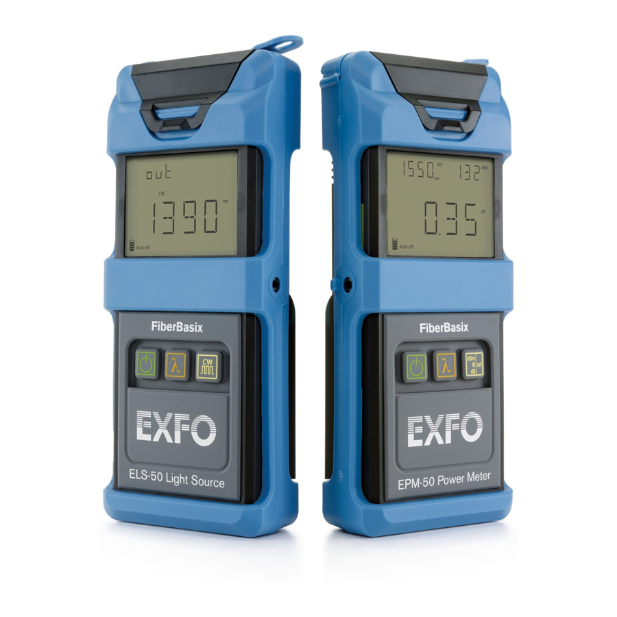
1 Introducing the EPM-50/ELS-50 This user guide covers the following products (unless otherwise specified, descriptions apply to all): EPM-50 Power Meter ELS-50 Light Source Main Features The EPM-50 Power Meter offers: a rugged design Interchangeable connector adapters 300 hours of battery life tone recognition for fiber identification a universal push-pull interface reference function for direct loss measurements... - Page 4 Introducing the EPM-50/ELS-50 Front View Protector Cap LCD display Keypad (EPM-50 shown) Back View Safety label and serial number Quick reference label Battery compartment (3 alkaline or rechargeable batteries) Connector port...
-
Page 5: Power Sources
Power Sources The units operate with 3 AA alkaline or rechargeable batteries. MPORTANT If the battery level becomes too low, the unit turns itself off. Typical Applications The units offer specific typical applications. EPM-50 Power Meter: High power model for CATV and Telcoapplications Enterprise/LAN for singlemode and multimode measurements ELS-50 Light Source: Telco/CATV and FTTH models;... -
Page 6: Safety Information
Safety Information 2 Safety Information ARNING Do not install or terminate fibers while a laser source is active. Never look directly into a live fiber and ensure that your eyes are protected at all times. ARNING Use of controls, adjustments and procedures for operation and maintenance other than those specified herein may result in hazardous radiation exposure. -
Page 7: Getting Started
3 Getting Started Turning the Unit On and Off When you turn off the EPM-50, it saves the current wavelength, unit and reference power. MPORTANT If you remove the batteries, the unit will turn off without saving the above values. If batteries are low, the unit will save the above values and turn off. -
Page 8: Activating Automatic Shutdown (Auto-Off)
Getting Started Activating Automatic Shutdown (Auto-Off) When auto-off is activated, the unit will turn off after 10 minutes of idle time. Auto-off is activated by default when you turn on the unit. To deactivate/reactivateauto-off: When unit is on, press Note: Auto-off is automatically disabled when you perform an offset nulling. -
Page 9: Cleaning And Connecting Optical Fibers
Cleaning and Connecting Optical Fibers MPORTANT To ensure maximum power and to avoid erroneous readings: Always clean fiber ends as explained below before inserting them into the port. FS is not responsible for damage or errors caused by bad fiber cleaning or handling. Ensure that your patchcord has appropriate connectors. -
Page 10: Measuring Power Or Loss (Epm-50)
Measuring Power or Loss (EPM-50) 4 Measuring Power or Loss (EPM-50) Nulling Electrical Offsets Temperature and humidity variations affect the performance of electronic circuits and optical detectors. Nulling the electrical offsets eliminates these effects. Your unit has been designed not to require offset nulling under normal operation, but you should perform it whenever environmental conditions change significantly or when measuring very low power values. -
Page 11: Referencing Your Power Meter To A Source
Referencing Your Power Meter to a Source In reference mode, your unit displays the loss created by the fiber under test only, since a reference value is subtracted from the measured power. Note: You must set a reference value separately for each wavelength. To reference the power meter to a sourcemanually: 1. -
Page 12: Measuring Power Or Loss
Measuring Power or Loss (EPM-50) Measuring Power or Loss Measuring absolute power is done the same way as referencing the power meter to a source, except for the referencing step. To perform power or lossmeasurements: If necessary, perform an offset nulling (see Nulling Electrical Offsets on page 2. - Page 13 5. Activate the source at the desired wavelength. Match the so urce and power meter wavelengths using Modulation detected Actual power When power or loss is outside power limits or loss Technical Specifications on page (see of fiber under test When the unit detects a modulated signal, it displays the modulation value and average measured power or loss (see left illustration above).
-
Page 14: Using A Light Source (Els-50)
Using a Light Source (ELS-50) 5 Using a Light Source (ELS-50) The ELS-50 may contain up to three sources. Activating/Deactivating a Light Source Only one source may be active at a time. When no source is active, the unit displays OFF and leaves the top left corner empty. -
Page 15: Maintenance
6 Maintenance This product contains no user-serviceable parts. However, it contains sensitive electronic and optical components, and should be handled carefully and stored in its carrying case when not in use. To help ensure long, trouble-free operation: Always inspect fiber-optic connectors before using them and clean them if necessary. -
Page 16: Cleaning Eui Connectors
Maintenance Cleaning EUI Connectors Regular cleaning of EUIconnectors will help maintain optimum performance. There is no need to disassemble the unit. MPORTANT If any damage occurs to internal connectors, the module casing will have to be opened and a new calibration will be required. To clean EUIconnectors: 1. - Page 17 5. Repeat steps 3 to 4 with a dry cleaning tip. Note: Make sure you don’t touch the soft end of the cleaning tip. 6. Clean the ferrule in the connector port as follows: 6a. Deposit one drop of isopropyl alcohol on a lint-free wiping cloth. MPORTANT Since isopropyl alcohol is not absolutely pure, it may leave residues if used abundantly or left to evaporate (about 10 seconds).
-
Page 18: Cleaning Fixed Connectors
Maintenance Cleaning Fixed Connectors Regular cleaning of connectors will help maintain optimum performance. Do not try to disassemble the unit. Doing so would break the connector. To clean fixed connectors: 1. Fold a lint-free wiping cloth in four to form a square. 2. -
Page 19: Cleaning Detector Ports
9. Continue to turn as you withdraw the cleaning tip. 10. Repeat steps 7 to 9, but this time with a dry cleaning tip. Make sure you don’t touch the soft end of the cleaning tip and verify the Note: cleanliness of the cotton tip. -
Page 20: Replacing Batteries
Maintenance Replacing Batteries Your unit requires three AA alkaline or rechargeable batteries. To replace batteries: Turn off the unit. 2. Open the battery compartment door located at the back of the unit. 3. Replace batteries, respecting the polarity as shown. 4. -
Page 21: Troubleshooting
Correctly place protective cap on LIGH Nulling is not performed. detector port, then retry. (EPM-50 only) 3/11 Embedded software problem. Contact EXFO. Hardware problem. Replace unit. Non-volatile memory corrupted Hold down all 3 buttons during (would occur during unit initialization to reset unit. initialization). - Page 22 A Technical Specifications MPORTANT The following technical specifications can change without notice. The information presented in this section is provided as a reference only. EPM-50 Specifications SPECIFICATIONS MODEL EPM-53 EPM-53X Power meter port InGaAs InGaAsX Power range (dBm) 1 0 to –6 0 2 6 to –5 0 Number of calibrated wavelengths Power uncertainty...
-
Page 23: Contacting The Technical Support Group
Technical Specifications ELS-50 Specifications SPECIFICATIONS MODEL 23BL Central wavelength (nm) 3 1 0 ± 2 0 8 5 0 ± 2 5 5 5 0 ± 2 0 3 0 0 + 5 0 / – 1 0 b, c Spectral width (nm) 4 0 /1 2 0 –2 4 /–2 1...
Need help?
Do you have a question about the EPM-50 Series and is the answer not in the manual?
Questions and answers