Table of Contents
Advertisement
Quick Links
Advertisement
Table of Contents

Related Manuals for EXFO IQS-12008


Summary of Contents for EXFO IQS-12008
- Page 1 User Guide IQS-12008 All-Band Component Analyzer...
- Page 2 Engineering Inc. (EXFO). Information provided by EXFO is believed to be accurate and reliable. However, no responsibility is assumed by EXFO for its use nor for any infringements of patents or other rights of third parties that may result from its use.
-
Page 3: Table Of Contents
Contents Contents Certification Information ......................v 1 Introducing the IQS-12008 All-Band Component Analyzer ......1 Main Features .........................1 Using COM and LabVIEW to Control the System ..............2 System Overview ........................3 Hardware Components Description ..................4 Testing Procedure Overview ....................8 Conventions ..........................9 2 Safety Information .................. - Page 4 Contacting the Technical Support Group ................103 Transportation ........................104 9 Warranty ....................105 General Information ......................105 Liability ..........................105 Exclusions ...........................106 Certification ........................106 Service and Repairs ......................107 EXFO Service Centers Worldwide ..................108 A Technical Specifications ................109 B Definitions and Calculation Methods ............111 Index .......................121 IQS-12008...
-
Page 5: Certification Information
F.C.C. Information Electronic test equipment is exempt from Part 15 compliance (FCC) in the United States. However, compliance verification tests are systematically performed on most EXFO equipment. Information Electronic test equipment is subject to the EMC Directive in the European Union. - Page 6 DECLARATION OF CONFORMITY Application of Council Directive(s): 73/23/EEC - The Low Voltage Directive 89/336/EEC - The EMC Directive And their amendments Manufacturer’s Name: EXFO Electro-Optical Engineering Inc. Manufacturer’s Address: 400 Godin Avenue Quebec, Quebec Canada, G1M 2K2 (418) 683-0211 Equipment Type/Environment: Test &...
- Page 7 DECLARATION OF CONFORMITY Application of Council Directive(s): 73/23/EEC - The Low Voltage Directive 89/336/EEC - The EMC Directive And their amendments Manufacturer’s Name: EXFO Electro-Optical Engineering Inc. Manufacturer’s Address: 400 Godin Avenue Quebec, Quebec Canada, G1M 2K2 (418) 683-0211 Equipment Type/Environment: Test &...
- Page 8 DECLARATION OF CONFORMITY Application of Council Directive(s): 73/23/EEC - The Low Voltage Directive 89/336/EEC - The EMC Directive And their amendments Manufacturer’s Name: EXFO Electro-Optical Engineering Inc. Manufacturer’s Address: 400 Godin Avenue Quebec, Quebec Canada, G1M 2K2 (418) 683-0211 Equipment Type/Environment: Test &...
-
Page 9: Introducing The Iqs-12008 All-Band Component Analyzer
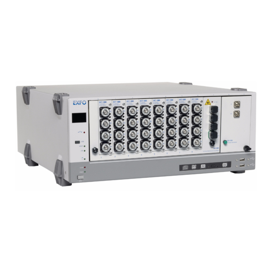
All-Band Component Analyzer Main Features The IQS-12008 All-Band Component Analyzer allows test in the O, E, S, C, L and U bands. This one-box system uses a tunable laser source covering the 1260 to 1630 nm range to provide IL, ORL and PDL measurements as a function of wavelength. -
Page 10: Using Com And Labview To Control The System
C:\Program Files\EXFO\ IQS12008\. LabVIEW demo program (with source code). The program is located in C:\Program Files\EXFO\LabVIEW Getting Started\. For more information on how to install and use EXFO LabVIEW drivers, refer to the IQS-500/600 user guide. IQS-12008... -
Page 11: System Overview
Introducing the IQS-12008 All-Band Component Analyzer System Overview System Overview The IQS-12008 All-Band Component Analyzer consists of a series of IQS modular test and measurement instruments that are completely integrated by the software application. The standard configuration includes IL and ORL measurements. Adding the IQS-5150B All-Band Polarization State Adjuster enables you to perform PDL measurements using the standardized Mueller-Matrix calculation. -
Page 12: Hardware Components Description
Introducing the IQS-12008 All-Band Component Analyzer Hardware Components Description Hardware Components Description Module or device Usage IQS-510P Controller Unit Houses the instruments required by the system. IQS-610P Controller Unit Controls the measurement process as well as data interpretation and storage. - Page 13 Introducing the IQS-12008 All-Band Component Analyzer Hardware Components Description All-Band Multichannel Loss Meter The IQS-9800 All-Band Multichannel Loss Meter is an eight-slot module that integrates all that is required to fully characterize IL and ORL of passive components: All-band tunable laser source...
- Page 14 Introducing the IQS-12008 All-Band Component Analyzer Hardware Components Description Four-Detector IQS Mini-Modules The Four-Detector IQS Mini-Module is a plug-in card that includes four high-speed, autoranging detection channels. These detectors provide low-polarization dependence for accurate PDL measurements. These modules are the key for system expansion. You can use up to 8 mini-modules in you system, depending on the number of channels you need (4 to 32).
- Page 15 Introducing the IQS-12008 All-Band Component Analyzer Hardware Components Description All-Band Polarization State Adjuster (Optional) The IQS-5150B All-Band Polarization State Adjuster is required for spectral PDL characterization of passive components with the All-Band Component Analyzer. The module uses two slots of the IQS-510P/610P Controller Unit.
-
Page 16: Testing Procedure Overview
Introducing the IQS-12008 All-Band Component Analyzer Testing Procedure Overview Testing Procedure Overview With the specified test configuration, the application controls the different IQS modules to characterize a device under test (DUT). Once your configuration is complete, a typical test sequence to perform IL,... -
Page 17: Conventions
Introducing the IQS-12008 All-Band Component Analyzer Conventions Conventions Before using the product described in this manual, you should understand the following conventions: ARNING Indicates a potentially hazardous situation which, if not avoided, could result in death or serious injury. Do not proceed unless you understand and meet the required conditions. -
Page 19: Safety Information
Safety Information ARNING Do not install or terminate fibers while a light source is active. Never look directly into a live fiber and ensure that your eyes are protected at all times. ARNING Use of controls, adjustments and procedures for operation and maintenance other than those specified herein may result in hazardous radiation exposure. -
Page 21: Getting Started With Your All-Band Component Analyzer
Getting Started with Your All-Band Component Analyzer Inserting and Removing Test Modules AUTION Never insert or remove a module while the controller unit and its expansion units are turned on. This will result in immediate and irreparable damage to both the module and unit. To insert a module into the controller or expansion unit: 1. - Page 22 6. While applying slight pressure to the module, turn the retaining screw knob (located at the bottom of the panel) clockwise until the knob is horizontal. This will secure the module into its “seated” position. IQS-12008...
- Page 23 Note: You can insert IQ modules into your controller or expansion unit; the IQS Manager software will recognize them. However, the IQS-12008 locking mechanism (retaining screw) will not work for IQ modules. To remove a module from your controller or expansion unit: 1.
- Page 24 3a. Slide the top of the protective cover into the upper grooves of the unit. 3b. Snap the cover into place by pushing the retaining screw knob. AUTION Failure to reinstall protective covers over empty slots will result in ventilation problems. IQS-12008...
-
Page 25: Inserting And Removing The All-Band Multichannel Loss Meter
Getting Started with Your All-Band Component Analyzer Inserting and Removing the All-Band Multichannel Loss Meter Inserting and Removing the All-Band Multichannel Loss Meter You must insert the All-Band Multichannel Loss Meter into the eight first slots of the controller unit. Otherwise, you will not be able to use the provided patchcord. -
Page 26: Inserting And Removing Detector Cards
4. Push the card all the way to the back of the slot, until the front panel is flush with the module’s front plate. 5. Replace the top and bottom screws to retain the card in place. 6. Exit and restart the application so that the system recognizes the DET-1843 detector card. IQS-12008... -
Page 27: Installing Hardware Components
Getting Started with Your All-Band Component Analyzer Installing Hardware Components To remove a detector card: 1. Remove the top and bottom screws that retain the card in place. 2. Hold the card by the FOAs and pull it out gently. 3. - Page 28 Connect the output of the IQS-5150B to the input (laser input port) of the IQS-9800 using the semi-rigid patchcord provided with the system. ACTIVE Laser Output Laser Input Ref. (To DUT) IQS-5150B All-Band Polarization State Adjuster IQS-9800 All-Band Multichannel Loss Meter IQS-12008...
- Page 29 Getting Started with Your All-Band Component Analyzer Installing Hardware Components Configuration without PDL (IQS-5150B) Connect the laser output of the IQS-9800 to the laser input of the same module with the provided polarization-maintaining patchcord, as illustrated below. ACTIVE Laser Output Laser Input Ref.
-
Page 30: Installing The Iqs-12008 All-Band Component Analyzer Software
Getting Started with Your All-Band Component Analyzer Installing the IQS-12008 All-Band Component Analyzer Software Installing the IQS-12008 All-Band Component Analyzer Software For the All-Band Component Analyzer to function properly, IQS Manager must be installed on your IQS platform. Normally, you would not have to install IQS Manager or the All-Band Component Analyzer application, except in particular circumstances (such as after having reinstalled Microsoft Windows). -
Page 31: Starting And Exiting The All-Band Component Analyzer Application
Analyzer Application To start the All-Band Component Analyzer application: On the Windows taskbar, click the Start button, select Programs > EXFO > IQS-12008 > IQS-12008 All-Band Component Analyzer. Double-click the IQS-12008 All-Band Component Analyzer desktop icon. To exit the All-Band Component Analyzer application: Select Exit from the File menu. -
Page 33: Setting Up The All-Band Component Analyzer
It is particularly important before performing any calibration, reference, or null measurement. The initialization can be either automatically performed when the IQS-12008 All-Band Component Analyzer application is started, or performed manually afterwards. Once the initialization is completed, the laser is positionned at its highest wavelength, where almost no power is emitted. - Page 34 3. In the System Settings window, select Auto-initialization. 4. Click OK to confirm your choice. 5. Let the system warm-up for 30 minutes. The system will automatically initialize each time the IQS-12008 application is started. To initialize the system manually: 1.
-
Page 35: Nulling Electrical Offsets
Temperature and humidity variations affect the performance of electronic circuits and optical detectors, which can offset measurement results. To compensate for this offset, the IQS-12008 is equipped with an offset nulling function. EXFO recommends performing a nulling of the electrical offsets whenever environmental conditions change. - Page 36 To avoid disconnecting test jumpers from the laser input port for the nulling, select the check box. Note: You can also perform a nulling without putting caps on detectors if there are connectors on all detectors. 4. Press Start to begin the nulling process. IQS-12008...
-
Page 37: Calibrating The System
Setting Up the All-Band Component Analyzer Calibrating the System Calibrating the System Although the system has been calibrated at the factory, it must be calibrated again upon installation. Calibration includes: Detector Response calibration: To correct variations in sensitivity and response of the different detectors. Return Loss (ORL) calibration (14.7 dB reflection and Zero). - Page 38 You must perform a detector response calibration in the following cases: You replace the loss meter. You add detector cards to the system or replace them. You replace the IQS-5150B All-Band Polarization State Adjuster (PSA). You add a PSA to the system. IQS-12008...
- Page 39 Setting Up the All-Band Component Analyzer Calibrating the System To perform the detector response calibration: 1. Connect as shown, depending on the setup you intend to use. ACTIVE Laser Output Polarization- maintaining Laser Input patchcord Ref. (To DUT) IQS-9800 All-Band Multichannel Loss Meter Test setup Master test jumper without PDL...
- Page 40 8. Click Next to perform the measurement and move on to the next detector. 9. Following the instructions on the screen, connect the output port to all remaining channels in the system. 10. When the detector response measurement is complete, click Finish and close the wizard. IQS-12008...
-
Page 41: Validating Calibration Measurement Quality
The averaged difference should not be greater than a set value within a determined tolerance. The detector response can be configured prior to calibrating the IQS-12008 All-Band Component Analyzer. To change the detector response settings: 1. - Page 42 It will be necessary to repeat the return loss calibration if any of the modules are replaced. One way of verifying the ORL measurement is to measure the ORL of the reflection reference test jumper at 1550 nm. The result should be 14.7 dB ± the uncertainty indicated in the specification sheet. IQS-12008...
- Page 43 Setting Up the All-Band Component Analyzer Validating Calibration Measurement Quality To perform the return loss calibration: 1. Connect as shown, depending on the setup you intend to use. ACTIVE Laser Output Polarization- maintaining Laser Input patchcord Ref. (To DUT) IQS-9800 All-Band Multichannel Loss Meter Test setup without PDL...
- Page 44 7. Then, for the zero calibration, mandrel wrap the reflection reference jumper, giving the fiber 10 turns around the mandrel tool. 8. Hold the fiber on the mandrel and click Next to proceed. 9. Click Finish when the return loss calibration has been done. IQS-12008...
-
Page 45: Referencing The System
System referencing comprises: Insertion loss (IL) reference IL/PDL reference Return loss (ORL) reference EXFO recommends that you perform reference measurements in the following cases: Every time you turn the system on. When you remove or replace the master test jumper. - Page 46 This may be useful if you want to perform high-isolation measurements. MPORTANT Before performing any reference measurement, ensure that all the connectors and fiber-optic adapters (FOAs) are clean, and that the warmup period (at least 30 minutes) is over. IQS-12008...
- Page 47 Setting Up the All-Band Component Analyzer Referencing the System To perform an insertion loss reference measurement: 1. Connect as shown, depending on the setup you intend to use. ACTIVE Laser Output Polarization- maintaining Laser Input patchcord Ref. (To DUT) IQS-9800 All-Band Multichannel Loss Meter Test setup Master test jumper...
- Page 48 From the References tab, select the Reference Averaging box. 4. Start the insertion loss reference procedure: On the menu bar, select Measurements > Reference > Insertion Loss From the References tab, select Insertion Loss and click the Start Reference button. IQS-12008...
- Page 49 Setting Up the All-Band Component Analyzer Referencing the System 5. At the bottom of the wizard screen, click Perform IL Reference to proceed or Cancel to stop. When the IL reference measurement scan is over, the word Done will appear to the right of the Insertion Loss reference option in the References tab, indicating that the reference has been successfully completed.
- Page 50 IL reference procedure is normal, especially if the DUT is very sensitive to polarization state changes. MPORTANT Before performing any reference measurement, ensure that all the connectors and fiber-optic adapters (FOAs) are clean, and that the warmup period (at least 30 minutes) is over. IQS-12008...
- Page 51 Setting Up the All-Band Component Analyzer Referencing the System To perform the IL/PDL reference measurement: 1. Connect as shown. Polarization-maintaining patchord ACTIVE Laser Output Laser Input Ref. (To DUT) IQS-5150B All-Band Polarization State Adjuster IQS-9800 All-Band Multichannel Loss Meter Master test jumper Rigid patchcord (provided with the system) 2.
- Page 52 The indicator Done means that the system has access to a reference file. If the environmental conditions change or if you use a different master test jumper, the reference values might not be valid for the tests to perform. IQS-12008...
- Page 53 Setting Up the All-Band Component Analyzer Referencing the System Return Loss Reference This reference provides a zero-reflection reference to the detector. The reference will be used to compensate for internal detector parasitic reflections and those coming from the connection with the master test jumper used for ORL measurement.
- Page 54 Master test jumper without PDL Polarization-maintaining patchord ACTIVE Laser Output Laser Input Ref. (To DUT) IQS-5150B All-Band Polarization State Adjuster IQS-9800 All-Band Multichannel Loss Meter Semi-rigid patchcord (provided with the system) Mandrel Master test jumper Test setup with PDL IQS-12008...
- Page 55 Setting Up the All-Band Component Analyzer Referencing the System 2. If you want to perform reference averaging (for a better signal-to-noise ratio): On the menu bar, select Measurement > Reference > Reference Averaging From the References tab, select the Reference Averaging box. 3.
-
Page 56: Configuring Test Parameters
Defining a smaller range optimizes the test results and may reduce testing time. The software allows to scan from 1250 to 1650 nm while the source emission is guaranteed on a slightly smaller range. IQS-12008... - Page 57 Setting Up the All-Band Component Analyzer Configuring Test Parameters Sampling resolution: Scan resolution (in pm). Offset compensation: Relationship between the motor position and the signal wavelength used in calculations to take into account any possible drift. Offset compensation is done using the internal wavelength referencing elements (Fabry-Perot etalon and acetylene cell).
- Page 58 Compute PDCW/PDBW (PDL acquisition required): When testing for PDL, you may select to analyze the polarization-dependent central wavelength and the polarization-dependent bandwidth. For a definition of these parameters, refer to Bandpass Filters on page 112. IQS-12008...
- Page 59 Setting Up the All-Band Component Analyzer Configuring Test Parameters The application allows you to indicate the test selection in the Acquisition group. MPORTANT To ensure the best possible results, you should not perform ORL measurement at the same time than IL or PDL measurements when the DUT’s output ports are either terminated or mandrel-wrapped.
- Page 60 2. From the Analysis Parameters tab, enter the desired values in the corresponding boxes. Those values will be kept until you click Factory Settings to reset them. Note: You can save the measurements settings (File Menu > Save) for further use (File Menu > Recall). IQS-12008...
- Page 61 Setting Up the All-Band Component Analyzer Configuring Test Parameters Defining Pass/Fail Criteria for Bandpass DUTs You can specify pass/fail criteria for the DUT to determine whether or not the DUT is within specifications. The pass/fail criteria are divided into two groups: Bandpass Criteria: The bandpass criteria is always taken into account when testing a bandpass filter.
- Page 62 (lowest acceptable ORL) value at the corresponding ITU center wavelength. The default value is 50 dB. Maximum ripple at ITU CW ± bandpass: Ripple is the IL variation over the ITU defined bandpass interval of the channel. The default value is 0.5 dB. IQS-12008...
- Page 63 Setting Up the All-Band Component Analyzer Configuring Test Parameters To define the pass/fail criteria: 1. On the menu bar, select Measurements > Modify Measurement Settings. On the Measurement Settings tab, click the Modify button. 2. Select the Pass/Fail Criteria tab. 3.
- Page 64 (1260-1630 nm, 1290-1310 nm, 1400-1600 nm, 1500-1550 nm) be limited to one number (1590-1590 nm) To set the wavelength ranges: 1. On the menu bar, select Measurements > Modify Measurement Settings. On the Measurement Settings tab, click the Modify button. 2. Select the Analysis Results tab. IQS-12008...
- Page 65 Setting Up the All-Band Component Analyzer Configuring Test Parameters 3. Select which ranges you want to enable by checking the corresponding boxes. 4. Enter the minimum and maximum values for the selected wavelength ranges. If you enter the same value for maximum and minimum, only one measurement will be taken at that one wavelength instead of a range.
- Page 66 To change the channel names: 1. On the menu bar, select Measurements > Modify Measurement Settings. 2. Select the Chanel Names tab. IQS-12008...
- Page 67 Setting Up the All-Band Component Analyzer Configuring Test Parameters 3. Name the channels. To use the automatic naming feature, enter a generic name in the corresponding box, then click Generate. If you leave the box empty, the channels will only be identified by their numbers. To name channels manually, select one from the list to the left, type in the name you want under New channel name, then click Replace.
- Page 68 On the Measurement Settings tab, click the Modify button. 2. From the Analysis Parameters tab, change the atmospheric pressure value in the correspondig box. This value will be kept until you click Factory Settings to reset them. 3. Click OK to confirm your change. IQS-12008...
- Page 69 Setting Up the All-Band Component Analyzer Configuring Test Parameters Saving and Retrieving Measurement Settings Once all measurement settings have been configured, you can save them for future use, especially if these parameters will be used often. To save the measurement settings: 1.
- Page 70 1. Close the IQS-12008 application. 2. Go to C:\Program Files\EXFO\ IQS12008\Application12008.exe.config. MPORTANT Before modifying the configuration file, EXFO suggests that you make a copy of the Application12008.exe.config file. In case of problems, you could use this copy as a backup.
- Page 71 ITU grid baseline value. 5. Save the file and close the text editor. The changes will apply the next time you open the IQS-12008 All-Band Component Analyzer application. All-Band Component Analyzer...
-
Page 72: Optimizing Performance
30-minute warmup period and the specified operating environment (see Technical Specifications on page 109). The system is calibrated at EXFO and verified with a NIST SRM 2519 HCN absorption cell. You can use the offset compensation function to optimize test results. - Page 73 Setting Up the All-Band Component Analyzer Optimizing Performance IL/PDL Errors There are numerous possible sources of errors for the IL measurement. Some of them are inherent to system and test procedures, while others are related to operation and fiber handling. Understanding these sources of error will help you to optimize the accuracy of your loss measurements.
- Page 74 IL of the output connector or of the reference test jumper connector. This difference contributes directly to the ORL measurement error. For this reason, it is important to use a master test jumper with a good quality connector. IQS-12008...
-
Page 75: Testing Duts With The All-Band Component Analyzer
To ensure maximum power and to avoid erroneous readings: Always clean fiber ends as explained below before inserting them into the port. EXFO is not responsible for damage or errors caused by bad fiber cleaning or handling. Ensure that your patchcord has appropriate connectors. Joining mismatched connectors will damage the ferrules. -
Page 76: Performing Test Scans
The system will sweep the source, transfer the data, analyze the acquisition points, and display the results in accordance with the parameters displayed in the Analysis Parameters and Pass/Fail Criteria tabs. To configure these settings, see Configuring Test Parameters on page 48. IQS-12008... - Page 77 Testing DUTs with the All-Band Component Analyzer Performing Test Scans To perform a test scan: 1. From the Measurement Settings tab, select the desired tests. 2. Connect the DUT as shown, depending on the setup you intend to use. ACTIVE Laser Output Laser...
-
Page 78: Controlling Modules Individually
1. Select the Individual Module Control function tab, then Dectectors tab. 2. Select the detectors you wish to monitor by clicking the Select Detectors button and selecting the desired channels on the dialog box. Click OK to confirm and close the window. IQS-12008... - Page 79 Testing DUTs with the All-Band Component Analyzer Controlling Modules Individually 3. In the Tunable Laser Source group, you may set the laser source to a specific wavelength in three different ways: By sliding the cursor underneath the wavelength display. By clicking Wavelength and entering the desired wavelength. By clicking the left and right arrows located on each side of the wavelength cursor line.
- Page 80 8. Click Start. The Relative power and Internal ref. meter values are updated twice every second. 9. Click Stop once you are done. Note: If the continuous monitoring feature is enabled, the values in the Detectors tab will be disabled. IQS-12008...
-
Page 81: Viewing The All-Band Component Analyzer Results
Viewing the All-Band Component Analyzer Results Test results are available in two formats: a graph and a data table. The results can be viewed and analyzed on-screen or saved to a file for further analysis and printing. The following sections will present how to use the on-screen tools for results analysis and how to treat the data file for analysis using a spreadsheet application. - Page 82 5. Release both the mouse button and the SHIFT key. The area should be enlarged on the screen. 6. Repeat this procedure for further zoom levels. 7. Zoom out by clicking the zoom out or the best fit buttons. IQS-12008...
- Page 83 Viewing the All-Band Component Analyzer Results Viewing the Results Graph To return to the previous zoom level: 1. Click once in the plot area. 2. Hold down the CTRL or the SHIFT key. 3. Click the right mouse button. To pan the graph: 1.
- Page 84 You can display IL, IL/PDL, and ORL traces individually or all at the same time on the graph. To show or hide a trace: Click the button corresponding to the desired trace. PDL values IL and ORL axis values axis Wavelength values axis IQS-12008...
- Page 85 Viewing the All-Band Component Analyzer Results Viewing the Results Graph To select which traces to display by default: 1. Select the Plots tab. 2. Select the channel or channels to display. Additional information is provided as to the channel’s name, the color used to display the graph, as well as the channel’s associated number and card.
- Page 86 Wavelength range end marker The markers are crossbars that travel along the IL trace. The vertical bars travel along the wavelength axis, while the horizontal bars select automatically the power level at the intersection between the two bars. IQS-12008...
- Page 87 Viewing the All-Band Component Analyzer Results Viewing the Results Graph To view markers on the graph: 1. Select the Markers tab to access markers functions. 2. Select the Display Markers box. 3. Attach markers A and B to a detector from the Attach to box. 4.
-
Page 88: Viewing The Results Tables
This will happen for the adjacent value (directly before or after the channel) and non-adjacent value (not directly before or after the channel). The data presented in these tables is calculated in accordance with the definitions presented in Definitions and Calculation Methods on page 111. IQS-12008... - Page 89 Viewing the All-Band Component Analyzer Results Viewing the Results Tables To view the results tables: 1. From the Measurements function tab, select the Results tab. 2. Select the desired pane. All-Band Component Analyzer...
-
Page 90: Exporting Data
2. In the Export Graph window, enter the desired file name. 3. Select the desired file name format. 4. Click Save. By default, the file will be saved to the My Documents folder. Open an image editor or import the graph into a word processor to view the file. IQS-12008... - Page 91 Viewing the All-Band Component Analyzer Results Exporting Data To set up the automatic exportation settings: 1. In the Edit menu, select Export Results Settings. 2. In the Export results settings dialog box, check the Automatic Export box. The prefix is the part of the name that will not change. It will accept up to 30 characters The suffix is made of three digits from 00 to 999.
- Page 92 4. Click Save. By default, the file will be saved to the My Documents folder. 5. Open a spreadsheet, text editor or word processor to view the file. The columns (fields) are separated using a tab or a comma. Tab-separated text file IQS-12008...
-
Page 93: Maintenance
Maintenance To help ensure long, trouble-free operation: Always clean fiber-optic connectors before using them. Keep the unit free of dust. Clean the unit casing and front panel with a cloth slightly dampened with water. Store unit at room temperature in a clean and dry area. Keep the unit out of direct sunlight. -
Page 94: Cleaning Eui Connectors
3. Slowly insert the cleaning tip into the EUI adapter until it comes out on the other side (a slow clockwise rotating movement may help). 4. Gently turn the cleaning tip one full turn, then continue to turn as you withdraw it. IQS-12008... - Page 95 6c. With a dry lint-free wiping cloth, gently wipe the same surfaces to ensure that the connector and ferrule are perfectly dry. 6d. Verify connector surface with a portable fiber-optic microscope (for example, EXFO’s FOMS) or inspection probe (for example, EXFO’s FIP). ARNING Verifying the surface of the connector WHILE THE UNIT IS ACTIVE WILL result in permanent eye damage.
-
Page 96: Cleaning Detector Ports
4. While applying light pressure (to avoid breaking the detector window), gently rotate the cleaning tip on the detector window. 5. Repeat step 4 with a dry cleaning tip or blow dry with compressed air. 6. Discard the cleaning tips after one use. IQS-12008... -
Page 97: Recalibrating The Unit
You should determine the adequate calibration interval for your unit according to your accuracy requirements. Under normal use, EXFO recommends calibrating your unit every three years. All-Band Component Analyzer... -
Page 98: Recycling And Disposal (Applies To European Union Only)
This equipment was sold after August 13, 2005 (as identified by the black rectangle). Unless otherwise noted in a separate agreement between EXFO and a customer, distributor or commercial partner, EXFO will cover costs related to the collection, treatment, recovery and disposal of... -
Page 99: Troubleshooting
3. Go to C:\Documents and Setting\All Users\Application Data\EXFO\IQS-12008 and delete the Reference.cfg and Calibration.cfg files. 4. Start the IQS-12008 All-Band Component Analyzer application. 5. From the Measurement menu, select System Settings. Depending on if your test setup includes PDL or not, select or clear the IQS-5150B box. - Page 100 10. When nulling is complete, connect as shown, depending on the setup you intend to use. ACTIVE Laser Output Polarization- maintaining Laser Input patchcord Ref. (To DUT) IQS-9800 All-Band Multichannel Loss Meter Test setup Master test jumper without PDL IQS-12008...
- Page 101 Troubleshooting Ensuring Proper Hardware Operation Polarization-maintaining patchord ACTIVE Laser Output Laser Input Ref. (To DUT) IQS-5150B All-Band Polarization State Adjuster IQS-9800 All-Band Multichannel Loss Meter Semi-rigid patchcord Test setup Master test jumper with PDL (provided with the system) 11. On the menu bar, select Measurement >Calibration> Calibration Averaging.
- Page 102 Referencing the System on page 37. 14. Set the analysis parameters as follows: 14a.On the menu bar, select Measurement > Modify Measurement Settings. 14b.From the Analysis Parameters tab, enter the values in the corresponding boxes, as shown: 14c. Click OK to confirm. IQS-12008...
- Page 103 Troubleshooting Ensuring Proper Hardware Operation 15. If your test setup includes a PSA, go directly to step 16. If you are testing without a PSA, perform an IL measurement by connecting, the master test jumper to each detector, one at a time. Click Start Acquisition to start the measurement.
- Page 104 FOA of the channels having incorrect curves or noise level. Bad nulling (light reached detectors) or nulling was performed too long ago. FOAs installed on the channels having incorrect curves or noise level are dirty. Equipment is defective. IQS-12008...
- Page 105 Troubleshooting Ensuring Proper Hardware Operation 16. Measure the IL dynamic range as follows: 16a.Put protective caps on all detectors. 16b.Perform an IL measurement on all channels (select IL option and not IL/PDL) with the averaging option selected. For more information, see Configuring Test Parameters on page 48 and Performing Test Scans on page 68.
- Page 106 Bad nulling (light reached detectors) or nulling was performed too long ago. During detector response, patchcord was not properly connected to the FOA of the channels having a low dynamic range. FOAs installed on the channels having a low dynamic range are dirty. Equipment is defective. IQS-12008...
- Page 107 Troubleshooting Ensuring Proper Hardware Operation 17. On the menu bar, select Measurement > Calibration > Return Loss to perform a return loss calibration. Ensure that the averaging option is selected. For more information, see Return Loss Calibration on page 34. To ensure a better accuracy, keep the fiber mandrel-wrapped between calibration and reference steps.
- Page 108 ORL calibration or reference. Master test jumper is defective. Equipment is defective. 20. If your test setup includes a PSA, on the menu bar, select Measurements > Reference > IL/PDL to perform a PDL reference. Ensure that the averaging option is selected. IQS-12008...
- Page 109 Troubleshooting Ensuring Proper Hardware Operation 21. If your test setup includes a PSA, perform an IL/PDL measurement on all channels. For more information, see Performing Test Scans on page 68. The bottom of the resulting PDL curves must be at 0 dB with a typical noise of +0.025.
- Page 110 Master test jumper was not properly connected to the Ref. Out port during reference. FOA installed on the first channel of the leftmost DET-1843 card is dirty. All FOAs are dirty. Equipment is defective. From the Help menu, select IQS-12008 All-Band Component Analyzer Help. IQS-12008...
-
Page 111: Contacting The Technical Support Group
Contacting the Technical Support Group To obtain after-sales service or technical support for this product, contact EXFO at one of the following numbers. The Technical Support Group is available to take your calls from Monday to Friday, 8:00 a.m. to 7:00 p.m. -
Page 112: Transportation
Pack the unit in its original packing material when shipping. Avoid high humidity or large temperature fluctuations. Keep the unit out of direct sunlight. Avoid unnecessary shocks and vibrations. IQS-12008... -
Page 113: Warranty
SPECIAL, INCIDENTAL, OR CONSEQUENTIAL DAMAGES. Liability EXFO shall not be liable for damages resulting from the use of the product, nor shall be responsible for any failure in the performance of other items to which the product is connected or the operation of any system of which the product may be a part. -
Page 114: Exclusions
Warranty Exclusions Exclusions EXFO reserves the right to make changes in the design or construction of any of its products at any time without incurring obligation to make any changes whatsoever on units purchased. Accessories, including but not limited to fuses, pilot lamps, batteries and universal interfaces (EUI) used with EXFO products are not covered by this warranty. -
Page 115: Service And Repairs
5. Return the equipment, prepaid, to the address given to you by support personnel. Be sure to write the RMA number on the shipping slip. EXFO will refuse and return any package that does not bear an RMAnumber. -
Page 116: Exfo Service Centers Worldwide
Warranty EXFO Service Centers Worldwide EXFO Service Centers Worldwide If your product requires servicing, contact your nearest authorized service center. EXFO Headquarters Service Center 400 Godin Avenue 1 866 683-0155 (USA and Canada) Quebec (Quebec) G1M 2K2 Tel.: 1 418 683-5498... -
Page 117: A Technical Specifications
The following technical specifications can change without notice. The information presented in this section is provided as a reference only. To obtain this product’s most recent technical specifications, visit the EXFO Web site at www.exfo.com. Source Value Wavelength range (nm) 1260 –... - Page 118 Size (H x W x D) 116 mm x 30 mm x 131 mm in x 1 in x 5 Weight 0.12 kg 0.26 lb IQS-12008 system Temperature operating 10 °C to 40 °C 50 °F to 104 °F storage –20 °C to 50 °C –4 °F to 122 °F...
-
Page 119: B Definitions And Calculation Methods
Definitions and Calculation Methods The IQS-12008 All-Band Component Analyzer performs measurements and uses them in automated calculations. The definitions and calculation methods used are explained in this chapter. The All-Band Component Analyzer recognizes the following DUT types: Bandpass or Notch... - Page 120 Ripple at ITU ±x nm Maximum IL variations across bandpass defined as ITU CW ±x nm (see Ripple (dB) on page 116). Isolation Smallest difference between in-band (BW1) loss and other channel band (BW1) loss (see Channel Isolation (dB) on page 117). IQS-12008...
- Page 121 Definitions and Calculation Methods Bandwidth (nm) Bandwidth is the spectral width over which the attenuation of the device exceeds some stated loss value. The system can measure bandwidth at three different attenuation levels, called BW1, BW2, and BW3, relative to the minimum attenuation level, as illustrated in the following diagram.
- Page 122 In this method, you specify the wavelength range to use for the evaluation. You will have to provide a span range centered around the ITU CWDM central wavelength. As shown in the diagrams, the wavelength range for BW1 and ITU bandpass is different and the resulting calculations will be different. IQS-12008...
- Page 123 Definitions and Calculation Methods Central Wavelength (nm) The central wavelength is the wavelength at the midpoint between the lower and upper wavelengths at BW1 dB level from the peak. Note that the central wavelength is not necessarily the peak wavelength. 0 dB loss line 3 dB Increasing loss...
- Page 124 Definitions and Calculation Methods Ripple (dB) The ripple is the IL variation over the ITU defined bandpass of each channel. +Δλ Ripple Δλ – ITU bandpass IQS-12008...
- Page 125 Definitions and Calculation Methods Channel Isolation (dB) ITU (N) ITU (N–1) (dB) in ITU (N) Main Interfering bandpass channel channel Isolation (dB) from interfering channel (dB) ITU (N–1) bandpass ITU bandpass (N–1) ITU bandpass (N) The application calculates the worst-case isolation, which is the smallest difference in IL between two intervals on the main channel curve (BW1 and BW1...
- Page 126 The wavelengths that segregate these regions are determined in a function that will find the nominal attenuation for each of the left and right shoulders. This is a statistical calculation and can be different for the right and left shoulders. IQS-12008...
- Page 127 Definitions and Calculation Methods Undefined Filters IL, PDL and ORL values are given at 1310 nm, 1490 nm, 1550 nm and 1625 nm. Undefined Filters Maximum attenuation over the entire range. Maximum PDL based on the entire analysis range. ORL value representing the strongest reflection. All-Band Component Analyzer...
-
Page 129: Index
Index Index cleaning detector ports ........88 after-sales service ........103 EUI connectors ........86 all-band multichannel loss meter ....5 fiber ends..........67 all-band polarization state adjuster....7 front panel..........85 application, starting ........23 UI connectors......... 86 averaging components calibration .......... - Page 130 ........85 insertion loss ..........115 fusion splices..........65 installing hardware ..........19 IQS-12008 software ....... 22 IQS-510E expansion unit ....... 4 graph markers..........78 IQS-510P controller unit ........ 4 IQS-5150B polarization state adjuster ... 4 IQS-610E Expansion Units......4 hardware IQS-610P controller unit ........
- Page 131 64 service and repairs ........107 performing null measurement..... 27 service centers ........... 108 polarization state adjuster......4, 7 shipping to EXFO........107 polarization states........42 software, installing ........22 preparing hardware ........25 source............20 specifications, product ......109 standard configuration........
- Page 132 UI connectors, cleaning....... 86 undefined filters........119 unit recalibration......... 89 viewing results graph ........73 warmup period ....... 25, 64, 65 warranty............ 105 certification ......... 106 exclusions ..........106 general ..........105 liability..........105 wavelength central ..........115 reference ..........20 IQS-12008...
- Page 133 EXFO ASIA-PACIFIC 151 Chin Swee Road SINGAPORE 169876 #03-29, Manhattan House Tel.: +65 6333 8241 · Fax: +65 6333 8242 TOLL-FREE (USA and Canada) 1 800 663-3936 © 2008 EXFO Electro-Optical Engineering Inc. All rights reserved. Printed in Canada (2008-05)
Need help?
Do you have a question about the IQS-12008 and is the answer not in the manual?
Questions and answers