
Related Manuals for EXFO IQS-5320-EI


Summary of Contents for EXFO IQS-5320-EI
- Page 1 (217) 352-9330 | Click HERE Find the Exfo IQS-5320-EI at our website:...
- Page 2 Multi-Wavelength Meter IQS-5320 User Guide If the equipment described herein bears the symbol, the said equipment complies with the P/N: 1035496 applicable European Union June 2002 Directive and Standards mentioned in the Declaration of Conformity. Artisan Technology Group - Quality Instrumentation ... Guaranteed | (888) 88-SOURCE | www.artisantg.com...
- Page 3 Engineering Inc. (EXFO). Information provided by EXFO is believed to be accurate and reliable. However, no responsibility is assumed by EXFO for its use nor for any infringements of patents or other rights of third parties that may result from its use.
-
Page 4: Table Of Contents
5 Preparing Your Multi-Wavelength Meter for a Test ........45 Nulling Electrical Offsets .......................45 Connecting Optical Fibers .....................46 Installing the EXFO Universal Interface (EUI) .................47 Selecting a Test Control Mode ....................48 Multi-Wavelength Meter Artisan Technology Group - Quality Instrumentation ... Guaranteed | (888) 88-SOURCE | www.artisantg.com... - Page 5 Contents 6 Taking Measurements in WDM Mode ............49 Performing WDM Mode Measurements ................50 Selecting a Graph Type in WDM Mode .................52 Viewing WDM Mode Measurement Results ................54 Viewing Trace Information ....................56 Viewing Detailed Trace Measurements .................57 Adjusting Trace Display Resolution ..................59 7 Taking Measurements in Drift Mode ............61 Performing Drift Mode Measurements .................61 Selecting a Graph Type in Drift Mode ...................63...
- Page 6 Contents 11 Troubleshooting ..................101 Viewing Online Documentation ..................101 Finding Information on the EXFO Web Site ................101 Contacting the Technical Support Group ................102 Transportation ........................103 12 Warranty ....................105 General Information ......................105 Liability ..........................106 Exclusions ...........................106 Certification ........................106 Service and Repairs ......................107 EXFO Service Centers Worldwide ..................108...
-
Page 7: Certification Information
This unit has undergone extensive testing according to the European Union Directive and Standards. All pre-qualification tests were performed internally, at EXFO, while all final tests were performed externally, at an independent, accredited laboratory. This guarantees the unerring objectivity and authoritative compliance of all test results. - Page 8 Certification Information DECLARATION OF CONFORMITY Electro-Optical Engineering Application of Council Directive(s): 73/23/EEC - The Low Voltage Directive 89/336/EEC - The EMC Directive Manufacturer’s Name: EXFO ELECTRO-OPTICAL ENG. Manufacturer’s Address: 465 Godin Avenue Vanier, Quebec Canada G1M 3G7 (418) 683-0211 Equipment Type/Environment: Industrial Scientific Equipment Trade Name/Model No.:...
- Page 9 Artisan Technology Group - Quality Instrumentation ... Guaranteed | (888) 88-SOURCE | www.artisantg.com...
-
Page 10: Introducing The Iqs-5320 Multi-Wavelength Meter
Introducing the IQS-5320 Multi-Wavelength Meter Wavelength-division multiplexing (WDM) plays a dominant role in the telecommunications industry. Using multiple data streams over separate channels on the same fiber has created a need for new test procedures and equipment. In fact, WDM had added another dimension to existing test procedures, but in addition to time and power, we now need to be concerned with wavelength. -
Page 11: Typical Applications
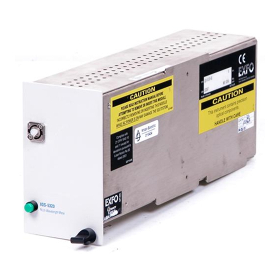
Introducing the IQS-5320 Multi-Wavelength Meter Typical Applications Detector port IQS-5320 LED push button Multi-Wavelength Meter Retaining screw knob Typical Applications By allowing you to perform laser diode spectral characterization, the MWM is ideal for controlling the drift of DWDM sources in transmission system qualification and reliability testing. -
Page 12: Mwm Measurement Principle
Introducing the IQS-5320 Multi-Wavelength Meter MWM Measurement Principle MWM Measurement Principle The MWM generates results that are similar, but complementary, to those of the optical spectrum analyzer (OSA). As with the OSA, the results are displayed as power versus wavelength. However, despite the similarity to the OSA, the technology used to achieve results in the MWM is fundamentally different: the OSA uses diffraction grating, whereas the MWM uses interferometry. - Page 13 Artisan Technology Group - Quality Instrumentation ... Guaranteed | (888) 88-SOURCE | www.artisantg.com...
-
Page 14: Safety Information
Safety Information Safety Conventions You should understand the following conventions before using the product described in this manual: ARNING Refers to a potential personal hazard. It requires a procedure which, if not correctly followed, may result in bodily harm or injury. Do not proceed unless you understand and meet the required conditions. - Page 15 Safety Information Laser Safety Information ARNING Use of optical instruments with this product will increase eye hazard. Your IQS-5320 Multi-Wavelength Meter is a Class 1 laser or LED product in compliance with standards 21 CFR 1040.10 and IEC 60825-1: Edition 1.1 1998.
-
Page 16: Getting Started With Your Multi-Wavelength Meter
Getting Started with Your Multi-Wavelength Meter Inserting and Removing Test Modules AUTION Never insert or remove a module while the controller or expansion unit is powered on. This will result in immediate and irreparable damage to both the module and unit. To insert a module into the controller or expansion unit: 1. - Page 17 Getting Started with Your Multi-Wavelength Meter Inserting and Removing Test Modules 4. Insert the protruding edges of the module into the grooves of the unit’s module slot. Protruding edges (right side of module) Retaining screw knob Retaining screw 5. Push the module all the way to the back of the slot, until the retaining screw makes contact with the unit casing.
- Page 18 Getting Started with Your Multi-Wavelength Meter Inserting and Removing Test Modules When you turn on the controller unit, the startup sequence will automatically detect your module. Note: You can insert IQ modules into your controller or expansion unit; the IQS Manager software will recognize them.
- Page 19 Getting Started with Your Multi-Wavelength Meter Inserting and Removing Test Modules Connector Retaining screw knob AUTION Pulling out a module by a connector could seriously damage both the module and connector. Always pull out a module by the retaining screw knob. 3.
-
Page 20: Launching The Iqs-5320 Multi-Wavelength Meter Application
Getting Started with Your Multi-Wavelength Meter Launching the IQS-5320 Multi-Wavelength Meter Application Launching the IQS-5320 Multi-Wavelength Meter Application Your IQS-5320 Multi-Wavelength Meter module may be fully configured and controlled from its dedicated IQS Manager application. Note: For details about IQS Manager, refer to the IQS-500 Intelligent Test System user guide. - Page 21 Getting Started with Your Multi-Wavelength Meter Launching the IQS-5320 Multi-Wavelength Meter Application Note: Pressing the LED push button will not activate or turn on the module. The main window (shown below) contains all the commands required to control the IQS-5320 Multi-Wavelength Meter: Title bar Trace display...
- Page 22 Getting Started with Your Multi-Wavelength Meter Launching the IQS-5320 Multi-Wavelength Meter Application Title Bar The title bar is located at the top of the main window. It displays the module name and its position in the controller or expansion unit. The module position is identified as follows: Controller unit or expansion unit (001 to 999) housing the module...
-
Page 23: Adjusting Window Height
Getting Started with Your Multi-Wavelength Meter Adjusting Window Height Adjusting Window Height A split bar divides the trace display region and option sheets. You can move it up or down by dragging it to obtain a larger view of the graph or table display. -
Page 24: Setting Up Your Multi-Wavelength Meter
Setting Up Your Multi-Wavelength Meter The application parameters you define are used throughout the application interfaces and functions and are saved within trace files until you change them. Note: The Setup window cannot be accessed when a scan is in progress. You can define general parameters for the operation of the IQS-5320 Multi-Wavelength Meter such as power and wavelength units, power reference and detection threshold. -
Page 25: Setting Power Units
Setting Up Your Multi-Wavelength Meter Setting Power Units Setting Power Units You can display power in decibels referenced to a milliwatt (dBm) or in watts (W). To set a power unit: 1. Press Setup in the toolbar. 2. Select the General tab. 3. -
Page 26: Setting Wavelength Units
Setting Up Your Multi-Wavelength Meter Setting Wavelength Units Setting Wavelength Units You can display wavelengths in nanometers (nm) or its equivalent frequency in terahertz (THz). To set a wavelength unit: 1. Press Setup in the toolbar. 2. Select the General tab. 3. -
Page 27: Displaying Interchannel Data
Setting Up Your Multi-Wavelength Meter Displaying Interchannel Data Displaying Interchannel Data Interchannel data pertains to areas of the spectrum located between the detected peaks. These peaks are listed in the Results window and can be displayed in WDM mode (see Viewing WDM Mode Measurement Results on page 54). - Page 28 Setting Up Your Multi-Wavelength Meter Setting the Detection Threshold 3. Under Detection Threshold, enter your detection threshold value. Set it as high as possible to avoid false peak detection, but low enough to detect all peaks. If power is expressed in dBm, the detection threshold is expressed ➤...
-
Page 29: Selecting A Referenced Power
Setting Up Your Multi-Wavelength Meter Selecting a Referenced Power Selecting a Referenced Power The referenced value of a channel allows you to compare each detected peak to one of three possible power references. The referenced power is the difference between the channel power, P , and the power reference. -
Page 30: Selecting A Transmission Medium
Setting Up Your Multi-Wavelength Meter Selecting a Transmission Medium Selecting a Transmission Medium You can select the transmission medium (air or vacuum) for which wavelengths will be calculated. The default medium is the vacuum and should be selected for most test situations, like when testing telecommunications components or networks. -
Page 31: Setting A Power Offset
Setting a Power Offset You can use a power offset to adjust your unit. Note that this does not replace a calibration performed at EXFO, but can help you achieve the specifications if you feel that, for example, external conditions have affected your module. - Page 32 Setting Up Your Multi-Wavelength Meter Setting a Power Offset 3. Under Power Offset, define an offset for the power value by entering a number in the Power Offset text box. All displayed data will be automatically updated. The power offset unit depends on the power units as follows: If power is expressed in dBm, the power offset is expressed in dB.
-
Page 33: Creating Channels And Channel Lists
Setting Up Your Multi-Wavelength Meter Creating Channels and Channel Lists Creating Channels and Channel Lists Testing DWDM systems involves testing numerous channels on the same fiber. The MWM test application allows you to define these channels one at a time or to quickly generate them from current data. You can also rapidly create a list of equally spaced channels. - Page 34 Setting Up Your Multi-Wavelength Meter Creating Channels and Channel Lists Parameter Description Center Expected wavelength of the channel peak. It must be given in the unit in use (nm or THz). The channel center may be located anywhere in the module range.
- Page 35 Setting Up Your Multi-Wavelength Meter Creating Channels and Channel Lists Defining New Channels with Equal Spacing Prior to testing, you can define equally spaced channels with uniform characteristics to test actual channels against set standards (to comply with an ITU wavelength grid, or to quickly create a list of equally-spaced channels spaced at higher or fractional multiples of the ITU grid, or with non-ITU channels).
- Page 36 Setting Up Your Multi-Wavelength Meter Creating Channels and Channel Lists 4. From the Equal Spacing dialog box, set the parameters common to all regularly spaced channels as explained below. Channel Count: number of channels (between 1 and 100) present ➤ in your fiber.
- Page 37 Setting Up Your Multi-Wavelength Meter Creating Channels and Channel Lists Channel Alarm Min.: lower limit of the peak power. It must be ➤ given in the unit being used (W or dBm). Values from –40.00 dBm to +9.99 dBm are allowed. Channel Alarm Min. must also be less than Channel Alarm Max.
- Page 38 Setting Up Your Multi-Wavelength Meter Creating Channels and Channel Lists Defining New Channels on Currently Detected Peaks You can define a set of channels from existing measurements and apply uniform characteristics to them. Note: You must take a measurement with the MWM before being able to define channels on currently detected peaks.
- Page 39 Setting Up Your Multi-Wavelength Meter Creating Channels and Channel Lists Note: Channel ID, Channel Spacing and Channel Center text fields are disabled. This is normal because these parameters are included in the acquired data. 4. From the Current Values dialog box, complete the text boxes in order to modify the other parameters of a channel.
- Page 40 Setting Up Your Multi-Wavelength Meter Creating Channels and Channel Lists Adding Channels It is easy to add channels to the channel list in the MWM test application, for example when your DWDM system is modified to accept more channels or a different ITU grid, or if channel pairs are equally spaced, with members of a pair spaced at half the distance of pairs.
- Page 41 Note: If the current spectral units are in nm, a message appears at the bottom of the Add Channel window indicating that the wavelength center value will be taken in the active medium (air or vacuum). EXFO recommends that you define channel and alarm widths in GHz and not nm, because when working in frequency, the medium does not need to be specified.
- Page 42 Setting Up Your Multi-Wavelength Meter Creating Channels and Channel Lists 4. Press Modify at the bottom of the Channel tab. 5. From the Modify Channel dialog box, adjust the channel parameters in the appropriate text boxes according to your laser and manufacturing requirements.
- Page 43 Setting Up Your Multi-Wavelength Meter Creating Channels and Channel Lists Deleting Channels When your DWDM system is modified to reduce the number of channels on a fiber or to accept a different ITU grid, it is easy to delete existing channels.
- Page 44 Setting Up Your Multi-Wavelength Meter Creating Channels and Channel Lists Saving a Channel List Once you have created a channel list, you can save it for the next time you test the same component, or one with similar specifications. Also, you can save a channel list that you have modified.
- Page 45 4. From the Open dialog box, select the file containing the list to recall. If needed, you can find preset ITU grids at the following storage path: “C:\Program Files\Exfo\IQS Manager\UserfFiles”. 5. Press OK. 6. Press Exit Setup to return to the main window.
- Page 46 Setting Up Your Multi-Wavelength Meter Creating Channels and Channel Lists Clearing a Channel List You can clear the MWM test application from a loaded channel list to create a new channel list from scratch, for example. To clear a list of channels from test application: 1.
-
Page 47: Setting Display Parameters
Setting Up Your Multi-Wavelength Meter Setting Display Parameters Setting Display Parameters You can set the colors of the different graph items and select whether or not you want the grid and the alarm notifiers to be displayed. Note: You can restore the default settings at any time by clicking on Default. Showing or Hiding the Display Grid You might want to hide or display the grid in the graphic display to highlight or lessen certain elements of your results. - Page 48 Setting Up Your Multi-Wavelength Meter Setting Display Parameters Showing or Hiding Alarm Notifiers You can display the alarm notifier symbol (!) throughout the application lists. By default, this option is not selected. The (!) symbol identifies when the wavelength and power limits are exceeded.
- Page 49 Setting Up Your Multi-Wavelength Meter Setting Display Parameters Setting Graph Item Colors You can set the color of the following graphical elements: curve, bar, grid, background, markers, X and Y axis text, and preview window. To set the color of a graph item: 1.
- Page 50 Setting Up Your Multi-Wavelength Meter Setting Display Parameters 4. Press Colors. 5. From the Color dialog box, select one of the basic colors by clicking on the appropriate color in the Basic colors section. 6. Press OK to activate the color change. 7.
-
Page 51: Setting Print Parameters
Setting Up Your Multi-Wavelength Meter Setting Print Parameters Setting Print Parameters To adjust printer settings and to select which information to include in a custom printed report, select the Print tab in the Setup window. Note: You must exit the Setup window and use the Quick Print button on the toolbar to actually print a report. - Page 52 Setting Up Your Multi-Wavelength Meter Setting Print Parameters To select the contents of the printed report: 1. Press Setup in the toolbar. 2. Select the Print tab. 3. In the Add to title list box, select an item. In the report, it will be displayed directly to the left of the title.
- Page 53 Setting Up Your Multi-Wavelength Meter Setting Print Parameters 5. To print the magnified portion of the trace along with the markers and marker information, select Print zoom and markers. The way the trace display information will appear in the printed report depends on the graph type displayed in the main window at the time printing is launched.
-
Page 54: Preparing Your Multi-Wavelength Meter For A Test
Preparing Your Multi-Wavelength Meter for a Test Once you have set the parameters for your Multi-Wavelength Meter, you are ready to use it to perform tests. Before taking measurements, you must perform the following steps: Null electrical offsets. ➤ Connect the MWM to other test components. ➤... -
Page 55: Connecting Optical Fibers
Preparing Your Multi-Wavelength Meter for a Test Connecting Optical Fibers Connecting Optical Fibers MPORTANT To ensure maximum output power and to avoid erroneous readings, always clean fiber ends as explained below before inserting them into the port. To connect the fiber-optic cable to the port: 1. -
Page 56: Installing The Exfo Universal Interface (Eui)
Preparing Your Multi-Wavelength Meter for a Test Installing the EXFO Universal Interface (EUI) Installing the EXFO Universal Interface (EUI) The EUI fixed baseplate is available for connectors with angled (APC) or non-angled (UPC) polishing. A green border around the baseplate... -
Page 57: Selecting A Test Control Mode
Preparing Your Multi-Wavelength Meter for a Test Selecting a Test Control Mode Selecting a Test Control Mode The MWM provides the following two different test control modes. These modes allow you to use your MWM to obtain specific data. They are described below: WDM mode (default) allows you to sweep across the ➤... -
Page 58: Taking Measurements In Wdm Mode
Taking Measurements in WDM Mode The WDM mode can be used in most test situations, except for monitoring channel drift. In that case, you can use the Drift mode. The WDM mode provides you with a graphic display of the channel spectrum in real time, with or without averaging. -
Page 59: Performing Wdm Mode Measurements
Taking Measurements in WDM Mode Performing WDM Mode Measurements Performing WDM Mode Measurements To take measurements in WDM mode: 1. Select the MWM option sheet. 2. Select the WDM mode tab in the main window. Note: The Trace Infos tab is displayed only when a trace is recalled in the MWM test application memory. - Page 60 Taking Measurements in WDM Mode Performing WDM Mode Measurements In WDM mode, only the last scan is stored in memory. Therefore, there is no way of representing channel drift when taking measurements in WDM mode. For that purpose, you must take measurements in Drift mode. MPORTANT Before the scan actually starts, your Multi-Wavelength Meter must be stabilized to ensure precise measurement.
-
Page 61: Selecting A Graph Type In Wdm Mode
Taking Measurements in WDM Mode Selecting a Graph Type in WDM Mode Selecting a Graph Type in WDM Mode Note: You can display information about a trace you have previously saved. To open such a trace, see Recalling a Trace on page 73. A trace acquired in WDM mode is always represented as a power vs. - Page 62 Taking Measurements in WDM Mode Selecting a Graph Type in WDM Mode Bar Graph Peak Graph Press... Press... To get something similar to... To get something similar to... Note: The Bar Graph button is enabled while scanning is in progress to show you the last acquired trace.
-
Page 63: Viewing Wdm Mode Measurement Results
Taking Measurements in WDM Mode Viewing WDM Mode Measurement Results Viewing WDM Mode Measurement Results Note: You can display information about a trace you have previously saved. To open such a trace, see Recalling a Trace on page 73. To view channel results: 1. - Page 64 Taking Measurements in WDM Mode Viewing WDM Mode Measurement Results The average wavelength (Wavg) in nm (Favg if unit is THz) and power (Pavg) of the detected WDM channels, as well as the total power (Ptot) of the fiber under test, are shown at the bottom. For more information on graph types, see Selecting a Graph Type in WDM Mode on page 52.
-
Page 65: Viewing Trace Information
Taking Measurements in WDM Mode Viewing Trace Information Viewing Trace Information Note: You can display information about a trace you have previously saved. To open such a trace, see Recalling a Trace on page 73. To view detailed trace information: Select the Trace Infos tab. -
Page 66: Viewing Detailed Trace Measurements
Taking Measurements in WDM Mode Viewing Detailed Trace Measurements Viewing Detailed Trace Measurements Note: You can display information about a trace you previously saved. To open such a trace, see Recalling a Trace on page 73. To view detailed trace measurements with the use of the graph: Select the Measurements tab. - Page 67 Taking Measurements in WDM Mode Viewing Detailed Trace Measurements Differential power allows you to determine the SNR of a peak. It is displayed either as a ratio (dB) or as a difference (mW). Integrated power is the sum of powers for all points between the markers, including the defined power offset.
-
Page 68: Adjusting Trace Display Resolution
Taking Measurements in WDM Mode Adjusting Trace Display Resolution Adjusting Trace Display Resolution You may need to enlarge or reduce the size of your trace to obtain a better view of your results. Using the Zoom Buttons To select the exact center of the area you want to zoom, simply position the magnifying glass on that spot. - Page 69 Artisan Technology Group - Quality Instrumentation ... Guaranteed | (888) 88-SOURCE | www.artisantg.com...
-
Page 70: Taking Measurements In Drift Mode
Taking Measurements in Drift Mode The Drift mode allows you to make time-related WDM measurements to monitor channel peak drift, giving the maximum and minimum peak values for a defined period of time, and represent this graphically. Note: Before taking measurements in Drift mode, you must define reference channels to view measurement results. - Page 71 Taking Measurements in Drift Mode Performing Drift Mode Measurements 4. Select the appropriate value from the Sampling list box. The sampling rate determines the frequency of the scans. By default, it is set to 1/min. 5. To edit a sampling rate, click inside the list box and input the rate. It must be expressed as 1/x sec, 1/x min, or 1/x h, where x is an integer.
-
Page 72: Selecting A Graph Type In Drift Mode
Taking Measurements in Drift Mode Selecting a Graph Type in Drift Mode Selecting a Graph Type in Drift Mode Note: You can display information about a trace previously saved. To open such a trace, see Recalling a Trace on page 73. A trace acquired in Drift mode is represented both as a wavelength vs. - Page 73 Taking Measurements in Drift Mode Selecting a Graph Type in Drift Mode Peak Graph Bar Graph Press... Press... To get something similar to... To get something similar to... Power vs. Power vs. wavelength wavelength graph graph Drift Curves Graph Press... To get something similar to...
-
Page 74: Viewing Drift Mode Measurement Results
Taking Measurements in Drift Mode Viewing Drift Mode Measurement Results Viewing Drift Mode Measurement Results Note: You can display information about a trace you previously saved. To open such a trace, see Recalling a Trace on page 73. To view channel results: 1. - Page 75 Taking Measurements in Drift Mode Viewing Drift Mode Measurement Results TMax/TMin: time at which maximum (minimum) wavelength was ➤ attained (hh:mm:ss). The information displayed for each channel in the bottom section is explained below. This section refers to the power vs. time graph. To scroll the peaks list, use the UP- and DOWN-arrow buttons.
-
Page 76: Viewing Trace Information
Taking Measurements in Drift Mode Viewing Trace Information Viewing Trace Information Note: You can display information about a trace you previously saved. To open such a trace, see Recalling a Trace on page 73. To view detailed trace information: Select the Trace Infos tab. Note: The Trace Infos tab is displayed only when a trace is recalled in the MWM test application memory. -
Page 77: Viewing Detailed Trace Measurements
Taking Measurements in Drift Mode Viewing Detailed Trace Measurements Viewing Detailed Trace Measurements Note: You can display information about a trace you have previously saved. To open such a trace, see Recalling a Trace on page 73. To view detailed trace measurements with the use of the graph: Select the Measurements tab. - Page 78 Taking Measurements in Drift Mode Viewing Detailed Trace Measurements For more information on graph types, see Selecting a Graph Type in Drift Mode on page 63. Selecting Individual Channel Results You can select result lines and locate them more easily by selecting the corresponding peak number on the trace display, with Peaks Graph selected.
-
Page 79: Adjusting Trace Display Resolution
Taking Measurements in Drift Mode Adjusting Trace Display Resolution Adjusting Trace Display Resolution You may need to enlarge or reduce the size of your trace to have a better view of your results. Using the Zoom Buttons To select the exact center of the area you want to zoom, simply position the magnifying glass on that spot. -
Page 80: Managing Traces
Managing Traces Trace management operations are performed from the Storage window. Below is an illustration of the different operations available. File File operations operations (recall, (recall, store, store, rename, rename, delete...) delete...) Default folder Autonaming format Multi-Wavelength Meter Artisan Technology Group - Quality Instrumentation ... Guaranteed | (888) 88-SOURCE | www.artisantg.com... -
Page 81: Saving A Trace
Managing Traces Saving a Trace Saving a Trace It is possible to save traces for further use. To quickly save a trace to the default folder and according to the default autonaming format, press Quick Save in the main window toolbar. Note: For more information about defining these default settings, see Defining the Default Storage Location on page 78, and Defining a File Autonaming Format on page 80. -
Page 82: Recalling A Trace
Managing Traces Recalling a Trace Recalling a Trace Recalling a trace file saves you time because you do not need to repeat your acquisition, and you can continue working where you left off. To recall a trace: 1. From the main window, press Storage. 2. -
Page 83: Exporting A Trace To Ascii Format
Managing Traces Exporting a Trace to ASCII Format Exporting a Trace to ASCII Format Exporting trace files in ASCII format can allow you to consult data in any word processing program. To save a trace in ASCII format: 1. Press Storage in the main window. 2. -
Page 84: Deleting A Trace
Managing Traces Deleting a Trace Deleting a Trace You might need to delete trace files to free up disk space, or simply because you do not need them anymore. To delete a trace: 1. Press Storage from the main window. 2. -
Page 85: Clearing A Trace From The Display
Managing Traces Clearing a Trace from the Display Clearing a Trace from the Display Although the test application automatically loads the last traces used, you can clear the screen and start new acquisitions. Also, if a trace (main or reference) you acquired does not meet your requirements, it is possible to clear that trace and start over. - Page 86 Managing Traces Renaming a Trace 3. From the Rename file dialog box, select the file from the scroll list. 4. Press OK. The Rename file dialog box closes, and a the second Rename File dialog box appears, where you can enter the new filename.
-
Page 87: Defining The Default Storage Location
Managing Traces Defining the Default Storage Location Defining the Default Storage Location Defining a default drive and storage path will allow you to save traces to a specific location quickly. To define the default storage path: 1. Press Storage. The Storage window appears. 2. - Page 88 Managing Traces Defining the Default Storage Location 4. If necessary, create a new folder for storing the files. 4a. Press the to the right of the Path dialog box. The Create Directory dialog box appears. 4b. In the Directory Name text field, enter the name of the folder you want to create and press OK.
-
Page 89: Defining A File Autonaming Format
Managing Traces Defining a File Autonaming Format Defining a File Autonaming Format Defining a file autonaming format will allow you to quickly and automatically name traces in a sequential order (especially when using the Quick Save button). To define a autonaming format: 1. -
Page 90: Viewing Results From Existing Trace Files
Managing Traces Viewing Results from Existing Trace Files Viewing Results from Existing Trace Files You can recall stored MWM traces to view test results (see Recalling a Trace on page 73). For this purpose, you can start the MWM test application offline from IQS Manager. - Page 91 Artisan Technology Group - Quality Instrumentation ... Guaranteed | (888) 88-SOURCE | www.artisantg.com...
-
Page 92: Generating Reports
Generating Reports Trace reports are useful for entering and referring to notes on the location and identification of the tested fiber, type of job performed, test results and general comments related to a trace. Report information is saved with every saved trace. You, or someone else, can later select part or all of the data to produce printed reports. -
Page 93: Entering Report Information
Generating Reports Entering Report Information Entering Report Information To enter report information: 1. Press Report. 2. From the Report window enter the relevant information. IQS-5320 Artisan Technology Group - Quality Instrumentation ... Guaranteed | (888) 88-SOURCE | www.artisantg.com... - Page 94 Generating Reports Entering Report Information 3. Select the Fiber tab to enter information about the fiber tested. In the appropriate fields, enter the following information: Location A/B: location of the fiber start and end points. ➤ Cable ID: cable identification. ➤...
- Page 95 Generating Reports Entering Report Information 5. Select the Test tab to view test parameters saved in the report. The following information is displayed: Spectral Range: defined wavelength range used by the FTB-5320. ➤ Sweep: Drift mode or WDM mode. ➤ Average: number of scans used in the average calculation.
-
Page 96: Using Report Templates
Generating Reports Using Report Templates Using Report Templates You can save the information you entered in the report as a template. This will allow you to reuse the same report information for other tests, even if you exit the application. Note: Only one template can be saved at any time. - Page 97 Generating Reports Using Report Templates Creating a Report Template You can create a report template to save report information that youintend to use for a number of test sessions. To create a report template: 1. Press Report. 2. Enter the appropriate information in the text fields. For more information, see Entering Report Information on page 84.
-
Page 98: Printing A Report
Generating Reports Printing a Report Printing a Report You cannot print reports from the Report window. You must return to the main window. To print a report: 1. Set the print parameters as described in Setting Print Parameters on page 42. 2. - Page 99 Artisan Technology Group - Quality Instrumentation ... Guaranteed | (888) 88-SOURCE | www.artisantg.com...
-
Page 100: 10 Maintenance
3. Dry with a clean wiping cloth. MPORTANT To help keep the connectors and adapters clean, EXFO recommends that you install protective caps when the unit is not in use. You should also clean the fiber ends before every connection. -
Page 101: Cleaning Fixed Connectors
4. With a dry lint-free wiping cloth, gently wipe the same surfaces three times with a rotating movement. 5. Throw out the wiping cloths after one use. 6. Moisten a cleaning tip (2.5 mm tip) provided by EXFO with only one drop of isopropyl alcohol. IQS-5320... - Page 102 9. Continue to turn as you withdraw the cleaning tip. 10. Repeat steps 7 to 9, but this time with a dry cleaning tip (2.5 mm tip provided by EXFO). Note: Make sure you don’t touch the soft end of the cleaning tip and verify the cleanliness of the cotton tip.
-
Page 103: Cleaning Connectors Equipped With Eui/Eua Adapters
Maintenance Cleaning Connectors Equipped with EUI/EUA Adapters Cleaning Connectors Equipped with EUI/EUA Adapters Regular cleaning of connectors equipped with EUI/EUA adapters will help maintain optimum performance. There is no need to disassemble the unit. MPORTANT If any damage occurs to internal connectors, the module casing will have to be opened and a new calibration will be required. - Page 104 Maintenance Cleaning Connectors Equipped with EUI/EUA Adapters 3. Gently wipe the connector and ferrule. MPORTANT Isopropyl alcohol takes approximately ten seconds to evaporate. Since isopropyl alcohol is not absolutely pure, evaporation will leave microscopic residue. Make sure you dry the surfaces before evaporation occurs.
- Page 105 1. Remove the EUI/EUA adapter from the module connector. Push Turn Pull 2. Moisten a cleaning tip (2.5 mm tip) provided by EXFO with only one drop of isopropyl alcohol. MPORTANT Alcohol may leave traces if used abundantly. Avoid contact between the tip of the bottle and the cleaning tip, and do not use bottles that distribute too much alcohol at a time.
- Page 106 5. Continue to turn as you withdraw the cleaning tip. 6. Repeat steps 3 to 5, but this time with a dry cleaning tip (2.5 mm tip provided by EXFO). Note: Make sure you don’t touch the soft end of the cleaning tip and verify the cleanliness of the cotton tip.
-
Page 107: Cleaning Detector Ports
1. Remove the detector protective cap and the connector adapter (FOA). 2. If the detector is dusty, remove dirt with compressed air. 3. Take a cleaning tip from the package (supplied with EXFO’s power meters) being careful not to touch the soft end of the swab. -
Page 108: Recalibrating The Unit
Maintenance Recalibrating the Unit Recalibrating the Unit If a calibration due date was not indicated by EXFO on the calibration label, this means that the calibration certificate for your IQS-5320 Multi-Wavelength Meter has been modified in conformity with the ISO/IEC 17025 Standard. - Page 109 Artisan Technology Group - Quality Instrumentation ... Guaranteed | (888) 88-SOURCE | www.artisantg.com...
-
Page 110: 11 Troubleshooting
Go to “D:\Program Files\EXFO IQS Manager\Help”. This folder contains a PDF version of the user guide. Finding Information on the EXFO Web Site The EXFO Web site provides answers to frequently asked questions (FAQs) regarding the use of your IQS-5320 Multi-Wavelength Meter. To access FAQs: 1. -
Page 111: Contacting The Technical Support Group
Contacting the Technical Support Group To obtain after-sales service or technical support for this product, contact EXFO at one of the following numbers. The Technical Support Group is available to take your calls from Monday to Friday, 7:30 a.m. to 8:00 p.m. -
Page 112: Transportation
Troubleshooting Transportation You may also be requested to provide software and module version numbers. This information, as well as technical support contact information, can be found by clicking on About in the button bar. Transportation Maintain a temperature range within specifications when transporting the unit. - Page 113 Artisan Technology Group - Quality Instrumentation ... Guaranteed | (888) 88-SOURCE | www.artisantg.com...
-
Page 114: 12 Warranty
EXFO Electro-Optical Engineering Inc. (EXFO) warrants this equipment against defects in material and workmanship for a period of one year from the date of original shipment. EXFO also warrants that this equipment will meet applicable specifications under normal use. During the warranty period, EXFO will, at its discretion, repair, replace,... -
Page 115: Liability
Warranty Liability Liability EXFO shall not be liable for damages resulting from the use of the purchased product, nor shall be responsible for any failure in the performance of other items to which the purchased product is connected or the operation of any system of which the purchased product may be a part. -
Page 116: Service And Repairs
5. Return the equipment, prepaid, to the address given to you by support personnel. Be sure to write the RMA number on the shipping slip. EXFO will refuse and return any package that does not bear an RMA number. -
Page 117: Exfo Service Centers Worldwide
10/12, rue Andras Beck Fax: +33.1.40.83.04.42 92366 Meudon la Forêt Cedex europe.service@exfo.com FRANCE Beijing OSIC EXFO Service Center No. 1754-1755 Beijing New Century Tel.: +86 (10) 6849 2738 Hotel Office Tower Fax: +86 (10) 6849 2662 No. 6 Southern Capital Gym Road beijing.service@exfo.com... -
Page 118: A Technical Specifications
The following technical specifications can change without notice. The information presented in this section is provided as a reference only. To obtain this product’s most recent technical specifications, visit the EXFO Web site at www.exfo.com. Wavelength Measurement Standard Accessories Wavelength range (nm) - Page 119 Artisan Technology Group - Quality Instrumentation ... Guaranteed | (888) 88-SOURCE | www.artisantg.com...
-
Page 120: Bscpi Command Reference
SCPI Command Reference This appendix presents detailed information on the commands and queries supplied with your IQS-5320 Multi-Wavelength Meter. MPORTANT Since the IQS-500 controllers and expansion units can house many instruments, you must explicitly specify which instrument you want to remotely control. You must add the following mnemonic at the beginning of any command or query that you send to an instrument (except for IEEE 488.2 and platform commands):... -
Page 121: Quick Reference Command Tree
SCPI Command Reference Quick Reference Command Tree Quick Reference Command Tree Command Parameter(s) ABORt[1..n] CALCulate[1..n PLISt [PEAK]? <PeakIndex> COUNt? THReshold <PowerThreshold[<wsp>DB]>|M AXimum|MINimum THReshold? [MINimum|MAXimum] CALibration[1.. ZERO [AUTO] ONCE [AUTO]? INITiate[1..n] [IMMediate] CONTinuous <ContinuousAcqState> CONTinuous? STATe? MMEMory[1..n] DATA TYPE BINary|ASCii TYPE? STORe TRACe OVERwrite... - Page 122 SCPI Command Reference Quick Reference Command Tree Command Parameter(s) AVERage COUNt <AverageCount>|MAXimum|MINi COUNt? [MINimum|MAXimum] COUNt AUTO <AverageCountAuto> AUTO? [STATe] <AverageState> [STATe]? CORRection OFFSet [MAGNitude] <OffsetMagnitude[<wsp>DB]> [MAGNitude]? [MINimum|MAXimum] POWer [DC] RANGe [UPPer]? LOWer? WAVelength [UPPer]? TRACe[1..n] [DATA] PREamble? TRC1 [DATA]? TRC1 [DATA] VALue? TRC1,<Wavelength[<wsp>M|HZ]...
-
Page 123: Command Description
SCPI Command Reference Command Description Command Description :ABORt[1..n] Description This command is used to stop running scan, measurement or aquisition in progress. At *RST, the equivalent of ABORt command is performed on any acquisition in progress. Syntax :ABORt[1..n] Parameter(s) None Example(s) INIT:IMM ABOR... - Page 124 SCPI Command Reference Command Description :CALCulate[1..n]:PLISt[:PEAK]? Description This query returns the information pertaining to a peak. It returns the spectrum position and the peak power. *RST has no effect on this command. Syntax :CALCulate[1..n]:PLISt[:PEAK]?<wsp><PeakIn dex> Parameter(s) PeakIndex: The program data syntax for <PeakIndex> is defined as a <DECIMAL NUMERIC PROGRAM DATA>...
- Page 125 SCPI Command Reference Command Description :CALCulate[1..n]:PLISt[:PEAK]? Response(s) PeakInfo: The response data syntax for <PeakInfo> is defined as a <DEFINITE LENGTH ARBITRARY BLOCK RESPONSE DATA> element. The peak information gives the wavelength in metesr with the corresponding power in dBm. Example(s) Connect fiber to the MWM input connector with a multiple peak signal.
- Page 126 SCPI Command Reference Command Description :CALCulate[1..n]:PLISt:COUNt? Description This query returns the number of peaks in the last analysis. *RST has no effect on this command. Syntax :CALCulate[1..n]:PLISt:COUNt? Parameter(s) None Response Syntax <PeakCount> Response(s) PeakCount: The response data syntax for <PeakCount> is defined as a <NR1 NUMERIC RESPONSE DATA>...
- Page 127 SCPI Command Reference Command Description :CALCulate[1..n]:THReshold Description This command sets the power detection threshold value. The detection threshold is the minimum level above the noise at which the peaks will be detected. At *RST, this value is set to 0.0 dB. Syntax :CALCulate[1..n]:THReshold<wsp><PowerThre shold[<wsp>DB]>|MAXimum|MINimum...
- Page 128 SCPI Command Reference Command Description :CALCulate[1..n]:THReshold? Description This query returns the power detection threshold value. The detection threshold is the minimum level above the noise at which the peaks will be detected. At *RST, this value is set to 0.0 dB. Syntax :CALCulate[1..n]:THReshold?[<wsp>MINimum| MAXimum]...
- Page 129 SCPI Command Reference Command Description :CALibration[1..n]:ZERO[:AUTO] Description This command performs a nulling measurement. *RST has no effect on this command. Syntax :CALibration[1..n]:ZERO[:AUTO]<wsp>ONCE Parameter(s) Parameter 1: The program data syntax for the first parameter is defined as a <CHARACTER PROGRAM DATA> element.
- Page 130 SCPI Command Reference Command Description :CALibration[1..n]:ZERO[:AUTO]? Description This query returns the automatic nulling measurement state. The return value is always 0 because the instrument doesn't support automatic nulling. *RST has no effect on this command. Syntax :CALibration[1..n]:ZERO[:AUTO]? Parameter(s) None Response Syntax <AutoZero>...
- Page 131 SCPI Command Reference Command Description :INITiate[1..n][:IMMediate] Description This command completes either one full cycle or several cycles, depending on the settings and returns to IDLE on completion. At *RST, all acquisitions are stopped. Syntax :INITiate[1..n][:IMMediate] Parameter(s) None Example(s) /* These lines start a scan in Auto mode */ SENS:AVER:COUN:AUTO ON INIT:IMM /* These lines start a scan in Custom mode */...
- Page 132 SCPI Command Reference Command Description :INITiate[1..n]:CONTinuous Description This command starts or stops a continuous acquisition. At *RST, all acquisitions are stopped. Syntax :INITiate[1..n]:CONTinuous<wsp><Continuous AcqState> Parameter(s) ContinuousAcqState: The program data syntax for <ContinuousAcqState> is defined as a <Boolean Program Data> element. The <ContinuousAcqState>...
- Page 133 SCPI Command Reference Command Description :INITiate[1..n]:CONTinuous Example(s) /* These lines start a scan in Real mode */ SENS:AVER:STAT OFF INIT:CONT ON /* These lines start a scan in Avg mode */ SENS:AVER:STAT ON INIT:CONT ON Notes This command is used to perform an Avg sweep or Real sweep.
- Page 134 SCPI Command Reference Command Description :INITiate[1..n]:CONTinuous? Description This returns the status of Continuous acquisition mode. At *RST, all acquisitions are stopped. Syntax :INITiate[1..n]:CONTinuous? Parameter(s) None Response Syntax <ContinuousAcqState> Response(s) ContinuousAcqState: The response data syntax for <ContinuousAcqState> is defined as a <NR1 NUMERIC RESPONSE DATA>...
- Page 135 SCPI Command Reference Command Description :INITiate[1..n]:STATe? Description This query returns a value indicating the scanning state. At *RST, all acquisitions are stopped. Syntax :INITiate[1..n]:STATe? Parameter(s) None Response Syntax <StartStop> Response(s) StartStop: The response data syntax for <StartStop> is defined as a <NR1 NUMERIC RESPONSE DATA> element.
- Page 136 SCPI Command Reference Command Description :MMEMory[1..n]:DATA:TYPE Description This command is used to set file format when saving a trace file. ASCII format allows you to display all relevant information using a third-party application. Binary format allows you to save a trace and to load it later for analysis.
- Page 137 SCPI Command Reference Command Description :MMEMory[1..n]:DATA:TYPE? Description This query returns a value indicating which file format is used when saving file. Value can be either ASCII or BINARY. At *RST, there is no effect on this command. Syntax :MMEMory[1..n]:DATA:TYPE? Parameter(s) None Response Syntax <Type>...
- Page 138 SCPI Command Reference Command Description :MMEMory[1..n]:STORe:TRACe: OVERwrite Description This command is used to set if an existing file will be overwritten when the MMEMory:STORe:TRACe command is used. Attempting to save a file while the value is set to OFF will generate an error if file already exists. *RST has no effect on this command.
- Page 139 SCPI Command Reference Command Description :MMEMory[1..n]:STORe:TRACe: OVERwrite? Description This query lets you know whether an existing file will be overwritten when MMEMory:STORe:TRACe command is used. *RST has no effect on this command. Syntax :MMEMory[1..n]:STORe:TRACe:OVERwrite? Parameter(s) None Response Syntax <Overwrite> Response(s) Overwrite: The response data syntax for <Overwrite>...
- Page 140 SCPI Command Reference Command Description :MMEMory[1..n]:STORe:TRACe Description This command stores the current displayed trace into a file. *RST has no effect on this command. Syntax :MMEMory[1..n]:STORe:TRACe<wsp>TRC1,<Fil ename> Parameter(s) Parameter 1: ➤ The program data syntax for the first parameter is defined as a <CHARACTER PROGRAM DATA>...
- Page 141 SCPI Command Reference Command Description :MMEMory[1..n]:STORe:TRACe Example(s) A trace must be displayed. MMEM:STOR:TRAC:OVER ON MMEM:STOR:TRAC TRC1, MwmTrace.osw Notes With this instrument, the only valid trace index is TRC1. See Also MMEMory[1..n]:STORe:TRACe:OVERwrite MMEMory[1..n]:DATA:TYPE IQS-5320 Artisan Technology Group - Quality Instrumentation ... Guaranteed | (888) 88-SOURCE | www.artisantg.com...
- Page 142 SCPI Command Reference Command Description :SENSe[1..n]:CORRection:MEDium: TEMPerature Description This command sets the medium temperature. This temperature is needed the wavelength correction when the transmission medium is the air. At *RST, the temperature is set to 23.0 °C. Syntax :SENSe[1..n]:CORRection:MEDium:TEMPerature <wsp><Temperature>|MAXimum|MINimum Parameter(s) Temperature: The program data syntax for <Temperature>...
- Page 143 SCPI Command Reference Command Description :SENSe[1..n]:CORRection:MEDium: TEMPerature? Description This query returns the medium temperature. At *RST, the temperature is set to 23.0 °C. Syntax :SENSe[1..n]:CORRection:MEDium:TEMPerature? [<wsp>MINimum|MAXimum] Parameter(s) Parameter 1: The program data syntax for the first parameter is defined as a <CHARACTER PROGRAM DATA> element.
- Page 144 SCPI Command Reference Command Description :SENSe[1..n]:CORRection:MEDium Description This command selects the transmission medium. The medium has to be selected for the wavelength correction. At *RST, the medium is vacuum. Syntax :SENSe[1..n]:CORRection:MEDium<wsp>AIR|V ACUum Parameter(s) Parameter 1: The program data syntax for the first parameter is defined as a <CHARACTER PROGRAM DATA>...
- Page 145 SCPI Command Reference Command Description :SENSe[1..n]:CORRection:MEDium? Description This command returns the transmission medium. At *RST, the medium is vacuum. Syntax :SENSe[1..n]:CORRection:MEDium? Parameter(s) None Response Syntax <Medium> Response(s) Medium: The response data syntax for <Medium> is defined as a <CHARACTER RESPONSE DATA> element.
- Page 146 SCPI Command Reference Command Description :SENSe[1..n]:AVERage:COUNt Description This command sets the number of scans for averaging. At *RST, this value is 1. Syntax :SENSe[1..n]:AVERage:COUNt<wsp><AverageC ount>|MAXimum|MINimum Parameter(s) AverageCount: The program data syntax for <AverageCount> is defined as a <numeric_value> element. The <AverageCount>...
- Page 147 SCPI Command Reference Command Description :SENSe[1..n]:AVERage:COUNt? Description This query returns the number of scans that will be performed for the averaging. At *RST, this value is 1. Syntax :SENSe[1..n]:AVERage:COUNt?[<wsp>MINimu m|MAXimum] Parameter(s) Parameter 1: The program data syntax for the first parameter is defined as a <CHARACTER PROGRAM DATA>...
- Page 148 SCPI Command Reference Command Description :SENSe[1..n]:AVERage:COUNt:AUTO Description This command sets an automatic number of scans that will be used to compute final trace. At *RST, this value is set to OFF. Syntax :SENSe[1..n]:AVERage:COUNt:AUTO<wsp><Av erageCountAuto> Parameter(s) AverageCountAuto: The program data syntax for <AverageCountAuto>...
- Page 149 SCPI Command Reference Command Description :SENSe[1..n]:AVERage:COUNt:AUTO? Description This query returns the state of the automatic sweep. At *RST, this value is set to OFF. Syntax :SENSe[1..n]:AVERage:COUNt:AUTO? Parameter(s) None Response Syntax <AverageCountAuto> Response(s) AverageCountAuto: The response data syntax for <AverageCountAuto> is defined as a <NR1 NUMERIC RESPONSE DATA>...
- Page 150 SCPI Command Reference Command Description :SENSe[1..n]:AVERage[:STATe] Description This command selects the averaging state for the acquisitions. At *RST, this value is set to OFF. Syntax :SENSe[1..n]:AVERage[:STATe]<wsp><Average State> Parameter(s) AverageState: The program data syntax for <AverageState> is defined as a <Boolean Program Data> element. The <AverageState>...
- Page 151 SCPI Command Reference Command Description :SENSe[1..n]:AVERage[:STATe]? Description This query returns the averaging state of the acquisitions. At *RST, this value is set to OFF. Syntax :SENSe[1..n]:AVERage[:STATe]? Parameter(s) None Response Syntax <AverageState> Response(s) AverageState: The response data syntax for <AverageState> is defined as a <NR1 NUMERIC RESPONSE DATA>...
- Page 152 SCPI Command Reference Command Description :SENSe[1..n]:CORRection:OFFSet [:MAGNitude] Description This command sets a power offset value that is applied to the scan. At *RST, the value is set to 0.00 dB. Syntax :SENSe[1..n]:CORRection:OFFSet[:MAGNitude] <wsp><OffsetMagnitude[<wsp>DB]> Parameter(s) OffsetMagnitude: The program data syntax for <OffsetMagnitude> is defined as a <DECIMAL NUMERIC PROGRAM DATA>...
- Page 153 SCPI Command Reference Command Description :SENSe[1..n]:CORRection:OFFSet [:MAGNitude]? Description This query returns the power offset value applied to the scan. At *RST, the value is set to 0.00 dB. Syntax :SENSe[1..n]:CORRection:OFFSet[:MAGNitude]?[ <wsp>MINimum|MAXimum] Parameter(s) Parameter 1: The program data syntax for the first parameter is defined as a <CHARACTER PROGRAM DATA>...
- Page 154 SCPI Command Reference Command Description :SENSe[1..n]:POWer[:DC]:RANGe [:UPPer]? Description This query returns the maximum power that can be read by the instrument. *RST has no effect on the command. Syntax :SENSe[1..n]:POWer[:DC]:RANGe[:UPPer]? Parameter(s) None Response Syntax <UpRange> Response(s) UpRange: The response data syntax for <UpRange> is defined as a <NR3 NUMERIC RESPONSE DATA>...
- Page 155 SCPI Command Reference Command Description :SENSe[1..n]:POWer[:DC]:RANGe: LOWer? Description This query returns the minimum power that can be read by the instrument. *RST has no effect on the command. Syntax :SENSe[1..n]:POWer[:DC]:RANGe:LOWer? Parameter(s) None Response Syntax <LowRange> Response(s) LowRange: The response data syntax for <LowRange> is defined as a <NR3 NUMERIC RESPONSE DATA>...
- Page 156 SCPI Command Reference Command Description :SENSe[1..n]:POWer:WAVelength:RANGe: LOWer? Description This query returns the minimum wavelength for the acquisition. *RST has no effect on this command. Syntax :SENSe[1..n]:POWer:WAVelength:RANGe:LOWer Parameter(s) None Response Syntax <Start> Response(s) Start: The response data syntax for <Start> is defined as a <NR3 NUMERIC RESPONSE DATA>...
- Page 157 SCPI Command Reference Command Description :SENSe[1..n]:POWer:WAVelength: RANGe[:UPPer]? Description This query returns the maximum wavelength for the acquisition. *RST has no effect on this command. Syntax :SENSe[1..n]:POWer:WAVelength:RANGe[:UPPer Parameter(s) None Response Syntax <Stop> Response(s) Stop: The response data syntax for <Stop> is defined as a <NR3 NUMERIC RESPONSE DATA>...
- Page 158 SCPI Command Reference Command Description :TRACe[1..n][:DATA]:PREamble? Description This query returns the trace header. This header contains some characteristics of the trace. *RST has no effect on this command. Syntax :TRACe[1..n][:DATA]:PREamble?<wsp>TRC1 Parameter(s) Parameter 1: The program data syntax for the first parameter is defined as a <CHARACTER PROGRAM DATA>...
- Page 159 SCPI Command Reference Command Description :TRACe[1..n][:DATA]? Description This query returns the points of a trace. *RST has no effect on this command. Syntax :TRACe[1..n][:DATA]?<wsp>TRC1 Parameter(s) Parameter 1: The program data syntax for the first parameter is defined as a <CHARACTER PROGRAM DATA> element.
- Page 160 SCPI Command Reference Command Description :TRACe[1..n][:DATA]:VALue? Description This query returns the power corresponding to a wavelength. *RST has no effect on this command. Syntax :TRACe[1..n][:DATA]:VALue?<wsp>TRC1,<Wav elength[<wsp>M|HZ]> Parameter(s) Parameter 1: ➤ The program data syntax for the first parameter is defined as a <CHARACTER PROGRAM DATA> element.
- Page 161 SCPI Command Reference Command Description :TRACe[1..n][:DATA]:VALue? Response(s) TraceValue: The response data syntax for <TraceValue> is defined as a <NR3 NUMERIC RESPONSE DATA> element. Example(s) TRAC:DATA:VAL? TRC1,1549.217NM See Also SENSe[1..n]:CORRection:OFFSet? IQS-5320 Artisan Technology Group - Quality Instrumentation ... Guaranteed | (888) 88-SOURCE | www.artisantg.com...
- Page 162 SCPI Command Reference Command Description :TRACe[1..n]:POINts? Description This query returns the number of points in a trace. *RST has no effect on this command. Syntax :TRACe[1..n]:POINts?<wsp>TRC1 Parameter(s) Parameter 1: The program data syntax for the first parameter is defined as a <CHARACTER PROGRAM DATA> element.
- Page 163 SCPI Command Reference Command Description :UNIT[1..n]:POWer Description Sets the power unit. At *RST, the power unit is set to watts. Syntax :UNIT[1..n]:POWer<wsp>DBM|W Parameter(s) Parameter 1: The program data syntax for the first parameter is defined as a <CHARACTER PROGRAM DATA> element.
- Page 164 SCPI Command Reference Command Description :UNIT[1..n]:POWer? Description This query returns the current power unit. At *RST, the power unit is set to watts. Syntax :UNIT[1..n]:POWer? Parameter(s) None Response Syntax <PowerUnit> Response(s) PowerUnit: The response data syntax for <PowerUnit> is defined as a <CHARACTER RESPONSE DATA> element.
- Page 165 SCPI Command Reference Command Description :UNIT[1..n]:SPECtrum Description Sets the spectrum unit. At *RST, the spectrum unit is set to meters. Syntax :UNIT[1..n]:SPECtrum<wsp>M|HZ Parameter(s) Parameter 1: The program data syntax for the first parameter is defined as a <CHARACTER PROGRAM DATA> element.
- Page 166 SCPI Command Reference Command Description :UNIT[1..n]:SPECtrum? Description This query returns the current spectrum unit. At *RST, the spectrum unit is set to meters. Syntax :UNIT[1..n]:SPECtrum? Parameter(s) None Response Syntax <SpectralUnit> Response(s) SpectralUnit: The response data syntax for <SpectralUnit> is defined as a <CHARACTER RESPONSE DATA> element.
- Page 167 Artisan Technology Group - Quality Instrumentation ... Guaranteed | (888) 88-SOURCE | www.artisantg.com...
-
Page 168: C Interferometric Wavelength Measurement Theory
Interferometric Wavelength Measurement Theory The IQS-5320 Multi-Wavelength Meter consists of a Michelson interferometer assembly mounted on two printed circuit boards with a fiber-optic connector at one end and electrical connections at the other. A built-in HeNe reference laser is also fiber-coupled to the interferometer assembly for continuous absolute wavelength calibration. - Page 169 Interferometric Wavelength Measurement Theory The resulting spectral data is transmitted to the host computer for further analysis and display via a communications interface connector on the end of the module. The measurement is performed and available for output every 1000 milliseconds. IQS-5320 Artisan Technology Group - Quality Instrumentation ...
-
Page 170: Index
Index Index caution of personal hazard ........5 absolute power at marker ......57 of product hazard ........5 adding a channel to a list ......31 center of zoom ........59, 70 after-sales service ........102 central wavelength, first-channel ....27 air, transmission medium ...... - Page 171 ......78 EXFO support e-mail........103 delay value for source stabilization ..... 61 EXFO universal interface. see EUI deleting EXFO Web site ........101, 103 channel..........34 exiting application ........14 trace ............75 exiting report..........86 trace from memory........
- Page 172 Index FAQs............101 identification label........102 Fast Fourier Transform (FFT) ...... 159 individual channel results, selecting ..58, 69 fiber ends, cleaning........46 information about test files adding ........... 83 auto-incrementation for filename..80 printing..........89 defining autonaming format ....80 information on trace, viewing .....
- Page 173 Index measurement setting application parameters ....15 of power difference between peaks ..18 technical specifications ......109 results, averaging from scans ....62 typical applications ........2 measurement principle, MWM ...... 3 using reference channels, Drift mode ..24 measurements viewing channel drift .......
- Page 174 Index power printing..........89 absolute, at marker........ 57 template, creating........88 average, definition......... 20 template, recalling ......... 88 difference between peaks...... 18 template, using........87 differential, between markers..57, 58 retaining screw knob location ....... 2 integrated, between markers... 57, 58 return merchandise authorization (RMA) ..
- Page 175 ..........76 wavelength unit........17 report information, adding ....83 window height ........14 report information, entering....84 shipping to EXFO ........107 report template, creating....... 88 showing report template, recalling ...... 88 alarm notifiers in trace display....39 report template, using ......
- Page 176 Index width of channel ......... 27 window height, setting ....... 14 unit working offline with the MWM application. 81 power, setting ........16 wavelength, setting ....... 17 unit recalibration......... 99 user guide. see online user guide zoom area........57, 59, 68, 70 center..........
Need help?
Do you have a question about the IQS-5320-EI and is the answer not in the manual?
Questions and answers