Table of Contents
Advertisement
Quick Links
Advertisement
Table of Contents

Related Manuals for EXFO IQS-1100


Summary of Contents for EXFO IQS-1100
- Page 1 User Guide IQS-1100/IQS-1500 Power Meters for IQS Platforms...
- Page 2 Engineering Inc. (EXFO). Information provided by EXFO is believed to be accurate and reliable. However, no responsibility is assumed by EXFO for its use nor for any infringements of patents or other rights of third parties that may result from its use.
-
Page 3: Table Of Contents
Contents Contents Certification Information ....................... vi 1 Introducing the IQS-1100/IQS-1500 Power Meters ........1 Main Features .........................1 Typical Applications ........................4 Conventions ..........................5 2 Safety Information ..................7 3 Getting Started with Your Power Meters ........... 9 Inserting and Removing Test Modules ..................9 Starting the Power Meters Application .................13... - Page 4 12 Troubleshooting ..................95 Solving Common Problems ....................95 Viewing Online Documentation ....................97 Contacting the Technical Support Group ................98 Transportation ........................100 13 Warranty ....................101 General Information ......................101 Liability ..........................101 Exclusions ...........................102 Certification ........................102 Service and Repairs ......................103 EXFO Service Centers Worldwide ..................104 IQS-1100/IQS-1500...
- Page 5 Contents A Technical Specifications ................105 B SCPI Command Reference ............... 107 Quick Reference Command Tree ..................107 Product-Specific Commands—Description ................110 C Calibration Report Sample ..............157 Index ......................159 Power Meters...
-
Page 6: Certification Information
F.C.C. Information Electronic test equipment is exempt from Part 15 compliance (FCC) in the United States. However, compliance verification tests are systematically performed on most EXFO equipment. Information Electronic test equipment is subject to the EMC Directive in the European Union. - Page 7 DECLARATION OF CONFORMITY Application of Council Directive(s): 73/23/EEC - The Low Voltage Directive 89/336/EEC - The EMC Directive And their amendments Manufacturer’s Name: EXFO Electro-Optical Engineering Inc. Manufacturer’s Address: 400 Godin Avenue Quebec, Quebec Canada, G1M 2K2 (418) 683-0211 Equipment Type/Environment: Test &...
- Page 8 DECLARATION OF CONFORMITY Application of Council Directive(s): 73/23/EEC - The Low Voltage Directive 89/336/EEC - The EMC Directive And their amendments Manufacturer’s Name: EXFO Electro-Optical Engineering Inc. Manufacturer’s Address: 400 Godin Avenue Quebec, Quebec Canada, G1M 2K2 (418) 683-0211 Equipment Type/Environment: Test &...
-
Page 9: Introducing The Iqs-1100/Iqs-1500 Power Meters
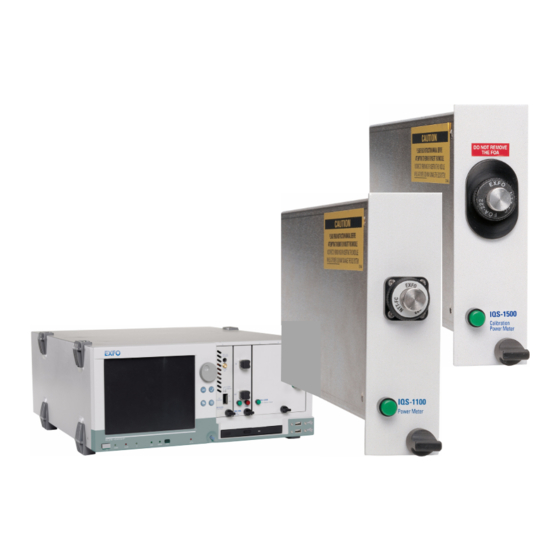
High-power germanium Indium gallium arsenide (InGaAs) Optical detector port LED push IQS-1100 button Power Meter Retaining screw knob The IQS-1100 Power Meter has a high resolution, excellent linearity and provides accurate power measurements over a high dynamic range. Power Meters... - Page 10 Introducing the IQS-1100/IQS-1500 Power Meters Main Features The IQS-1500 Calibration Power Meter is a germanium power meter designed to be used with the IQS platforms. Optical detector port LED push IQS-1500 button Calibration Power Meter Retaining screw knob It is designed to offer you highly precise readings, and is used to check power meter calibration, both in singlemode and multimode.
- Page 11 The graphical display mode shows all channels on a real-time graph, which you can analyze afterwards. The IQS-1100/IQS-1500 Power Meters supports local control (via the IQS Manager software) and remote control (through GPIB, RS-232, or Ethernet TCP/IP using SCPI commands or the provided LabVIEW drivers).
-
Page 12: Typical Applications
Introducing the IQS-1100/IQS-1500 Power Meters Typical Applications Typical Applications Your power meter is suitable for numerous applications, including the following: Insertion loss of passive components in the production environment Component and system monitoring Source stability characterization Absolute power measurements Multicomponent testing... -
Page 13: Conventions
Introducing the IQS-1100/IQS-1500 Power Meters Conventions Conventions Before using the product described in this manual, you should understand the following conventions: ARNING Indicates a potentially hazardous situation which, if not avoided, could result in death or serious injury. Do not proceed unless you understand and meet the required conditions. -
Page 15: Safety Information
Safety Information Your power meter does not contain laser components in itself. However, you will be using it with light sources. ARNING Do not install or terminate fibers while a light source is active. Never look directly into a live fiber and ensure that your eyes are protected at all times. -
Page 17: Getting Started With Your Power Meters
Getting Started with Your Power Meters Inserting and Removing Test Modules AUTION Never insert or remove a module while the controller unit and its expansion units are turned on. This will result in immediate and irreparable damage to both the module and unit. To insert a module into the controller or expansion unit: 1. - Page 18 6. While applying slight pressure to the module, turn the retaining screw knob (located at the bottom of the panel) clockwise until the knob is horizontal. This will secure the module into its “seated” position. IQS-1100/IQS-1500...
- Page 19 Note: You can insert IQ modules into your controller or expansion unit; the IQS Manager software will recognize them. However, the IQS-1100/IQS-1500 locking mechanism (retaining screw) will not work for IQ modules. To remove a module from your controller or expansion unit: 1.
- Page 20 3a. Slide the top of the protective cover into the upper grooves of the unit. 3b. Snap the cover into place by pushing the retaining screw knob. AUTION Failure to reinstall protective covers over empty slots will result in ventilation problems. IQS-1100/IQS-1500...
-
Page 21: Starting The Power Meters Application
Getting Started with Your Power Meters Starting the Power Meters Application Starting the Power Meters Application Your IQS-1100/IQS-1500 Power Meters module can be configured and controlled from its dedicated IQS Manager application. Note: For details about IQS Manager, refer to the IQS platform user guide. - Page 22 Note: To start the corresponding monitor window at the same time, click Start App. & Monitor. The window opens on the Monitors function tab. The main window (shown below) contains all the commands required to control the Power Meters: IQS-1100 Title bar Data display...
- Page 23 (23 C ± 5 You can still perform measurements while the icon is present, but EXFO recommends postponing critical measurements until the warmup period is over, as you might not benefit from the maximum stability and precision your power meter can offer.
- Page 24 Remote: Module controlled remotely, but local commands can also be used. Lockout: Module controlled remotely only. Module/unit status Current date and time For more information about automating or remotely controlling the IQS-1100/IQS-1500 Power Meters, refer to your platform user guide. IQS-1100/IQS-1500...
-
Page 25: Entering Values Using Sliders And Numeric Boxes
Getting Started with Your Power Meters Entering Values Using Sliders and Numeric Boxes Entering Values Using Sliders and Numeric Boxes Many parameters in IQS Manager and module applications can be set using the following tools. Slider Fine-tuning Numeric box button Navigation buttons Slider: Drag it to the desired value on the scale below. -
Page 26: Exiting The Application
To close the application from the main window: Click in the top right corner of the main window. Click the Exit button located at the bottom of the function bar. To close all currently running applications: From IQS Manager, click Close All Applications. IQS-1100/IQS-1500... -
Page 27: Setting Up Your Power Meters
Setting Up Your Power Meters You can set the following parameters on your IQS-1100/IQS-1500: Chanel display Wavelength selection and management Measurement unit selection Display resolution Refresh rate Measurement range Saving and recalling configuration Power Meters... -
Page 28: Naming Channels
The name should be as self-explanatory as possible (for example, Power-Fiber 3). To enter a channel name: 1. Click the Settings function tab. 2. Type in a self-explanatory name in the Name box. 3. Click Apply to confirm your new setting. IQS-1100/IQS-1500... -
Page 29: Selecting The Wavelength
Setting Up Your Power Meters Selecting the Wavelength Selecting the Wavelength When taking accurate measurements, your power meter must be set to the correct wavelength to compensate for the photodetector responsivity at the incident wavelength. Ideally, the power meter’s wavelength should be set as close as possible to that of the optical source being used. -
Page 30: Managing Wavelength Lists
Setting Up Your Power Meters Managing Wavelength Lists Managing Wavelength Lists The wavelengths you want to use with your IQS-1100/IQS-1500 must be entered in the Wavelength list. Please refer to the Certificate of Compliance supplied with your power meter for information on the wavelength range. -
Page 31: Selecting The Measurement Unit
Setting Up Your Power Meters Selecting the Measurement Unit Selecting the Measurement Unit Power measurements can be displayed in dB, dBm, W, or W/W (the latter indicating the ratio between the power received and the reference for the current wavelength and channel). When W or W/W is selected, the software automatically selects W units (pW, nW, μW, mW), depending on the measured power and sensitivity of the detector. -
Page 32: Setting The Display Resolution
3. Click Apply to confirm your new setting. Note: When W or W/W is selected, the display resolution changes to Auto (the appropriate W unit will be used according to the power of the signal detected). It is then impossible to access the display resolution list. IQS-1100/IQS-1500... -
Page 33: Setting The Refresh Rate
Setting Up Your Power Meters Setting the Refresh Rate Setting the Refresh Rate This function allows you to define the refresh rate of the power readings on the display. The refresh rate is the number of times per second that a new power measurement will be displayed on the screen. -
Page 34: Saving And Recalling Configurations
Setting Up Your Power Meters Saving and Recalling Configurations Saving and Recalling Configurations Once you have set the IQS-1100/IQS-1500 Power Meters parameters, you can save your custom configuration and recall it at any time. You can also recall the factory-defined settings. - Page 35 Setting Up Your Power Meters Saving and Recalling Configurations To recall a configuration: 1. Select the Configuration function tab. 2. Click Open. 3. Select the configuration file you wish to recall and confirm your action. You are returned to the application and the new parameters are set. To revert to factory settings: 1.
-
Page 37: Preparing Your Power Meters For A Test
To ensure maximum power and to avoid erroneous readings: Always clean fiber ends as explained below before inserting them into the port. EXFO is not responsible for damage or errors caused by bad fiber cleaning or handling. Ensure that your patchcord has appropriate connectors. Joining mismatched connectors will damage the ferrules. -
Page 38: Nulling Offsets
Your IQS-1100/IQS-1500 Power Meters automatically performs nulling of the offset each time you turn it on. However, you might need to perform a manual nulling of the offset when environmental conditions change significantly or when you are measuring very low power. - Page 39 Preparing Your Power Meters for a Test Nulling Offsets To perform an offset nulling: 1. Install the protective cap over the detector port. 2. Under Channel, click the Nulling button. A message prompts you to ensure that the detector cap is properly installed. 3.
-
Page 41: Measuring Power
Measuring Power Power measurements can be displayed in two ways: absolute relative It is also possible to add an offset value to your power measurement. Displaying Absolute Power When in absolute power, measured values are displayed in either dBm or W units (pW, nW, μW, mW...) and the displayed value represents the absolute optical power reaching the detector within specified uncertainty. - Page 42 5. Return to the Instrument function tab and click Absolute to activate the mode. An absolute power measurement in negative W units indicates that the nulling of the offset was improperly done. If this happens, repeat the offset nulling operation (see Nulling Offsets on page 30). IQS-1100/IQS-1500...
-
Page 43: Measuring Relative Power
Measuring Power Measuring Relative Power Measuring Relative Power Power measurements can be displayed as a deviation from an absolute reference value. The relative power is particularly useful when performing loss measurements. Relative power is displayed in dB when the reference value is measured in dBm. -
Page 44: Using The Offset Function
To enter an offset value: 1. From the Settings function tab, select the Channels tab. 2. From the Offset list, use the arrow buttons to adjust the value. 3. Click Apply to confirm your new setting. IQS-1100/IQS-1500... -
Page 45: Averaging Measurements
AVG marker at the right of the value, indicating that averaging is enabled. In the case of the IQS-1100 Power Meter, you can benefit from an extended absolute power measurement range, up to −100 dBm if the following conditions are met: You must enable the averaging function. -
Page 47: Performing Acquisitions
Performing Acquisitions You can set a location where the acquisitions will be stored when you do your tests. To select a path for storing your acquisitions: 1. From the Settings function tab, select the Data Acquisition tab. 2. Use to select the folder to save your file. Selecting the Sampling Type You can perform different types of samplings with your power meter: Continuous sampling signifies that power measurements are... - Page 48 Remember to click to confirm your settings. Note: Use a lower sampling rate with averaging set to active (see Averaging Measurements on page 37) for greater repeatability when measuring very low power. IQS-1100/IQS-1500...
-
Page 49: Selecting The Acquisition Mode
Performing Acquisitions Selecting the Acquisition Mode Selecting the Acquisition Mode You can use three data acquisition modes, regardless of the type of acquisition you are performing. Timer: the acquisition will last for the length of time you have previously set. Trigger: the power meter will wait for an incoming trigger signal before starting its next acquisition. - Page 50 Click inside the Timer edit box of the Data Acquisition tab and enter the value (or use the arrow buttons next to the list to adjust it). If you are using the numeric box, enter the value in seconds (for example, 120 seconds if you want to enter two minutes). IQS-1100/IQS-1500...
- Page 51 Performing Acquisitions Selecting the Acquisition Mode Setting Up Delayed Acquisition Delay Delayed acquisition starts at a specified time after you start the process, and continues for the time you have previously specified if you have selected a combination of Timed and Delayed acquisition types. To set a delay for your acquisition: 1.
- Page 52 Acquisition will start when measured power of channel A is lower than measured power of channel B. (multichannel power meters only) Note: The trigger defines the condition for starting data acquisition. Once begun, acquisitions will continue for the specified duration, regardless of the measured power. IQS-1100/IQS-1500...
- Page 53 Performing Acquisitions Selecting the Acquisition Mode To set up the power level trigger condition: 1. From Trigger of the Data Acquisition tab, use the arrow buttons next to the Type list to select the desired condition. Note: The X and Y values are displayed in the currently selected unit. 2.
-
Page 54: Starting The Acquisition
Graph function in the same tab (for more information on the graph acquisition and visualization mode, see Performing and Analyzing Graph Acquisitions on page 53). Note: You cannot activate Graph mode after the acquisition has already been started. IQS-1100/IQS-1500... - Page 55 Performing Acquisitions Starting the Acquisition You can also start the acquisition in the Graph tab by clicking the Start button the same way you would in the Control tab. MPORTANT If you change units on the channel using Relative or Absolute mode and that you had enabled Graph mode, the Graph and Start buttons might automatically disable themselves if the resulting changes are not compatible with the base unit used in the graph.
-
Page 56: Consulting Acquired Data
Once you have acquired data, it is possible to view the results in IQS Manager. To view data previously acquired: 1. In IQS Manager, select the Work on Results (Offline) function tab. 2. Click the tab, then click the button corresponding to the application for which you want to see information. IQS-1100/IQS-1500... - Page 57 Performing Acquisitions Consulting Acquired Data 3. In the viewer, retrieve the corresponding file using the button. To view the details pertaining to the channels used for the acquisition, select the General tab. Power Meters...
- Page 58 Performing Acquisitions Consulting Acquired Data To view your acquisition data, select the Data tab. IQS-1100/IQS-1500...
- Page 59 Performing Acquisitions Consulting Acquired Data To view the graph corresponding to your acquisition data, select the Graph tab. To move along the time scale, use the arrow buttons. The single arrow buttons will move by increments or decrements representing 10 % of the current trace scale value. The double arrow buttons will move by increments or decrements of the current screen display (for example, the 10 to 40 seconds display would become 40 to 70 seconds in the figure...
- Page 60 Only the first part of your acquisition file will be displayed in the viewer; to see complete results, you must export the file and view it in a word processing program. To exit the window and return to IQS Manager, click Exit. IQS-1100/IQS-1500...
-
Page 61: Performing And Analyzing Graph Acquisitions
Performing and Analyzing Graph Acquisitions The Graph mode of your power meter allows you to view your acquisition as it is performed, and analyze it once it has been completed. Setting Up Graph Parameters Before acquiring data, you should set the parameters that will help you achieve a better viewing afterwards. - Page 62 If you change the base unit, the channels in the Display tab will automatically change when you switch from a relative unit to an absolute unit or vice versa. To show or hide the grid in the background of the graph display: Click the corresponding button in the Settings tab. IQS-1100/IQS-1500...
-
Page 63: Printing Graph Results
Performing and Analyzing Graph Acquisitions Printing Graph Results Printing Graph Results Once you have acquired data and displayed a graph, it is possible to print out this information. To print your graph results: Click in the Graph Center. Use the arrow buttons to select the printer to use. You can enter a title for your document in the corresponding box. -
Page 64: Using The Zoom Function
Click the area repeatedly until you reach the desired zoom factor. allows you to reduce the trace display at the precise location where you click. Click the area repeatedly until you reach the desired zoom factor. IQS-1100/IQS-1500... - Page 65 Performing and Analyzing Graph Acquisitions Using the Zoom Function allows you to move around the trace to view areas not currently displayed. You can pan upwards and downwards, as well as to the left and right. Note: You can only pan to the right and left if the time scale length is larger than the portion displayed on the screen.
-
Page 66: Displaying And Moving Markers
Zoom tab), the markers will still be visible, but you cannot move them. You must return to the Markers tab to do so. You will notice that the difference between the markers (B − A) is automatically refreshed on the lower part of the tab as you move the markers. IQS-1100/IQS-1500... -
Page 67: Calibrating Other Power Meters With The Iqs-1500
Calibrating Other Power Meters with the IQS-1500 In addition to performing usual power meter functions, your IQS-1500 Calibration Power Meter can be used to calibrate other power meters. This is performed through a step-by-step wizard. As you move along the steps, you will notice that the current step is identified on the left by a circle. -
Page 68: Selecting The Calibration Option
If you selected View report rile, the different reports are now available; click the desired file once to select it. Click Next to proceed to the following step, or to view the report, according to what you have chosen. IQS-1100/IQS-1500... -
Page 69: Entering General Calibration Information
Calibrating Other Power Meters with the IQS-1500 Entering General Calibration Information Entering General Calibration Information The General window allows you to enter information pertaining to the person performing the calibration (the user), the company employing this person, and details pertaining to the Calibration Power Meter used to perform the calibration. -
Page 70: Entering Calibration Conditions
Click it once in the list of available modules. Since you do not need to enter additional information at this point, the lower part of the window is grayed out. Once you have selected the source you want to use, click Next. IQS-1100/IQS-1500... - Page 71 Calibrating Other Power Meters with the IQS-1500 Entering Calibration Conditions To add a source to the list: 1. Click Add. The lower part of the window becomes available. 2. Enter the information pertaining to the new source, including the humidity and temperature values. Note: The humidity and temperature values are the same for all sources in your list.
- Page 72 The lower part of the window is now available. 3. Modify the details about this source. 4. Click Apply to confirm your changes. To remove a source from the list: 1. Select the source from the list by clicking it once. 2. Click Remove. IQS-1100/IQS-1500...
-
Page 73: Entering Dut Information
Calibrating Other Power Meters with the IQS-1500 Entering DUT Information Entering DUT Information The DUT window allows you to enter information about the calibrated DUT (power meter), including details on the DUT (serial number, description, etc.), on the company owning the DUT, plus any useful comment. Note: This information is kept in memory when using the template option as explained in Selecting the Calibration Option on page 60. -
Page 74: Entering Calibration Uncertainties
The Calibration (or Reference) Power Meter uncertainty is provided in the IQS-1500 Power Meter’s calibration report and must be at a 95 % (2σ) confidence level. For example, if the confidence level is specified at 68 % (1σ), you must multiply the uncertainty by a factor of 2. IQS-1100/IQS-1500... - Page 75 Calibrating Other Power Meters with the IQS-1500 Entering Calibration Uncertainties Type A uncertainties are characterized by taking a series of measurements and calculating the standard deviation. The standard deviation of the calibration factor for the DUT is automatically calculated and displayed in the Standard Deviation box of the calibration summary (see Viewing Calibration Summary on page 76).
- Page 76 Previous measurement data Manufacturer’s specifications Data provided in calibration and other reports Type A uncertainties are also assumed to be independent, but normally distributed; therefore, they can be estimated by performing a series of measurements and calculating a standard deviation. IQS-1100/IQS-1500...
- Page 77 Calibrating Other Power Meters with the IQS-1500 Entering Calibration Uncertainties The total uncertainty is calculated by adding (using the root of the sum of the squares) the Type B, Type A and Reference Meter uncertainties and multiplying the results by a factor of two to obtain a confidence level of 95 %, as shown in the following equation: ⎛...
- Page 78 4. Enter the Type B uncertainty values according to the calculations performed earlier. 5. Enter the Reference Meter expanded uncertainty in the corresponding box. Once you are done entering the uncertainty values, click Next to proceed to the next step. IQS-1100/IQS-1500...
-
Page 79: Saving A Template File
Calibrating Other Power Meters with the IQS-1500 Saving a Template File Saving a Template File At this point of the wizard step, you might want to save all the information you have entered in order to reuse it for other calibrations. To save a template for a later use: 1. -
Page 80: Nulling Offsets For Calibration
To perform an offset nulling on your modules: 1. Place a protective cap on the detector ports. 2. Confirm that you have used the protective caps by checking the corresponding box in the window. 3. Click Start NULL Session to start the process. IQS-1100/IQS-1500... -
Page 81: Storing Reference Power Meter Measurements Automatically
Calibrating Other Power Meters with the IQS-1500 Storing Reference Power Meter Measurements Automatically Storing Reference Power Meter Measurements Automatically The Ref. Meter Measurement window allows you to take a series of power measurements automatically on your Calibration Power Meter. You can specify the number of power measurements you want to take, and the time interval between each measurement. - Page 82 5. Click Start to start the calculations. If this result is not satisfactory, you can start over by clicking Erase this result. You must then restart the calculation with Start. Once you are satisfied with your results, proceed to the next step by clicking Next. IQS-1100/IQS-1500...
-
Page 83: Entering Dut Measurements
Calibrating Other Power Meters with the IQS-1500 Entering DUT Measurements Entering DUT Measurements After taking the measurements on your reference power meter, you must take them on the DUT, in the DUT Meter Measurement window. You can enter as many measurements as needed. To add DUT measurements to your calibration procedure: 1. -
Page 84: Viewing Calibration Summary
You can delete erroneous results, or go back to a previous step to obtain more measurements. The calibration factor (CF) is calculated using the following equation: ⎛ ⎞ 1500 ----------------------- - ⎝ ⎠ where = IQS-1500 measured power 1500 = DUT measured power IQS-1100/IQS-1500... - Page 85 Calibrating Other Power Meters with the IQS-1500 Viewing Calibration Summary The standard deviation (all wavelengths) of the mean calibration factor (CF) is calculated using the following equation: ⎛ ⎛ ⎞ ⎞ ⎛ ⎞ ∑ ∑ ⎜ --- - ⎜ ⎟ ⎟...
- Page 86 DUT) Standard deviation of the calibration factor Mean Wavelength calibration of the power factor by meter under which the DUT test (DUT) readings must be multiplied Average Number of power calibration factor measured on measurement IQS-1500 sets IQS-1100/IQS-1500...
-
Page 87: Managing Calibration Reports
Calibrating Other Power Meters with the IQS-1500 Managing Calibration Reports To sort the results according to a precise criterion: Click the corresponding header. A first click will sort the columns alphabetically, while a second click will reverse the order. To add more measurements to your test: In either tab, click Loop for more measurements. - Page 88 1. Type the name of the report in the Report Name box. 2. Click Save Report. You will be prompted to navigate to the desired location for storing the file. 3. Confirm your choice. You will be returned to the Report window. IQS-1100/IQS-1500...
- Page 89 Calibrating Other Power Meters with the IQS-1500 Managing Calibration Reports To print the report: Click Print. A standard Windows print dialog box appears and allows you to select the printing details pertaining to your setup. To change the logo on your report: 1.
-
Page 91: Monitoring Power Meter Modules
10 Monitoring Power Meter Modules When using your IQS-1100/IQS-1500 Power Meters module, either alone or with other modules in a test setup, you can view module data and status using its monitor window in IQS Manager. Using Monitor Windows Monitor windows display basic data about modules. A combination of resizable windows allows you to create an integrated data display (refer to the platform user guide). - Page 92 2. In the Monitor column, select the box next to each module you want to monitor. If you want to monitor all the modules in the current unit, click Select All Monitors. If you want to clear your choices, click Deselect All Monitors. IQS-1100/IQS-1500...
- Page 93 Monitoring Power Meter Modules Using Monitor Windows 3. Click Start Monitor to apply your selection. IQS Manager will display the selected monitor windows on the Monitors function tab. Note: To start the highlighted module’s corresponding application at the same time, click Start App. & Monitor. The application will appear in a different window.
-
Page 94: Using Quicktools
2. Using the arrow button in the upper left corner, select QuickTools. The corresponding monitor window flashes when QuickTools is activated. Note: If you want to open the actual application for your module rather than QuickTools, click Show Controller. IQS-1500 IQS-1100 IQS-1100/IQS-1500... - Page 95 Monitoring Power Meter Modules Using QuickTools To close QuickTools: Click the Close button located at the top of the window. Click outside the QuickTools window. To close a monitor window: Click the button on the upper left of the monitor window and select Remove Monitor.
-
Page 97: 11 Maintenance
11 Maintenance To help ensure long, trouble-free operation: Always clean fiber-optic connectors before using them. Keep the unit free of dust. Clean the unit casing and front panel with a cloth slightly dampened with water. Store unit at room temperature in a clean and dry area. Keep the unit out of direct sunlight. -
Page 98: Cleaning Fixed Connectors
4. With a dry lint-free wiping cloth, gently wipe the same surfaces three times with a rotating movement. 5. Throw out the wiping cloths after one use. 6. Moisten a cleaning tip (2.5 mm tip) with only one drop of isopropyl alcohol. IQS-1100/IQS-1500... - Page 99 9. Continue to turn as you withdraw the cleaning tip. 10. Repeat steps 7 to 9, but this time with a dry cleaning tip (2.5 mm tip provided by EXFO). Note: Make sure you don’t touch the soft end of the cleaning tip and verify the cleanliness of the cotton tip.
-
Page 100: Cleaning Detector Ports
4. While applying light pressure (to avoid breaking the detector window), gently rotate the cleaning tip on the detector window. 5. Repeat step 4 with a dry cleaning tip or blow dry with compressed air. 6. Discard the cleaning tips after one use. IQS-1100/IQS-1500... -
Page 101: Recalibrating The Unit
You should determine the adequate calibration interval for your unit according to your accuracy requirements. Under normal use, EXFO recommends calibrating your unit every year. Power Meters... -
Page 102: Recycling And Disposal (Applies To European Union Only)
This equipment was sold after August 13, 2005 (as identified by the black rectangle). Unless otherwise noted in a separate agreement between EXFO and a customer, distributor or commercial partner, EXFO will cover costs related to the collection, treatment, recovery, and disposal of... -
Page 103: 12 Troubleshooting
System units, then remove and reinsert the module. Unit has locked up. Reboot the Intelligent Test System. LED is burnt out. Call EXFO. Pressing LED push Computer has Reboot the Intelligent Test button does not locked up. System. - Page 104 The offset nulling is Perform an offset nulling with incorrect. protective cap installed. The optical source is Wait for source to stabilize (at unstable. least 60 minutes). The correction factor Reset the correction factor to is incorrect. 0.000 dB or 1.000 W/W. IQS-1100/IQS-1500...
-
Page 105: Viewing Online Documentation
Troubleshooting Viewing Online Documentation Viewing Online Documentation An online version of the IQS-1100/IQS-1500 Power Meters user guide is available at all times from the application. To access the online user guide: Click Help in the function bar. Power Meters... -
Page 106: Contacting The Technical Support Group
Contacting the Technical Support Group To obtain after-sales service or technical support for this product, contact EXFO at one of the following numbers. The Technical Support Group is available to take your calls from Monday to Friday, 8:00 a.m. to 7:00 p.m. - Page 107 Select the Technical Support tab to view phone numbers and active Internet links to EXFO’s Technical Support Group. Use these links to send an information request by email or to access EXFO’s web site. Select the Module Information tab to view the module identification, serial number and firmware version.
-
Page 108: Transportation
Pack the unit in its original packing material when shipping. Avoid high humidity or large temperature fluctuations. Keep the unit out of direct sunlight. Avoid unnecessary shocks and vibrations. IQS-1100/IQS-1500... -
Page 109: 13 Warranty
SPECIAL, INCIDENTAL, OR CONSEQUENTIAL DAMAGES. Liability EXFO shall not be liable for damages resulting from the use of the product, nor shall be responsible for any failure in the performance of other items to which the product is connected or the operation of any system of which the product may be a part. -
Page 110: Exclusions
Warranty Exclusions Exclusions EXFO reserves the right to make changes in the design or construction of any of its products at any time without incurring obligation to make any changes whatsoever on units purchased. Accessories, including but not limited to fuses, pilot lamps, batteries and universal interfaces (EUI) used with EXFO products are not covered by this warranty. -
Page 111: Service And Repairs
5. Return the equipment, prepaid, to the address given to you by support personnel. Be sure to write the RMA number on the shipping slip. EXFO will refuse and return any package that does not bear an RMAnumber. -
Page 112: Exfo Service Centers Worldwide
Warranty EXFO Service Centers Worldwide EXFO Service Centers Worldwide If your product requires servicing, contact your nearest authorized service center. EXFO Headquarters Service Center 400 Godin Avenue 1 866 683-0155 (USA and Canada) Quebec (Quebec) G1M 2K2 Tel.: 1 418 683-5498... -
Page 113: A Technical Specifications
MPORTANT The following technical specifications can change without notice. The information presented in this section is provided as a reference only. To obtain this product’s most recent technical specifications, visit the EXFO Web site at www.exfo.com. General Specifications Model IQS-1102X... - Page 114 2. At a ± 1 °C constant temperature. (at 1310.0 ± 0.1 nm and 1550.0 ± 0.1 nm) (—10 dBm CW) 3. Q0 option, uncertainty at EXFO (0 dBm to —10 dBm CW) reference conditions: • ± 2 % uncertainty at (1310.0 ± 0.1) nm ±...
-
Page 115: Bscpi Command Reference
SCPI Command Reference This appendix presents detailed information on the commands and queries supplied with your IQS-1100/IQS-1500 Power Meters. MPORTANT Since the IQS controllers and expansion units can house many instruments, you must explicitly specify which instrument you want to remotely control. - Page 116 MMEMory[1..n] ACQuisition <StartStop>,CONT ACQuisition? ACQuisition DURation <TimeHour>,<TimeMinute>,<Tim eSecond> DURation? FNAMe <FileName> FNAMe? READ[1..n] [SCALar] POWer SENSe[1..n] AVERage [STATe] <AverageState> [STATe]? CORRection COLLect ZERO ASYNchronous OFFSet [MAGNitude] <CorrectionOffset[<wsp>W/W|DB ]>|MAXimum|MINimum|DEFault [MAGNitude]? [MINimum|MAXimum|DEFault] FREQuency CONTinuous <ContinuousRate[<wsp>HZ]> CONTinuous? CONTinuous CATalog? POWer [DC] REFerence? REFerence IQS-1100/IQS-1500...
- Page 117 SCPI Command Reference Quick Reference Command Tree Command Parameter(s) DISPlay STATe <ReferenceState> STATe? UNIT DBM|W UNIT? WAVelength <Wavelength>|MAXimum|MINimu m|DEFault WAVelength? [MINimum|MAXimum|DEFault] SLINstrument CATalog? CATalog FULL? SNUMber? STATus? STATus OPERation BIT[1..n] CONDition? UNIT[1..n] POWer DB|DBM|W|W/W|WATT|WATT/W POWer? Power Meters...
-
Page 118: Product-Specific Commands-Description
SCPI Command Reference Product-Specific Commands—Description Product-Specific Commands—Description :ABORt[1..n] Description This command is used to stop the acquisition currently in progress. Syntax :ABORt[1..n] Parameter(s) None Example(s) INIT:CONT ON ABOR See Also INITiate:CONTinuous INITiate:CONTinuous? INITiate:IMMediate MMEMory:ACQuisition MMEMory:ACQuisition? IQS-1100/IQS-1500... - Page 119 SCPI Command Reference Product-Specific Commands—Description :FETCh[1..n][:SCALar]:POWer:DC? Description This query returns the stored value on the specified channel. To fetch a specific channel, enter the channel number as a suffix of the FETC keyword. The maximum channel is device-dependent. Channel 1 is always used by default. Syntax :FETCh[1..n][:SCALar]:POWer:DC? Parameter(s)
- Page 120 0 -Zero digit after the decimal point 1 -One digit after the decimal point 2 -Two digit after the decimal point 3 -Three digit after the decimal point 4 -Four digit after the decimal point 5 -Autoresolution Example(s) FORM:DATA 3 See Also FORMat[:DATA]? IQS-1100/IQS-1500...
- Page 121 SCPI Command Reference Product-Specific Commands—Description :FORMat[1..n][:DATA]? Description This query returns the resolution of the power value when dB or dBm is selected for the specified channel. Syntax :FORMat[1..n][:DATA]? Parameter(s) None Response Syntax <FormatData> Response(s) FormatData: The response data syntax for <FormatData> is defined as a <NR3 NUMERIC RESPONSE DATA>...
- Page 122 SCPI Command Reference Product-Specific Commands—Description :INITiate[1..n][:IMMediate] Description This command stores one value in the buffer for all channels. Syntax :INITiate[1..n][:IMMediate] Parameter(s) None Example(s) INIT:IMM FETC1:POW:DC? INIT FETC1:POW:DC? See Also FETCh[:SCAL]:POWer:DC? READ[:SCAL]:POWer:DC? ABORt INITiate:CONTinuous MMEMory:ACQuisition IQS-1100/IQS-1500...
- Page 123 SCPI Command Reference Product-Specific Commands—Description :INITiate[1..n]:CONTinuous Description Sets continuous acquisition mode and starts or stops the acquisition. Syntax :INITiate[1..n]:CONTinuous<wsp><Continuous Acquisition> Parameter(s) ContinuousAcquisition: The program data syntax for <ContinuousAcquisition> is defined as a <Boolean Program Data> element. The <ContinuousAcquisition> special forms ON and OFF are accepted on input for increased readability.
- Page 124 <ContinuousAcqState> is defined as a <NR1 NUMERIC RESPONSE DATA> element. This parameter allows to set the state of continuous acquisition. 0 - Continuous acquisition is stopped. 1 - Continuous acquisition is running. Example(s) INIT:CONT? See Also ABORt INITiate:CONTinuous MMEMory:ACQuisition MMEMory:ACQuisition? IQS-1100/IQS-1500...
- Page 125 SCPI Command Reference Product-Specific Commands—Description :MMEMory[1..n]:ACQuisition Description This command initiates a data acquisition. Acquires data at the selected sampling rate. The acquisition will be saved to the system hard disk in the file : <filename to specified> The acquisition will continue for the duration specified in the MMEM:ACQ:DUR command.
- Page 126 SCPI Command Reference Product-Specific Commands—Description :MMEMory[1..n]:ACQuisition The acquisition state can be modified with: CONT -sets the Continuous acquisition rate. Example(s) MMEM:ACQ 1, CONT MMEM:ACQ? MMEM:ACQ 0, CONT See Also MMEMory:ACQuisition? MMEMory:ACQuisition:DURation MMEMory:ACQuisition:DURation? ABORt INITiate:CONTinuous INITiate:IMMediate IQS-1100/IQS-1500...
- Page 127 SCPI Command Reference Product-Specific Commands—Description :MMEMory[1..n]:ACQuisition? Description This query returns the acquisition flag. 0 - No memory acquisition running. 1 - Memory acquisition running. Syntax :MMEMory[1..n]:ACQuisition? Parameter(s) None Response Syntax <AcqOnOff> Response(s) AcqOnOff: The response data syntax for <AcqOnOff> is defined as a <NR1 NUMERIC RESPONSE DATA>...
- Page 128 Used to set the duration of acquisition in minutes. TimeSecond: The program data syntax for <TimeSecond> is defined as a <DECIMAL NUMERIC PROGRAM DATA> element. Used to set the duration of acquisition in seconds. Example(s) MMEM:ACQ:DUR 1,1,1 See Also MMEMory:ACQuisition:DURation? MMEMory:ACQuisition INITiate:CONTinuous IQS-1100/IQS-1500...
- Page 129 SCPI Command Reference Product-Specific Commands—Description :MMEMory[1..n]:ACQuisition: DURation? Description This query returns the duration of the acquisition. Syntax :MMEMory[1..n]:ACQuisition:DURation? Parameter(s) None Response Syntax <AcqTime> Response(s) AcqTime: The response data syntax for <AcqTime> is defined as a <DEFINITE LENGTH ARBITRARY BLOCK RESPONSE DATA> element. This query returns the duration for the acquisition in hour, minute, second format.
- Page 130 Syntax :MMEMory[1..n]:FNAMe<wsp><FileName> Parameter(s) FileName: The program data syntax for <FileName> is defined as a <STRING PROGRAM DATA> element. Changes the file name and storage location. Example: PmACQ.tra or D:IQS ManagerUser FilesIqs1x00PmACQ.tra Example(s) MMEM:FNAM PmACQ.tra See Also MMEMory:FNAMe? IQS-1100/IQS-1500...
- Page 131 SCPI Command Reference Product-Specific Commands—Description :MMEMory[1..n]:FNAMe? Description This query returns the acquisition file's name and storage location. Syntax :MMEMory[1..n]:FNAMe? Parameter(s) None Response Syntax <FileName> Response(s) FileName: The response data syntax for <FileName> is defined as a <STRING RESPONSE DATA> element. This query returns the files name and storage location.
- Page 132 <PowerMeasurement> is defined as a <NR3 NUMERIC RESPONSE DATA> element. This query returns the current power. If the returned value is: 9221120237577961472, power is under range 9221120238114832384, power is over range 9221120238651703296, power is invalid 9221120239188574208, channel is inactive IQS-1100/IQS-1500...
- Page 133 SCPI Command Reference Product-Specific Commands—Description :READ[1..n][:SCALar]:POWer:DC? Example(s) READ:SCAL:POW:DC? Returns -1.254000E+001 READ:SCAL:POW:DC? Returns 9221120237577961472 (UNDERRANGE) READ:SCAL:POW:DC? Returns 9221120238114832384 (OVERRANGE) READ:SCAL:POW:DC? Returns 9221120238651703296 (INVALID) READ:SCAL:POW:DC? Returns 9221120239188574208 (INACTIVE) See Also INITiate:IMMediate FETCh:SCALar:POWer:DC? Power Meters...
- Page 134 The <AverageState> special forms ON and OFF are accepted on input for increased readability. ON corresponds to 1 and OFF corresponds to 0. State of averaging: 0 or OFF -Disables Averaging 1 or ON -Enables Averaging Example(s) SENS:AVER:STAT ON See Also SENSe:AVERage:STATe? IQS-1100/IQS-1500...
- Page 135 SCPI Command Reference Product-Specific Commands—Description :SENSe[1..n]:AVERage[:STATe]? Description This query returns the current averaging state. Syntax :SENSe[1..n]:AVERage[:STATe]? Parameter(s) None Response Syntax <AverageState> Response(s) AverageState: The response data syntax for <AverageState> is defined as a <NR1 NUMERIC RESPONSE DATA> element. State of averaging. 0 -Averaging is disabled 1 -Averaging is enabled Example(s)
- Page 136 This command is not executed if a data acquisition is in progress. In that case, the "acquisition in progress" message will be returned. This command will take at least 30 seconds to complete. See Also SENSe:CORRection:COLLect:ZERO:ALL SENSe:CORRection:COLLect:ZERO:ASYNchrono SENSe:CORRection:COLLect:ZERO:ASYNchrono us:ALL IQS-1100/IQS-1500...
- Page 137 SCPI Command Reference Product-Specific Commands—Description :SENSe[1..n]:CORRection:COLLect: ZERO:ALL Description This command performs an synchronous offset nulling measurement on all channels. Syntax :SENSe[1..n]:CORRection:COLLect:ZERO:ALL Parameter(s) None Example(s) SENS:CORR:COLL:ZERO:ALL Notes This command is not executed if a data acquisition is in progress. In that case, the "acquisition in progress"...
- Page 138 This command is not executed if a data acquisition is in progress. In that case, the "acquisition in progress" message will be returned. This command will take at least 30 seconds to complete. See Also SENSe:CORRection:COLLect:ZERO SENSe:CORRection:COLLect:ZERO:ALL SENSe:CORRection:COLLect:ZERO:ASYNchrono us:ALL IQS-1100/IQS-1500...
- Page 139 SCPI Command Reference Product-Specific Commands—Description :SENSe[1..n]:CORRection:COLLect: ZERO:ASYNchronous:ALL Description This command performs an asynchronous offset nulling measurement on all channels. Syntax :SENSe[1..n]:CORRection:COLLect:ZERO:ASYNc hronous:ALL Parameter(s) None Example(s) SENS:CORR:COLL:ZERO:ASYN:ALL Notes This command is not executed if a data acquisition is in progress. In that case, the "acquisition in progress"...
- Page 140 MAXimum allows to set the instrument to the greatest supported value. DEFault allows the instrument to select a value for the <CorrectionOffset> parameter. Sets the offset for the specified channel. Example(s) SENS:CORR:OFFS:MAGN 2.0 See Also SENSe:CORRection:OFFSet:[MAGNitude]? IQS-1100/IQS-1500...
- Page 141 SCPI Command Reference Product-Specific Commands—Description :SENSe[1..n]:CORRection:OFFSet [:MAGNitude]? Description This query returns the offset value in W/W. If no channel was specified, the default channel used is 1. Syntax :SENSe[1..n]:CORRection:OFFSet[:MAGNitude]?[ <wsp>MINimum|MAXimum|DEFault] Parameter(s) Parameter 1: The program data syntax for the first parameter is defined as a <CHARACTER PROGRAM DATA>...
- Page 142 SCPI Command Reference Product-Specific Commands—Description :SENSe[1..n]:CORRection:OFFSet [:MAGNitude]? Response(s) CorrectionOffset: The response data syntax for <CorrectionOffset> is defined as a <NR3 NUMERIC RESPONSE DATA> element. This query returns the offset for the specified channel Example(s) SENS:CORR:OFFS:MAGN? See Also SENSe:CORRection:OFFSet:[MAGNitude] IQS-1100/IQS-1500...
- Page 143 SCPI Command Reference Product-Specific Commands—Description :SENSe[1..n]:FREQuency:CONTinuous Description This command sets the continuous acquisition rate in Hz. Syntax :SENSe[1..n]:FREQuency:CONTinuous<wsp>< ContinuousRate[<wsp>HZ]> Parameter(s) ContinuousRate: The program data syntax for <ContinuousRate> is defined as a <DECIMAL NUMERIC PROGRAM DATA> element followed by an optional <SUFFIX PROGRAM DATA>...
- Page 144 Hz. Syntax :SENSe[1..n]:FREQuency:CONTinuous? Parameter(s) None Response Syntax <ContinuousRate> Response(s) ContinuousRate: The response data syntax for <ContinuousRate> is defined as a <NR2 NUMERIC RESPONSE DATA> element. This query returns the current continuous acquisition rate. Example(s) SENS:FREQ:CONT? See Also SENSe:FREQuency:CONTinuous SENSe:FREQuency:CONTinuous:CATalog? IQS-1100/IQS-1500...
- Page 145 SCPI Command Reference Product-Specific Commands—Description :SENSe[1..n]:FREQuency:CONTinuous: CATalog? Description This query returns the list of available continuous acquisition rates in Hz. Syntax :SENSe[1..n]:FREQuency:CONTinuous:CATalog? Parameter(s) None Response Syntax <ContinuousList> Response(s) ContinuousList: The response data syntax for <ContinuousList> is defined as a <DEFINITE LENGTH ARBITRARY BLOCK RESPONSE DATA>...
- Page 146 None Response Syntax <Reference> Response(s) Reference: The response data syntax for <Reference> is defined as a <NR3 NUMERIC RESPONSE DATA> element. This query returns the reference value for the specified channel. Example(s) SENS:POW:REF? See Also SENSe:POWer:[DC]:REFerence:ALL SENSe:POWer:[DC]:REFerence:DISPlay SENSe:POWer:[DC]:REFerence:STATe SENSe:POWer:[DC]:REFerence:STATe? IQS-1100/IQS-1500...
- Page 147 SCPI Command Reference Product-Specific Commands—Description :SENSe[1..n]:POWer[:DC]:REFerence: Description This command performs a new reference measurement and changes the display to show relative power (dB or W/W) for all channels. Syntax :SENSe[1..n]:POWer[:DC]:REFerence:ALL Parameter(s) None Example(s) SENS:POW:REF:ALL SENS:POW:REF? SENS2:POW:REF? Notes This command is not executed if a data acquisition is in progress.
- Page 148 (dB or W/W) for the specified channel. Syntax :SENSe[1..n]:POWer[:DC]:REFerence:DISPlay Parameter(s) None Example(s) SENS:POW:REF:DISP SENS:POW:REF? Notes This command is not executed if a data acquisition is in progress. In that case, the "Acquisition in progress" message will be returned. See Also SENSe:POWer:[DC]:REFerence? SENSe:POWer:[DC]:REFerence:ALL SENSe:POWer:[DC]:REFerence:STATe SENSe:POWer:[DC]:REFerence:STATe? IQS-1100/IQS-1500...
- Page 149 SCPI Command Reference Product-Specific Commands—Description :SENSe[1..n]:POWer[:DC]:REFerence: STATe Description This command selects whether absolute (dBm or W) or relative (dB or W/W) power measurements are performed. Syntax :SENSe[1..n]:POWer[:DC]:REFerence:STATe<ws p><ReferenceState> Parameter(s) ReferenceState: The program data syntax for <ReferenceState> is defined as a <Boolean Program Data> element.
- Page 150 The response data syntax for <ReferenceState> is defined as a <CHARACTER RESPONSE DATA> element. Current reference mode, where: 0 - is the absolute mode(dBm or W). 1 - is the relative mode (dB or W/W). Example(s) SENS:POW:REF:STAT? See Also SENSe:POWer:[DC]:REFerence? SENSe:POWer:[DC]:REFerence:ALL SENSe:POWer:[DC]:REFerence:DISPlay SENSe:POWer:[DC]:REFerence:STATe IQS-1100/IQS-1500...
- Page 151 SCPI Command Reference Product-Specific Commands—Description :SENSe[1..n]:POWer[:DC]:UNIT Description This command changes the absolute measurement display unit: dBm or W for the specified channel. Syntax :SENSe[1..n]:POWer[:DC]:UNIT<wsp>DBM|W Parameter(s) Unit: The program data syntax for the first parameter is defined as a <CHARACTER PROGRAM DATA> element.
- Page 152 Syntax :SENSe[1..n]:POWer[:DC]:UNIT? Parameter(s) None Response Syntax <Unit> Response(s) Unit: The response data syntax for <Unit> is defined as a <CHARACTER RESPONSE DATA> element. Current power unit, either DBM or WATT. Example(s) SENS:POW:UNIT? See Also SENSe:POWer[:DC]:UNIT UNIT:POWer UNIT:POWer? IQS-1100/IQS-1500...
- Page 153 SCPI Command Reference Product-Specific Commands—Description :SENSe[1..n]:POWer:WAVelength Description This command selects a new operating wavelength on the specified channel. If no channel was specified, the default value used is Syntax :SENSe[1..n]:POWer:WAVelength<wsp><Wave length>|MAXimum|MINimum|DEFault Parameter(s) Wavelength: The program data syntax for <Wavelength> is defined as a <numeric_value>...
- Page 154 SCPI Command Reference Product-Specific Commands—Description :SENSe[1..n]:POWer:WAVelength Example(s) SENS:POW:WAV 0.000001310 SENS:POW:WAV 1310 nm Notes See the instrument's user guide for the exact spectral range for each detector type. See Also SENSe:POWer:WAVelength? IQS-1100/IQS-1500...
- Page 155 SCPI Command Reference Product-Specific Commands—Description :SENSe[1..n]:POWer:WAVelength? Description This query returns the currently selected wavelength on the specified channel. If no channel was specified, the default value used is Syntax :SENSe[1..n]:POWer:WAVelength?[<wsp>MINi mum|MAXimum|DEFault] Parameter(s) Parameter 1: The program data syntax for the first parameter is defined as a <CHARACTER PROGRAM DATA>...
- Page 156 <NR3 NUMERIC RESPONSE DATA> element. This query returns the current wavelength in meters for the specified channel. Any wavelength within spectral range of the power meter optical detector at 1 nm resolution (0.1 nm for the IQS-1500) Example(s) SENS:POW:WAV? See Also SENSe:POWer:WAVelength IQS-1100/IQS-1500...
- Page 157 SCPI Command Reference Product-Specific Commands—Description :SLINstrument:CATalog? Description This query returns a comma-separated list of <STRING RESPONSE DATA>, which contains the names of all channels of the module. If no channels are defined, a single null <STRING RESPONSE DATA> is returned. This is not affected by a *RST command.
- Page 158 <STRING RESPONSE DATA> element. The list of <STRING RESPONSE DATA> contains the names of all channels in the module. The immediately following <NR1 NUMERIC RESPONSE DATA> formatted number is the associated channel number. Example(s) SLIN:CAT:FULL? See Also SLINstrument:CATalog? IQS-1100/IQS-1500...
- Page 159 SCPI Command Reference Product-Specific Commands—Description :SNUMber? Description This query returns a value indicating the module's serial number. Syntax :SNUMber? Parameter(s) None Response Syntax <SerialNumber> Response(s) SerialNumber: The response data syntax for <SerialNumber> is defined as a <STRING RESPONSE DATA> element. The <SerialNumber>...
- Page 160 READY, means the module is ready, BUSY, means the module is busy, DISCONNECTED, means the module is disconnected, DEFECTIVE, means the module is defective and UNCONFIGURED, means the module is not configured. Example(s) STAT? Returns READY (Module is ready.) IQS-1100/IQS-1500...
- Page 161 SCPI Command Reference Product-Specific Commands—Description :STATus:OPERation:BIT[1..n]: CONDition? Description This query returns the state of a specific bit. For the moment, only bit <8> was developed. This bit is used to return the state of the module. If the bit = 0, the module is ready. If the bit = 1, the module is busy.
- Page 162 Set the power unit for the specified channel. Example(s) UNIT:POW DBM Notes This command is not executed if a data acquisition is in progress. In that case, the "Acquisition in progress" message will be returned. See Also UNIT:POWer? SENSe:POWer[:DC]:UNIT SENSe:POWer[:DC]:UNIT? IQS-1100/IQS-1500...
- Page 163 SCPI Command Reference Product-Specific Commands—Description :UNIT[1..n]:POWer? Description This query returns the current power unit for the specified channel. Syntax :UNIT[1..n]:POWer? Parameter(s) None Response Syntax <PowerUnit> Response(s) PowerUnit: The response data syntax for <PowerUnit> is defined as a <CHARACTER RESPONSE DATA> element.
-
Page 165: C Calibration Report Sample
Calibration Report Sample Here is an example of long-form report. The short-form report will be similar, but contains less uncertainty-related information. 1 of 2 EXFO Inc. 465 Godin Ave Vanier (QC) Canada G1M 3G7 CALIBRATION REPORT Customer: EXFO Address: Service center, EXFO3, Description: 4-Ch power meter Serial no.: EME 0103 2641... - Page 166 Source power stability Standard deviation 2.07 Reference meter spectral sensitivity 1.00 Reference meter calibration uncertainty (%) DUT spectral sensitivity 1.00 Setup reproducibility 1.00 Reference meter 2.00 Comments: Prepared by: 11/27/2002 Date Metrologist name Metrologist Metrology Office Approved by: Date IQS-1100/IQS-1500...
-
Page 167: Index
........98 template ..........60 all wavelengths tab ........78 template file........... 71 application uncertainties .......... 66 contacting EXFO support from ....99 viewing reports ........79 exiting ........... 18 viewing summary........76 starting, single-module......13 calibration mode auto. - Page 168 103 save ............26 erasing graph display ........55 connector errors in uncertainty calculation . 68 EXFO service centers ........104 connectors, cleaning ........90 EXFO support e-mail........99 consulting data ........... 48 EXFO Web site ..........99 contact information, EXFO ......
- Page 169 Index module insertion........... 9 identification label ........98 monitoring..........83 identification, slot ........16 removal............ 9 information status ............. 16 for calibration........61 module information on DUT for calibration ......65 firmware version number....... 99 inserting a module ........9 module identification number ....
- Page 170 ....70 reference power meter wavelength ..........21 spectral response........66 setup reproducibility........67 storing measurements ......73 shipping to EXFO........103 uncertainties........66, 70 short report ..........79 refresh rate..........25 showing relative power ..........35 grid ............
- Page 171 Index specifications, product ......105 user-defined spectral response of the DUT....... 67 channel name ........20 stabilization time for power meter ....15 data file ..........41 standard deviation sampling .......... 39, 40 of the calibration factor......76 of the power measurements....73 starting acquisition ........
- Page 172 EXFO ASIA-PACIFIC 151 Chin Swee Road SINGAPORE 169876 #03-29, Manhattan House Tel.: +65 6333 8241 · Fax: +65 6333 8242 TOLL-FREE (USA and Canada) 1 800 663-3936 © 2008 EXFO Electro-Optical Engineering Inc. All rights reserved. Printed in Canada (2008-08)
Need help?
Do you have a question about the IQS-1100 and is the answer not in the manual?
Questions and answers