Table of Contents
Advertisement
Quick Links
Advertisement
Table of Contents

Related Manuals for Ecoflam BLU 3000.1 PRE TC


Summary of Contents for Ecoflam BLU 3000.1 PRE TC
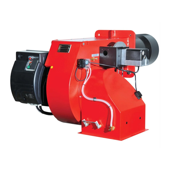
- Page 1 BLU 3000.1 PRE BLU 4000.1 PRE Technical data Operating instructions Electric diagrams Spare parts list Gas train manual is separate BLU 3000.1 PRE TC 3145124 BLU 3000.1 PRE TL 3145125 BLU 4000.1 PRE TC 3145126 BLU 4000.1 PRE TL 3145127...
- Page 2 Exhaust gas test Start-up Adjusting the max air flow rate Firing head setting Servomotor pre-setting Adjusting the intermediate burner capacity Pressure switch adjustment Maintenance program Troubleshooting instructions Operating troubles Appendix Control box - Damper actuators Electrical diagrams Spare parts list 420010829401 www.ecoflam-burners.com...
-
Page 3: General Warnings - Conformity Declaration
Ecoflam burners have been designed and built in compliance with all current regulations and directives. All burners comply to the safety and energy saving operation regulations within the standard of their respective performance range. -
Page 4: Burner Designation
BURNER DESIGNATION BLU 3000.1 PRE TC RANGE NAME BY FUEL TYPE MODEL SIZE BLU 3000.1 3000 kW EMISSIONS Standard Class 2 - GAS EN676 (<120 mg/kWh) Low NOx Class 3 - GAS EN676 (<80 mg/kWh) OPERATION TYPE 2 stages soft start 2 stages progressive mechanical... -
Page 5: Burner Description
8. Burner fixing flange 9. Air flap regulation 12. Lifting eyebolts 14. Gas servomotor Control panel 1 - Fuse 2 - Termal lock-out lamp 3 - Working lamp 4 - Main switch I / O 5 - Display 420010829401 www.ecoflam-burners.com... - Page 6 WARNING: EN676 compulsory kit and accessories in order to comply to the safety regulations. Additional accessories and kits shall be installed by the installer in accordance to the local safety regulations and codes of practise. Gas governor / Filter Modulation Kit Max Pressure switch Other accessories FGDR - FILTER KITMD-RWF50 KITPRES50 Compulsory EN676 Probe-... KITPRES150 420010829401 www.ecoflam-burners.com...
-
Page 7: Technical Data
Lab tests Sound pressure level with silencer 81,8 Ambient temperature storage -20°…+70° C Min/Max Ambient temperature use -10°…+60° C GAS CATEGORY BY COUNTRY Gas category Country BE CH CZ DE DK ES FR GB GR HU NO PL 420010829401 www.ecoflam-burners.com... - Page 8 1000 2000 3000 4000 5000 6000 7000 8000 9000 10000 11000 12000 13000 14000 15000 16000 17000 adapt it to some special boiler Nm 3 /h 1000 1100 1200 1300 1400 1500 1600 1700 or application. 420010829401 www.ecoflam-burners.com...
-
Page 9: Overall Dimensions
Make sure that between the boiler and the blast tube proper insulation is fitted. Packaging (only burner) Model BLU 3000.1 1580 1630 1090 230(241,2) BLU 4000.1 1580 1630 1090 249,5 420010829401 www.ecoflam-burners.com... - Page 10 Any failure of the flame signal at the end of position and proceed with the restart of the the safety period and a flame signal during burner. 420010829401 www.ecoflam-burners.com...
-
Page 11: Installation
20 mm The setting of the mixing and ignition unit according to the boiler output will be performed during commissioning procedure. Ignition Electrode Elettrodo di accensione SECTION B-B 3. Check that the head is preset at 50%. 420010829401 www.ecoflam-burners.com... - Page 12 (furnace) and allow the boiler door to be GAS VALVES AND INSTRUMENTS GROUP must be duly certified. swivelled out if required. The gas valves and instruments group can be connected directly to the gas feed line. 420010829401 www.ecoflam-burners.com...
- Page 13 BLU 3000.1 WARNING: Note that the head loss diagram is only indicative and does vary depending on the setting of the head. OUTPUT - Stm3/h 420010829401 www.ecoflam-burners.com...
- Page 14 VGD 40.080 + F- DN80 VGD 20.503 VGD 40.080 VGD 40.100 + F- DN100 VGD 40.100 1C.2 flow m flow m LEGENDA Pf: Back pressure of furnace Pb: Pressure of burner (combustion head + complete gas train) Pin: Minimum inlet pressure 420010829401 www.ecoflam-burners.com...
- Page 15 VGD 40.065 VGD 40.080 + F- DN 80 VGD 40.080 VGD 40.100 + F- DN100 VGD 40.100 flow m LEGENDA Pf: Back pressure of furnace Pb: Pressure of burner (combustion head + complete gas train) Pin: Minimum inlet pressure 420010829401 www.ecoflam-burners.com...
- Page 16 3 kW. 230V the electrical scheme. For more information, please contact the Adapters, multiple plugs and extension Ecoflam staff. cables may not be used for the equipment’s power supply. LEGENDA An omnipolar switch in accordance with HLB: lock-out lamp...
- Page 17 • Check that control box is unlocked and in its original position. • A standard-compliant measuring point must be available, the exhaust gas duct up to the measuring point must be free of leaks to prevent anomalies in the measurement results. 420010829401 www.ecoflam-burners.com...
-
Page 18: Exhaust Gas Test
- and CO 2500 for heavy oil S (CO max = 15,60%) 2000 1500 = 21 CO max - CO gem = % 1000 gem = % CO measured on dry flue gases Fan capacity reduced by [%] 420010829401 www.ecoflam-burners.com... - Page 19 – Servomotor STE... - Air damper motor pre-setting Air adjustment is accomplished through LAMTEC parameters setting. Refer to LAMTEC manual attacched. 420010829401 www.ecoflam-burners.com...
- Page 20 The maximum gas pressure switch has the function to check that the gas pressure after the gas train and before the head does not exceed the pre-set limits. Max gas pressure switch: it is available as a kit for different pressure. 420010829401 www.ecoflam-burners.com...
-
Page 21: Maintenance Program
The exhaust gas loss can be calculated as follows: as follows: = exhaust gas temperature [°C] = combustion air temperature [°C] 0,37 0,49 = volumetric content of carbon = (195-22)( + 0,009) = 7,48% = (195-22)( + 0,007) = 7,83% dioxide [%] 10,8 12,8 420010829401 www.ecoflam-burners.com... - Page 22 ATTENTION: Check the position of the electrodes after any intervention as wrong position could cause ignition troubles. 59 mm SECTION A-A Elettrodo di rivelazione Ionization Probe 20 mm Ignition Electrode Elettrodo di accensione SECTION B-B GAS FILTER CLEANING 420010829401 www.ecoflam-burners.com...
-
Page 23: Troubleshooting Instructions
Do not attempt to open or carry out repairs on the control unit. key in a parameter window.Use a flushing, red ENTER key to release Refer to LAMTEC manual attacched. a fault interlocker.If the ENTER key is permanently lit red, a fault with an automatic restart is displayed. 420010829401 www.ecoflam-burners.com... - Page 24 APPENDIX Electrical diagrams 420010829401 www.ecoflam-burners.com...
- Page 25 APPENDIX Electrical diagrams 420010829401 www.ecoflam-burners.com...
- Page 26 APPENDIX Spare parts list 420010829401 www.ecoflam-burners.com...
- Page 27 STE 4,5 Q3.51/6 3NM R 65301001 65301001 STE 4,5 B0.37/6-R 0.8NM 65300527 65300527 38 SUPPORT 65320476 65320476 39 COVER 65326894 65326894 40 THROTTLE GROUP 3" STE 4,5 0.8N 65326913 65326913 TC = SHORT HEAD TL = LONG HEAD 420010829401 www.ecoflam-burners.com...
- Page 28 Ecoflam Bruciatori S.p.A. reserves the right to make any adjustments, without prior notice, which is considered necessary or useful to its products, without affecting their main features Ecoflam Bruciatori S.p.A. si riserva il diritto di apportare ai prodotti le modifiche che riterrà necessarie o utili, senza pregiudicarne le caratteristiche principali.
Need help?
Do you have a question about the BLU 3000.1 PRE TC and is the answer not in the manual?
Questions and answers