
Related Manuals for Ecoflam BLU 8000.1 PR


Summary of Contents for Ecoflam BLU 8000.1 PR
- Page 1 GAS BURNERS www.eacoon.com BLU 7000.1 PR BLU 8000.1 PR BLU 10000.1 PR BLU 12000.1 PR Technical data Operating instructions Electric diagrams Spare parts list Gas train manual is separate KIT PER 3142589 3143029...
- Page 2 INDEX BLU 7000.1 PR BLU 8000.1 PR BLU 10000.1 PR BLU 12000.1 PR 1000 2000 3000 4000 5000 6000 7000 8000 9000 10000 11000 12000 13000 14000 General warnings - Conformity declaration Burner designation - Modular delivery system Burner description...
-
Page 3: General Warnings - Conformity Declaration
Ecoflam burners have been designed and built in compliance with all current regulations and directives. All burners comply to the safety and energy saving operation regulations within the standard of their respective performance range. -
Page 4: Burner Designation
BURNER DESIGNATION BLU 8000.1 PR TC SGT 230-400-50 RANGE NAME BY FUEL TYPE MODEL SIZE (Gas: kW; Oil: kg/h) BLU 8000.1 8000 kW EMISSIONS Standard Class 2 - GAS EN676 (<120 mg/kWh) Low NOx Class 3 - GAS EN676 (<80 mg/kWh) OPERATION TYPE... -
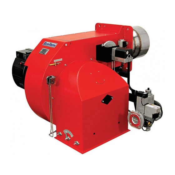
Page 5: Burner Description
BURNER DESCRIPTION LEGENDA 12. Lifting eyebolts GTCP 1. Housing 13. Mechanical cam gas 2. Electrical control panel 15. Servomotor for gas and air 3. Blower motor 16. Gas train 5. Hinge flange 19. Gas filter 6. Blast tube 20. Ball valve EXIT 7. - Page 6 BURNER DESCRIPTION Gas train - Kit - Accessories: assembly to the burner 143 Antivibration coupling To be supplied by the installer 144 Gas governor 150 Batterfly valve 151 Gas train Landis VGD..155 Pilot gas train 160 Kit tightness control (optional) 170 Kit tightness control for pilot gas valve (optional) 313 Min.gas pressure switch 314 Max.gas pressure switch (optional)
-
Page 7: Technical Data
TECHNICAL DATA MODEL BLU 7000.1 BLU 8000.1 BLU 10000.1 BLU 12000.1 7.500 8.500 10.500 13.000 Thermal power max. 6.450.000 7.310.000 9.030.000 11.180.000 kcal/h 1.500 2.000 2.500 2.700 Thermal power min. 1.290.000 1.720.000 2.150.000 2.322.000 kcal/h Operation mode Progressive mechanical gas - Modulating with PID Type Regulation ratio nominal 1÷4 GAS... -
Page 8: Working Fields
WORKING FIELDS Calculation of mbar burner output Q F = Burner output (kW) Q N = Rated boiler output(kW) BLU 12000.1 = Boiler efficiency (%) Q F = Q N x 100 BLU 10000.1 BLU 8000.1 BLU 7000.1 Working fields The working field shows burner output as a function of combustion chamber pressure. -
Page 9: Overall Dimensions
OVERALL DIMENSIONS D - D1 D = Short head D1= Long head Dimensions (mm) BLU 7000.1 1210 1212 1270 BLU 8000.1 1280 1212 1270 BLU 10000.1 1310 1212 1270 BLU 12000.1 1420 1212 1270 HOW TO INSTALL THE GAS TRAIN Burner-boiler mounting flange INTO THE BURNER AND CALCULATE THE OVERALL DIMENSIONS:... -
Page 10: Startup Mode
GAS OPERATING MODE - GENERAL SAFETY FUNCTIONS START-UP MODE GAS OPERATING MODE As soon as the furnace system is required control box so that the safety shut-off After the flame has developed the load to supply heat, the burner control circuit valves will be opened. -
Page 11: Installation
INSTALLATION Fitting the burner to the boiler WARNING: handling and moving operations must be carried out by specialised personnel. Use the eyebolts to lift the burner in order that it will not overturn and fall down. To perform the installation of the burner into the boiler drill the boiler plate according to the dimension given on this manual and place the burner towards it by... - Page 12 INSTALLATION Gas line CONNECTION DIAGRAM FOR BURNERS WITH 100 Burner 107 Pilot gas filter/governor SEPARATE PILOT (GAS TRAIN LANDIS VGD...) 120 Air damper 141 Ball valve 142 Gas filter 143 Antivibration coupling To be supplied by the installer 144 Gas governor 150 Batterfly valve 151 Gas train Landis VGD..
- Page 13 INSTALLATION Pilot gas train, kit and accessories connection - head loss diagram PILOT GAS TRAIN CONNECTION The pilot gas train is already installed to the burner and shall be connected to the main gas supply line preferebly with flexible pipe. The pilot gas train is composed of n°...
- Page 14 INSTALLATION Gas pressure loss diagrams PRESSURE DROP includes: “COMBUSTION HEAD + GAS TRAIN + GAS GOVERNOR & FILTER” as per EN676 Standard. Back pressure of boiler (or other applications) must be added/included in order to have the total min pressure drop. Advisable gas Inlet gas pressure Inlet gas pressure...
- Page 15 Spring color Diagram governor & filter MIN [mbar] MAX [mbar] VGD 40.125 yellow FILTER DN 125 VGD 40.100 yellow BLU 8000.1 PR FILTER DN 100 MULTICALOR 800.1 MULTIFLAM 800.1 VGD 40.080 yellow FILTER DN 80 6C.2 VGD 40.065 yellow FILTER DN 65 VGD 40.065 + F- DN 65...
- Page 16 INSTALLATION Gas pressure loss diagrams PRESSURE DROP includes: “COMBUSTION HEAD + GAS TRAIN + GAS GOVERNOR & FILTER” as per EN676 Standard. Back pressure of boiler (or other applications) must be added/included in order to have the total min pressure drop. Advisable gas Inlet gas pressure Inlet gas pressure...
- Page 17 INSTALLATION Gas pressure loss diagrams PRESSURE DROP includes: “COMBUSTION HEAD + GAS TRAIN + GAS GOVERNOR & FILTER” as per EN676 Standard. Back pressure of boiler (or other applications) must be added/included in order to have the total min pressure drop. Advisable gas Inlet gas pressure Inlet gas pressure...
- Page 18 INSTALLATION Electrical connections WARNING: Electrical wiring must be carried out with electrical supply disconnected and with burner switch in position OFF. Electrical supply must correspond to the one shown on the burner label. APPLICABLE STANDARD ELECTRICAL CONNECTION PROBES CONNECTION The electrical connection work comprising all the installation materials, terminals and 1) of the burner ACTIVE PROBE CONNECTION...
-
Page 19: Checks Before Commissioning
START-UP: CHECKING PROCEDURE Prior to the initial fuel feed start make CHECKS BEFORE COMMISSIONING: GAS START-UP a functional test of the burner program flow: • That the burner is assembled in • Connect the measuring instruments for accordance with the instructions given the gas head pressure on the test Gas system: here. -
Page 20: Exhaust Gas Test
EXHAUST GAS TEST To ensure an economically efficient and DETERMINING THE VOLUMETRIC GAS 1000 = 1136 kW trouble-free operation of the system it will FLOW RATE 0,88 be necessary to adjust the burner The thermal furnace output of a boiler (QF) specifically in accordance with the furnace is the amount of heat supplied with the gas system. - Page 21 START-UP Select the gas operation in order to proceed with start up on the gas side. On the selector put the operation on minimum capacity. AUTO : operating elements locked in an intermediate position MAIN SWITCH : operation on maximum capacity 0 - OFF : operation on minimum capacity 1 - ON...
- Page 22 START-UP Adjusting the intermediate burner capacity In order to adjust intermediate capacity of the burner use the selector on position 0 Point to point gas cam configuration to stop the stroke and regulate the cam on the different screw position. The adjustment shall be done according to the drawing in order to have the correct combustion value in each points “+/-“...
-
Page 23: Maintenance Program
MAINTENANCE PROGRAM Burner and boiler servicing must only be carried out by authorised and qualified personnel at least once a year. Depending on the type of installation, shorter maintenance intervals may be necessary. The system operator is advised to take out a maintenance contract to guarantee regular servicing. WARNING: Use original spare parts. - Page 24 MAINTENANCE PROGRAM REMOVING REMOVING THE BLAST TUBE THE FIRING HEAD POSITION OF ELECTRODES Elettrodo Ignition Electrode accensione Ionization Probe Elettrodo rivelazione ATTENTION: Check the position of the electrodes after any intervention as wrong position could cause ignition troubles. The ionization current is checked by inserting a microammeter with min.
-
Page 25: Troubleshooting Instructions
TROUBLESHOOTING INSTRUCTIONS The list of faults/causes/possible solutions for a set of main failures is a guideline for professional personell authorised to carry out service and maintenance. Irregular burner operation or malfunction: check that every adjustment parameter is correctly set as per instruction on this manual. TROUBLESHOOTING TABLE GAS OPERATION CAUSES... -
Page 26: Operating Trouble
OPERATING TROUBLE In case of operating trouble it should be temperature controller, safety limiter, water control box by pressing the fault eliminate checked whether the system is in proper failure cut-out, electrical limit switches, etc. key and start the burner. working order. - Page 27 APPENDIX Control box - Damper actuators CONTROL BOX LFL 1.../LGK... The LFL 1…/LGK... type controller is designed to control and monitor burners working according to a stepwise or modulating principle. A detailed functional description with technical data and project planning information with respect to the automatic combustion controllers can be found in the annex and in the documents: LFL 1...-7451/LGK...
- Page 28 APPENDIX Electrical diagrams www.eacoon.com 420010511800...
- Page 29 APPENDIX Electrical diagrams 420010511800 www.eacoon.com...
- Page 30 APPENDIX Electrical diagrams www.eacoon.com 420010511800...
- Page 31 APPENDIX Electrical diagrams 420010511800 www.eacoon.com...
- Page 32 APPENDIX Spare parts list www.eacoon.com 420010511800...
-
Page 33: Firing Head
APPENDIX Spare parts list BLU 7000.1 PR BLU 8000.1 PR N° DESCRIPTION code code AIR PRESSURE SWITCH DUNGS LGW 10 A4 65323033 65323033 AIR INTAKE SET 65322346 65322346 WIELAND PLUG 6 pin 65322072 65322072 COVER 65324059 65324059 GLASS 65320487 65320487... -
Page 34: Remote Control Switch
APPENDIX Spare parts list BLU 10000.1 PR BLU 12000.1 PR N° DESCRIPTION code code AIR PRESSURE SWITCH DUNGS LGW10 A4 65323033 65323033 AIR INTAKE SET 65322346 65322346 WIELAND PLUG 6 pin 65322072 65322072 COVER 65324059 65324059 GLASS 65320487 65320487 PEED WINDOM FRAME 65320488 65320488 MOTOR... - Page 35 420010511800 www.eacoon.com...
- Page 36 Ecoflam Bruciatori S.p.A. reserves the right to make any adjustments, without prior notice, which is considered necessary or useful to its products, without affecting their main features Ecoflam Bruciatori S.p.A. si riserva il diritto di apportare ai prodotti le modifiche che riterrà necessarie o utili, senza pregiudicarne le caratteristiche principali.
Need help?
Do you have a question about the BLU 8000.1 PR and is the answer not in the manual?
Questions and answers