Table of Contents
Advertisement
Quick Links
Advertisement
Table of Contents

Related Manuals for Emax ERS0070001


Summary of Contents for Emax ERS0070001
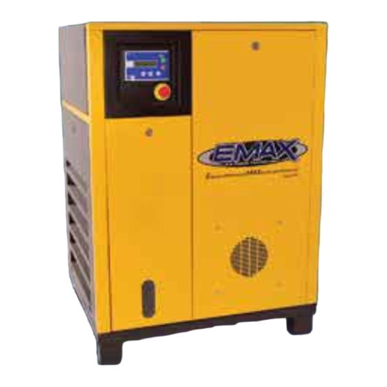
- Page 1 EMAX Rotary Screw Compressors...
-
Page 2: Table Of Contents
Warranty ............42 Variable Speed Drive The variable speed drive is an auxiliary feature available on all EMAX compressors. A variable speed drive or VSD regulates amp draw during start-up and motor speed during operation according to air demand. All EMAX compressors are equipped with a VSD compliant motor ventilated electrical box & adequate space in compressor cabinet for easy installation. -
Page 3: Model Specification Charts
1-1/2 gal (6 L) L•W•H Dimensions 26”x34”x43” 26”x34”x43” 26”x34”x43” 34”x24”x43” 32”x37”x50” 32”x37”x50” (inches) Weight (lbs.) EMAX Rotary Screw Systems: 25 Hp - 60 Hp (VSD Compliant) ERS0250003 ERS0300003 ERS0400003 ERS0500003 ERS0600003 Model No. Three Phase Three Phase Three Phase Three Phase... -
Page 4: Safety Information
Operating Instructions EMAX Rotary Screw Systems: 75 Hp - 200 Hp (VSD Compliant) ERS0750003 ERS1000003 ERS1250003 ERS1500003 ERS1750003 ERS2000003 Model No. Three Phase Three Phase Three Phase Three Phase Three Phase Three Phase Description Dual Voltage Dual Voltage Dual Voltage... -
Page 5: Basic Guidelines
EMAX Rotary Screw Compressors Basic Guidelines CALIFORNIA PROPOSITION 65 This product or its power cord may contain chemicals known to the State WARNING of California to cause cancer and birth defects or other reproductive harm. Wash hands after handling. 1. -
Page 6: Inspection
WARNING pallet before moving. NEVER attempt to move a compressor that is not secure as serious injury or property damage could occur. A forklift may be necessary for unloading the EMAX compressor. and requires a certified forklift operator, using all forklift safety measures. Refer to figure 1 for safe unloading procedures. Forklift Safety Be sure load is secure and well balanced before moving compressor. -
Page 7: Installation
EMAX Rotary Screw Compressors Installation Area Exhaust air from this unit can be used to supplement environment heat. Install unit in separate room then create duct system as shown in figure 3. 1. Install compressor in a clean, well ventilated and well lit area. Make sure air inlet is away from exhaust fumes or other toxic, noxious or corrosive fumes or substances. Installation area must maintain low relative humidity and a temperature range between 35o – 110 o F (2o – 43 o C). This unit must be kept under roof and away from rain, snow, etc. -
Page 8: Installing
Operating Instructions Installing 1. Install piping as shown in Figure 4. Refer to Figure 5 for recommended, closed loop installation. 2. Make sure any tube, pipe or hose connected to the unit can withstand operating temperatures and retain pressure. Never use plastic (PVC) pipe for compressed air. Serious injury or WARNING death could result. Minimum Pipe Size For Compressed Air Lines (Pipe size shown in inches) SCFM 25 ft. 50 ft. 100 ft. -
Page 9: Oil Check
EMAX Rotary Screw Compressors 5. For permanent installations of compressed air systems, determine total length of system and select correct pipe size. Bury underground lines below frost line and avoid areas where condensation could build-up and freeze. Test entire piping system before underground lines are buried, and find and repair all leaks before using compressor. Oil Check This unit is shipped with oil in it and ready to operate. Check for proper oil level before operating the compressor. -
Page 10: Motor Rotation
Operating Instructions Follow all NEC and local codes for electrical wiring. Allow only authorized EMAX service person or Wiring for Variable Speed Drive or typical Wye- certified electrician to install electrical components. Delta Start. See page 1 for advantages of VSD. Put unit on dedicated circuit and make sure no other electrical equipment is wired into it. -
Page 11: System Description
Refer to figure 8 for explanation of buttons. Maintenance Notifications Six automatic maintenance notifications are built into the EMAX compressor system designed to signify when maintenance is due for certain components. The user is notified by a message displayed on the control panel. Refer to the following chart for the components that have automatic maintenance notifications and their factory set lifetimes. - Page 12 Operating Instructions Setting:oC/ oF; BAR/PSI; Language; Time/Date Press the Up arrow for setting temperature scale, gauge pressure, language, time & Main screen starting point. date. Now the current flashing gauge pressure Press the Enter button to see the current setting, BAR (metric) or PSI (Am. Std) flashing temperatures scale, oC (Celcius) or shows in display. Use the Up & Down oF (Fahrenheit). Use the Up & Down arrows arrows to change, if desired, and then press to change, if desired, and then press Enter Enter to set the value.
-
Page 13: Working Pressures
EMAX Rotary Screw Compressors The current language setting now shows in The current date, day of week and time the display. Use the Up & Down arrows to now shows in the display. Starting with the change to the desired language and then flashing date, use the Up & Down Arrows press Enter. to change the setting and then press Enter. Now the next parameter flashes... -
Page 14: Clock Timer Settings
Operating Instructions Enter in the 6 Digit Password 6 6 6 6 6 6, by using the Up Arrow to set the digit to 6 then press Enter to move to the next digit, and press the Up Arrow to set to 6, repeat until last digit is set to 6, then press Enter. Arrow down to 0)WORKING PRESSURES Press both Up & Down Arrows and press Enter. NOTICE again if the wrong password is entered. -
Page 15: Working Timer - Unloading Delay
EMAX Rotary Screw Compressors Working Timer - Unloading Delay To reduce wear & tear of the compressor components, an unloading delay time is set in the controls that shuts-down the compressor after the unloading delay time has counted down. If the compressor is running in slow periods of the day, the compressor could run for long periods in the unloading stage, causing unnecessary component wear and elevated energy costs. With an unload delay time of 10 minutes, for example, the compressor would run for 10 minutes in the unloading stage and then it would shut down and enter a stand-by mode. Then when the low pressure setting is reached, the compressor automatically starts again. To view or set the unload delay time, start Press the two arrow keys at the same time to with the main screen shown below. -
Page 16: Maintenance Notifications
Operating Instructions Arrow down to Wt4 (Unload delay time). Press Enter and the time flashes and can be changed by using the Up & Down Arrows. Press Enter Once satisfied with all settings, press Down again to confirm the setting. (See chart on page Arrow until you are back to the Main Screen. 17 of PLC manual.) Maintenance Notifications Component (PLC) Lifetime (hrs) Following replacement times are important for safe Air Filter... - Page 17 EMAX Rotary Screw Compressors Resetting Maintenance Alarms (Continued) Arrow down to 6)OIL/FILTER-HOURS and Enter in the 6 Digit Password 6 6 6 6 6 6, by press Enter using the Up Arrow to set the digit to 6 then press Enter to move to the next digit, and press the Up Arrow to set to 6, repeat until last digit is set to 6, then press Enter. Press both Up & Down Arrows...
- Page 18 Operating Instructions Resetting Maintenance Alarms (Continued) Using Enter move over to NO and use the Up Arrow to change it to YES then hit Enter and it Press Down Arrow and CHANGE SEP. resets the hours. Separator filter should be set (Separator) FILTER shows in the display. at 4000 hours.
- Page 19 EMAX Rotary Screw Compressors Resetting Maintenance Alarms (Continued) Press Down Arrow and BEARING LUBRICATE Using Enter move over to NO and use the Up shows in the display. Press Enter. Arrow to change it to YES then hit Enter and it resets the hours.
-
Page 20: Mechanical Components
Drive motor is 4 pole with low RPM (1750). This motor is also capable of variable speed drive as a standard feature. The motor is 12 lead, Y delta soft starting for low amp draw. Overload protection is installed for safety. Normal electric current can fluctuate slightly for various reasons but if the current spikes, the overload protection causes the motor(s) to stop. If this happens, the motors must be reset manually. Reasons for tripped overload protection: Operator error: Improper regulation of air exhaust pressure or other parts of the system. Branch circuit not sized correctly Mechanical failures: • Internal motor failure • Improper motor phasing • System setting error • Blocked air/oil separator filter If motor overload protection is caused by any other reason, contact EMAX immediately. -
Page 21: Resetting Overload Protection
EMAX Rotary Screw Compressors Resetting Overload Protection Disconnect, tag & lock out electrical power to unit, or electrical shock WARNING could result. Using lock key, remove electrical panel Locate BLUE reset button on relay from unit attached to K1 contactor. Once motor has cooled, press-in on BLUE Example of relay on larger units. - Page 22 Operating Instructions variable speed drive (Energy saving device) Ready Cabinet This cabinet has allocated space and cooling fan to house variable speed drive components. To convert to variable speed drive, contact EMAX customer service for more information, 1-877-283-7614. Air Suction Filter (Air Intake) A dry type paper filter with filtration of 5 ppm, replace after first 600 hours of operation; then every 4000 hours, depending on environment. Refer to the computer controls of the compressor to monitor operating time and reset maintenance timer when filter is replaced.
- Page 23 EMAX Rotary Screw Compressors Exhaust Probe The probe is temperature sensitive and located at the air outlet of the rotary screw casing. When exhaust temperature exceeds 210°F (98.8°C), the system automatically powers OFF. The temperature of the air exhaust can be read on a display panel located on the PLC. Common reasons for excessive exhaust temperatures: • low oil level • inoperable exhaust fan • improper ventilation causing ambient air temperature to be too hot • clogged oil filter • clogged radiator not allowing air-flow to cool oil It is important to keep the circulating fan and cooler fins clean to prevent the compressor from shutting down. Low air pressure can be used to blow them off or if needed, use waterbased solvent to clean.
- Page 24 Operating Instructions Air/Oil Separator Filter During the process of air compression from pump, air and oil are mixed together to lubricate, seal and cool compressor rotors. This air and oil is transferred to air/ oil separator tank and then the air/oil separator filter removes oil mist from the compressed air. The filter core is made of multiple-layer fine glass fibers. The filter reduces the oil particle size and can lower content to less than 3 PPM. During normal operation, the air/oil separator filter can be used for about 4000 hours or annually, whichever comes first. Refer to the computer controls of the compressor to monitor operating time and remember to reset maintenance timer when filter is...
-
Page 25: Operation
EMAX Rotary Screw Compressors Refrigerated Dryer/Coalescing Filter (optional, not shown) The refrigerated dryer removes moisture content. The coalescing filter removes oil droplets and impurities in the compressed air. The refrigerated dyer/coalescing filter operates best with an automatic drain that removes water condensation collected during the air drying process. -
Page 26: Initial Checks
Operating Instructions To avoid serious injury, keep all persons away from the discharge opening of hoses or tools or other points of compressed air discharge. If the machine is installed in an enclosed area, be sure to vent the relief valve outside of the structure or to an unoccupied area. -
Page 27: Start-Up
Be sure to close valve after draining water. Check “Emergency Stop” function by pressing the button shortly after pressing ON button. Do not operate the machine if there is any abnormal noise or vibration during operation. Call EMAX service for assistance. -
Page 28: Storage
Operating Instructions Storage If the machine is stopped for over three weeks: a) Wrap electrical equipment such as the control panel with plastic or oil paper to avoid condensation. b) Completely drain water in the oil cooler, the back cooler and the oil/air separator tank. Make sure any unsafe conditions are clearly stated or repaired. If the machine is not run for more than two months: Seal all ports to prevent moisture or dust accumulation. b) Wrap safety valve & control panel with oil paper or an equivalent to avoid rust. -
Page 29: Lubricating Oil
CAUTION Lubricating Oil To avoid water condensation during operation, keep oil temperature between 160° - 190° F (70° - 88° C). Failure to do so causes pump damage. Contact EMAX service if temperature drops below 160° F (70° C). Changing Oil Shut down compressor and allow machine to set for 5-10 minutes. Air/Oil Separator tank is a pressurized component. To avoid serious injury, be sure system pressure is relieved before removing fill plug. -
Page 30: Oil Capacities
Operating Instructions 2. Drain oil completely. Be sure to include oil in system piping, cooler and air/oil separator tank. Close drain valve. 3. Remember to remove and change oil filter, taking care to avoid hot oil during replacement. Open oil fill port and add new oil. Oil Capacities: CAUTION 7.5– 10 HP – 5 liters (1 gal/2.5 pints) 15 – 20 HP – 6 liters (1 gal/4.6 pints) DO NOT OVERFILL. Residual oil may still be in the 25 –... -
Page 31: System Pressure
EMAX Rotary Screw Compressors System Pressure System pressure is factory set but can be regulated depending on operating conditions. Refer to computer control specifications for setting adjustments or PLC operating manual. Safety Valve TO AVOID SERIOUS INJURY OR DEATH, NEVER ATTEMPT TO REGULATE OR TAMPER WITH SAFETY VALVE. -
Page 32: Maintenance Schedule
Operating Instructions Maintenance Schedule Daily Check oil level Check safety valve Check coolant level Drain condensed water Weekly Clean air filter General unit cleaning Check belt tension 500 hrs. Change lubricating oil (after first 500 hrs.) Grease electric motor bearings ... -
Page 33: Troubleshooting
EMAX Rotary Screw Compressors Troubleshooting Chart Problem Possible Causes Resolutions Compressor will not start Power supply problem Check complete circuit for proper (Electric failure light is on) voltage, ensure all electrical connections are secure; once power is restored, press Enter button on controls. Blown circuit fuse and/or internal Replace fuse(s) as needed... - Page 34 Operating Instructions Problem Possible Causes Resolutions Compressor shuts down under Loss of Control Voltage Reset-Press Enter button on controls. If compression mode/while load- trouble persists, check line pressure ing (Continued) does not exceed maximum operating pressure of the compressor (specified on nameplate) Low incoming Voltage 3. Wire size for power supply too small.
- Page 35 EMAX Rotary Screw Compressors Problem Possible Causes Resolutions Line pressure exceeds upper 2. High pressure shut-down preset Reset to proper setting. Refer to PLC preset safety limit (Continued) manual. is incorrectly programmed Reset additional compressor pressure Additional compressor piped into settings to 145 psi or lower...
- Page 36 Contact EMAX Compressor dryer in air system Excessive noise level V-belts slipping Adjust belt tension or replace belts Compressor defective (Bearing Replace bearing; Contact EMAX failure or rotor contact) Compressor Enclosure panels not in place Install enclosure panels Loose component mounting Inspect &...
- Page 37 Align sheaves Excessive belt wear Replace belts Using non-OEM belt Use ONLY OEM parts Shaft seal leak Defective shaft seal Replace or contact EMAX Compressor During start-up, PLC shows Blown fuse/breaker for control Replace fuse or reset breaker normal running functions, but voltage compressor not running Faulty E-Stop button –...
-
Page 38: Wiring Diagrams
Operating Instructions... - Page 39 EMAX Rotary Screw Compressors...
- Page 40 Operating Instructions...
- Page 41 EMAX Rotary Screw Compressors...
-
Page 42: Warranty
Purchaser’s discretion and obligation (at Purchaser’s expense) to have a redundant DRYER UNIT. Warranty repairs shall not include freight costs. Purchaser is responsible for returning unit to EMAX COMPRESSOR. Each DRYER UNIT must have a coalescing filter attached to the intake of the dryer to remove any oil or dirt before air enters the dryer. Failure to install coalescing filter will void the warranty.
Need help?
Do you have a question about the ERS0070001 and is the answer not in the manual?
Questions and answers