
Related Manuals for Vicon Fanex 903 CD


Summary of Contents for Vicon Fanex 903 CD
- Page 1 Fanex 903 CD Assembly instructions Original assembly instructions Edition 01.2010 Date of print 10.2010 Language Machine number VF69240001 – Model 6924 Document number VF16647316.EN...
- Page 2 Kverneland Group Kerteminde AS Taarupstrandvej 25 DK-5300 Kerteminde Denmark Tel: +45 65 19 19 00 Copyright by Kverneland Group Gottmadingen N. V., Germany. Reproduction, transfer to other media, translation or the use of extracts or parts of this manual without the explicit permission of Kverneland, is not permitted. All rights reserved. The contents of these assembly instructions are subject to change without notice.
-
Page 3: Table Of Contents
Table of contents Table of contents Preliminary information ......Target group for these assembly instructions Meaning of the symbols Safety ............For your safety Screwed connections Direction information Overview ............ Components Crate packaging Small parts Set of lights Crate packaging ........Preparations for assembly Assemble the basic machine View 1... -
Page 4: Preliminary Information
Preliminary information Target group for These instructions are intended for authorised dealers, workshops Preliminary information and agents qualified in the field of agricultural mechanical engineer- these assembly ing. instructions For your safety You must familiarise yourself with the contents of these assembly in- structions before assembly or operating the machine. -
Page 5: Meaning Of The Symbols
Preliminary information Meaning of the In these assembly instructions, the following symbols and terms have been used: symbols • A bullet point accompanies each item in a list. A triangle indicates operating functions which must be performed. The checklist symbol indicates important points which you must check. -
Page 6: Safety
Safety For your safety Please carefully read and observe the safety information in this chap- Safety ter prior to assembly. All persons involved in assembling or setting up this machine must read and pay close attention to the assembly in- structions that follow. - Page 7 Safety General safety and Requirements • accident prevention Responsibilities for the various activities on the machine must be clearly defined and maintained. There must not be any confusion regulations regarding responsibilities, otherwise the safety of the assembly personnel is put at risk. •...
-
Page 8: Screwed Connections
Safety Screwed Use original parts Machine components have special properties that are essential for the connections stability and correct operation of the machine. Only spare parts and accessories supplied by the manufacturer have been tested and ap- proved. Other products may adversely affect the correct operation of the machine and safety. -
Page 9: Direction Information
Safety Direction Direction information (right, left, front, rear) is given in relation to the direction of travel. information Rotary direction is defined as follows: Description Rotary direction right Clockwise Rotary direction left Anti-clockwise Rotation about the vertical axis Viewed from above Rotation about the horizontal At right-angles to the direction of travel viewed from left to right axis... - Page 10 Safety Special tightening Special tightening torques are used for certain screwed connections. These are mentioned in the manual. Please also note the special tight- torques ening torques for the following screwed connections: • 130 Nm tine arms, inside. 130 Nm •...
-
Page 11: Overview
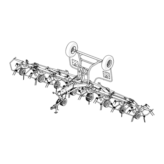
Overview Components Overview 1st side device Centre device 2nd side device Transport wheel Outer device Transport chassis Warning signs with lighting unit Deflector bar Deflector frame Rotor Bottom hitching Sustainer Contact roller Wheel Main frame Deflector bridge... -
Page 12: Crate Packaging
Overview Crate packaging Wheel Transport wheel Shafting Bottom hitching Wheel Small parts Transport chassis Raking wheel arms... -
Page 13: Small Parts
Overview Small parts Assembly material Tine gauge for deflector bridge Assembly parts for wheel axles Caps for transport chassis Spring for contact roller Assembly material for deflector bar Traction rope for angled position system Screws and nuts for raking wheel arm... -
Page 14: Set Of Lights
Overview Set of lights Rear light Warning plate Assembly instructions Cable tie Warning board retainer Fixing material... -
Page 15: Crate Packaging
Crate packaging Preparations for The machine is supplied partly assembled. Assembly may only be car- Crate packaging ried out by skilled, qualified personnel. Preassembled components assembly must not be removed. Requirements • Suitable flat surface approx. 10 x 10 m as assembly space. •... - Page 16 Crate packaging Open crate Place the wooden crate on level ground (with the pallet floor at the bottom) and open it without damaging the parts inside. Inspect the contents of the crate for damage caused during transport. Take out loose parts (wheels, axles, boxes etc.). Check that the delivery has been supplied in full.
-
Page 17: Assemble The Basic Machine
Crate packaging Assemble the basic machine The basic machine is the combination of the side and outer devices pre-assembled at the factory with the centre device. 2. Straighten To raise and straighten the basic machine, lifting gear with lifting ac- cessories for at least 1,500 kg is required. -
Page 18: View 1
Crate packaging View 1 Main frame Side device Stand Hydraulic hoses Centre device Shafting... -
Page 19: Fitting The Main Frame
Crate packaging Fitting the main When fitting the main frame, please observe the safety information for the lifting gear. frame Angle the unhitched basic machine by approximately 10° in the direction of travel. → See »View 1«, page 18. Bolts Bring the main frame closer to the unhitched basic machine using lifting gear. - Page 20 Crate packaging Fitting the The shafting is pre-assembled. shafting Fill the bushing on the shafting with anti-friction grease. Push the shafting onto the PTO stub shaft on the centre device. Shafting...
-
Page 21: View 2
Crate packaging View 2 Main frame Transport chassis Contact roller Stand... -
Page 22: Transport Chassis
Crate packaging Transport chassis Fitting the transport Note the safety information for lifting gear when fitting the transport chassis to the centre device. chassis Bring the transport chassis closer to the unhitched basic machine using lifting gear. Quantity Part Transport chassis Centre device Transport chassis Align the transport chassis to the lugs on the centre device. - Page 23 Crate packaging Fitting the lift cylinder Raise the transport chassis using lifting gear and secure. Mount the lift cylinder for the transport chassis on the centre Lift cylinder for transport chassis device. Insert the pins through the bores on the lift cylinder and centre device.
- Page 24 Crate packaging Fitting the contact roller Fit the contact roller. Fit the contact roller in the support on the main frame and secure. Quantity Part Contact roller Make sure when installing the contact roller that the spring is correctly positioned. Couple the machine to the tractor and secure.
-
Page 25: Coupling The Hitch
Crate packaging Coupling the hitch To couple the machine with the tractor, proceed as follows: Secure the machine against rolling away (use wheel chocks). Move the tractor into position. Secure the tractor against rolling away, shut off the engine and remove the ignition key. -
Page 26: Connecting The Hydraulic System
Crate packaging Connecting the The hydraulic system is pre-fitted. hydraulic system Close the ball valve. Set the tractor hydraulics to “free float”. open Connect the implement's hydraulic coupling to two connections of the double-acting control device. After fitting, extend and retract the hydraulic cylinders from the end position at least 10 times in order to bleed the cylinders. -
Page 27: View 3
Crate packaging View 3 Running wheel 16 x 6.5 Running wheel 18.5 x 8.5... -
Page 28: Fitting The Running Wheels
Crate packaging Fitting the running The machine is coupled to the tractor and the hydraulics are correctly connected. Observe the instructions and warnings in the tractor man- wheels ufacturer's operating manual. Fitting the transport Fit the transport chassis wheels as follows: chassis wheels Lower the transport chassis hydraulically. -
Page 29: Fitting The Wheel Axles
Crate packaging Fitting the wheel The machine is fitted with 8 running wheel axles. axles During fitting, ensure the correct placement and alignment of the wheel axles (cf. illustration). Overview of wheel axles Variant 1: trailing axle Variant 2: special running wheel axle Running wheel axle Variant 1: trailing Variant 2: special... - Page 30 Crate packaging Fitting wheels A + B Fit axles with wheels to the centre device and to the inner side device: Switch on the tractor. Fold out the transport chassis completely using the tractor's hydraulic control device. Secure the tractor against rolling away, shut off the engine and remove the ignition key.
- Page 31 Crate packaging Fitting wheels C - E Fit axles with wheels to the outer side device and to the outer device: Switch on the tractor. Fold out the machine using the tractor's hydraulic control device until the fitted wheels on the inner side device are standing on the ground.
-
Page 32: Final Assembly
Final assembly Preparing the Final assembly wheel axles Lynch pin High-strength pin Note the marking on the pins The wheel axles for the centre device (18.5 x 8.5 wheel) are fas- tened using special high-strength pins. These pins have a special marking. - Page 33 Final assembly Wheel axles for the centre device (wheel A) Insert the wheel axles into the locking piece and secure with a washer and nut. Lynch pin High-strength pin Insert the high-strength pin (with marking) into the middle hole on the locking piece and secure with a lynch pin Quantity Part...
- Page 34 Final assembly Variant 1: trailing axle for wheel E Insert the wheel axles into the locking piece and secure with a washer and cotter pin. Lynch pin Insert the pins into the same hole as the centre device wheel axles and secure with the lynch pin Quantity Part...
-
Page 35: Fitting The Tine Arms
Final assembly Fitting the Depending on the direction of rotation of the rotors, tine arms are at- tached on the left or right. tine arms → Please note the diagram »Adjusting the tine arms« on page 36. Never work under the rotors Do not carry out work on raised rotors unless they have been se- cured. - Page 36 Final assembly Adjusting the tine arms Adjusting the tine arms On rotors 1, 3, 5 and 7 attach On rotors 2, 4, 6 and 8 attach 2 3 4 all tine arms on the left. all tine arms on the right. When fitting the tine arms, pay attention to the rotational direction of the rotor and the tine position.
-
Page 37: Assembling The Protective Equipment
Final assembly Assembling the protective equipment Overview Illuminated warning sign Deflector bar Transport locking device Deflector frame Deflector bridge... - Page 38 Final assembly Preparation In order to fit the deflector bar and illuminated warning signs, the ma- chine must be moved to the work position. No persons within the slewing range No persons may remain in the slewing range of the side devices or transport chassis during the folding procedure.
- Page 39 Final assembly Fitting the deflector bar Fit the deflector bars on the left and right using M 10 x 30 bolts, washers and nuts. Quantity Part M 10 x 30 bolt M 10 washer M 10 nuts Fitting the deflector bridge Fit the deflector bridge to the front right and left deflector bars using clamps, M 8 x 45 bolts and nuts.
-
Page 40: Fitting The Pto Shaft
Final assembly Fitting the PTO The length of the PTO shaft has been selected by the factory so that it fits almost all types of tractor. shaft In exceptional cases, however, a correction of the PTO shaft length is required on individual tractors. Free wheel Couple wide angle to Tractor... -
Page 41: Coupling The Pto Shaft
Final assembly Coupling the PTO When coupling the PTO shaft, make sure it is in the correct position. shaft Check whether the PTO shaft must be shortened before coupling. Shorten the PTO shaft if necessary. → »Adapting the PTO shaft«, page 42 Check that the tractor's PTO stub shaft is clean and lubricated. -
Page 42: Adapting The Pto Shaft
Final assembly Adapting the PTO The length of the PTO shaft must fit the tractor. The PTO shaft length must be checked for every tractor before first use: shaft Safety An original operating manual from the manufacturer is included with every PTO shaft. -
Page 43: Circuit Diagrams
Circuit diagrams Hydraulics Circuit diagrams Overview View A closed open Tractor Lift cylinder View B Lift cylinder Border tedding (left and right) Tractor... -
Page 44: Hydraulics Circuit Diagram
Circuit diagrams Hydraulics circuit diagram Hydraulic cylinder for Hydraulic cylinder for transport chassis angled position system Hydraulic cylinder for the right-hand Hydraulic cylinder for the left- side device hand side device Restrictors Restrictors dia. 1.5 (dia. 1.0)* dia. 2.5 dia. 2.5 dia. -
Page 45: Final Operations
Final operations Checking the Upon completion of assembly check the following: Final operations assembled Tightening torque of all screws. machine Hydraulic connections. Laying of hydraulic hoses, ropes and cables. Cable connections. PTO drive shaft connections engaged? Lighting. Tyre pressures according to table: Tyre size Tyre pressure... -
Page 46: Trial Run
Final operations Trial run No persons within the slewing range There is an extreme risk of injury within the slewing range from slewing or folding machine parts. Referring to the operating manual, adjust the machine and carry out a trial run. All hydraulic cylinders are connected already, the system is filled with oil.
Need help?
Do you have a question about the Fanex 903 CD and is the answer not in the manual?
Questions and answers